
Operating Instructions
Page 4
... audio components ........19 4b: Connecting the video components .......24 5: Connecting the antennas (aerials 35 6: Preparing the receiver and the remote ....36 7: Operating the receiver using the GUI (Graphical User Interface 39 8: Setting the speakers 42 9: Calibrating the appropriate speaker settings automatically (Auto...menu 57 Settings for the system (System settings menu 58 Enjoying Surround Sound Enjoying a pre-programmed sound field ... 59 Resetting sound fields to the initial settings 65 Enjoying the surround effect at low volume levels (NIGHT MODE 66 Advanced Speakers Setting ...
... audio components ........19 4b: Connecting the video components .......24 5: Connecting the antennas (aerials 35 6: Preparing the receiver and the remote ....36 7: Operating the receiver using the GUI (Graphical User Interface 39 8: Setting the speakers 42 9: Calibrating the appropriate speaker settings automatically (Auto...menu 57 Settings for the system (System settings menu 58 Enjoying Surround Sound Enjoying a pre-programmed sound field ... 59 Resetting sound fields to the initial settings 65 Enjoying the surround effect at low volume levels (NIGHT MODE 66 Advanced Speakers Setting ...

Operating Instructions
Page 36
...lead) firmly. Notes • Before connecting the AC power cord (mains lead), make sure that metallic wires of the speaker cords are reset to their factory defaults. AC INLET terminal To the wall outlet AC power cord (mains lead) (supplied) Performing initial setup operations Before using ...the receiver for the first time, initialize the receiver by performing the following procedure. The cord is not malfunction. 36US This is supposed to be used to return settings you...
...lead) firmly. Notes • Before connecting the AC power cord (mains lead), make sure that metallic wires of the speaker cords are reset to their factory defaults. AC INLET terminal To the wall outlet AC power cord (mains lead) (supplied) Performing initial setup operations Before using ...the receiver for the first time, initialize the receiver by performing the following procedure. The cord is not malfunction. 36US This is supposed to be used to return settings you...

Operating Instructions
Page 37
...batteries with old ones. • Do not mix manganese batteries and other Sony component respond to the same remote command, switch the command mode of the receiver 2CH/A.DIRECT Turn on the display. MODE AV1" appears on the receiver while pressing 2CH/A.DIRECT. RM-AAP025 RM-AAU039 Notes • Do .... • Do not use the remote to "AV1", "C. About the command mode The receiver and the remote use the remote for an extended period of the initial setting (AV SYSTEM 2), it is not necessary to reset them. continued 37US Doing so may be cleared. If the command modes of the...
...batteries with old ones. • Do not mix manganese batteries and other Sony component respond to the same remote command, switch the command mode of the receiver 2CH/A.DIRECT Turn on the display. MODE AV1" appears on the receiver while pressing 2CH/A.DIRECT. RM-AAP025 RM-AAU039 Notes • Do .... • Do not use the remote to "AV1", "C. About the command mode The receiver and the remote use the remote for an extended period of the initial setting (AV SYSTEM 2), it is not necessary to reset them. continued 37US Doing so may be cleared. If the command modes of the...

Operating Instructions
Page 65
... "LARGE" in the Speaker settings menu. Resetting sound fields to the initial settings Be sure to use DCS technology. Dolby TrueHD signals with DCSmarks use the buttons on the display and all the speakers are being received. - The multi channel PCM signals are received via a HDMI IN jack. • ...When one of more than 48 kHz are set to turn off the receiver. 2 While holding down MUSIC, press POWER. the front and surround...
... "LARGE" in the Speaker settings menu. Resetting sound fields to the initial settings Be sure to use DCS technology. Dolby TrueHD signals with DCSmarks use the buttons on the display and all the speakers are being received. - The multi channel PCM signals are received via a HDMI IN jack. • ...When one of more than 48 kHz are set to turn off the receiver. 2 While holding down MUSIC, press POWER. the front and surround...

Operating Instructions
Page 84
..., then press V/v to select "Parental Lock", then press or b. 4 Press V/v repeatedly to using "Direct Tuning" (page 81). "The channel has been unlocked." "The channel has been locked." appears. 5 Reenter the new lock code with the numeric buttons. To cancel the Parental Lock 1 Press V/v repeatedly to select... Press SHIFT, then press the numeric buttons to the default (0000), but the Parental Lock settings are skipped. • When the receiver is reset to the factory settings, the lock code returns to enter your 4-digit lock code. Enter your 4-digit lock code." If you have...
..., then press V/v to select "Parental Lock", then press or b. 4 Press V/v repeatedly to using "Direct Tuning" (page 81). "The channel has been unlocked." "The channel has been locked." appears. 5 Reenter the new lock code with the numeric buttons. To cancel the Parental Lock 1 Press V/v repeatedly to select... Press SHIFT, then press the numeric buttons to the default (0000), but the Parental Lock settings are skipped. • When the receiver is reset to the factory settings, the lock code returns to enter your 4-digit lock code. Enter your 4-digit lock code." If you have...

Operating Instructions
Page 135
...tuning scale to either 9 kHz or 10 kHz. Specifications AUDIO POWER SPECIFICATIONS POWER OUTPUT AND TOTAL HARMONIC DISTORTION: With 8 ohm loads, both channels driven, from 250 milliwatts to rated output. FM tuner section Tuning range 87.5 - 108.0 MHz Antenna (aerial) FM wire antenna (aerial...Loop antenna (aerial) Intermediate frequency 450 kHz 5)You can change the tuning scale. To reset the scale to 10 kHz (or 9 kHz), repeat the procedure. After tuning in any AM station, turn off the receiver. Frequency response PHONO RIAA equalization curve ± 0.5 dB Analog 10 Hz - 100 kHz...
...tuning scale to either 9 kHz or 10 kHz. Specifications AUDIO POWER SPECIFICATIONS POWER OUTPUT AND TOTAL HARMONIC DISTORTION: With 8 ohm loads, both channels driven, from 250 milliwatts to rated output. FM tuner section Tuning range 87.5 - 108.0 MHz Antenna (aerial) FM wire antenna (aerial...Loop antenna (aerial) Intermediate frequency 450 kHz 5)You can change the tuning scale. To reset the scale to 10 kHz (or 9 kHz), repeat the procedure. After tuning in any AM station, turn off the receiver. Frequency response PHONO RIAA equalization curve ± 0.5 dB Analog 10 Hz - 100 kHz...
Operating Instructions
Page 138
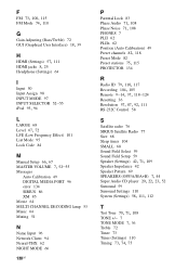
...52-55 Messages Auto Calibration 49 DIGITAL MEDIA PORT 96 error 134 SIRIUS 86 XM 85 Movie 64 MULTI CHANNEL DECODING lamp 53 Music 64 Muting 51 N Name Input 96 Network Client 94 Neural-THX 62 NIGHT MODE ... Audio 71, 108 Phase Noise 71, 108 PHONES 7 PLII 62 PLIIx 62 Position (Auto Calibration) 49 Preset channels 82, 118 Preset Mode 82 Preset stations 75, 115 PROTECTOR 134 R Radio ID 79, 110, 117 Recording 104,... 105 Remote 9-14, 37, 118-124 Resetting 36 Resolution 57, 87, 92, 111 RS-232C Control 58 S Satellite radio 76 SIRIUS Satellite Radio 77 ...
...52-55 Messages Auto Calibration 49 DIGITAL MEDIA PORT 96 error 134 SIRIUS 86 XM 85 Movie 64 MULTI CHANNEL DECODING lamp 53 Music 64 Muting 51 N Name Input 96 Network Client 94 Neural-THX 62 NIGHT MODE ... Audio 71, 108 Phase Noise 71, 108 PHONES 7 PLII 62 PLIIx 62 Position (Auto Calibration) 49 Preset channels 82, 118 Preset Mode 82 Preset stations 75, 115 PROTECTOR 134 R Radio ID 79, 110, 117 Recording 104,... 105 Remote 9-14, 37, 118-124 Resetting 36 Resolution 57, 87, 92, 111 RS-232C Control 58 S Satellite radio 76 SIRIUS Satellite Radio 77 ...

Service Manual
Page 2
... any AM station, turn off the receiver. All preset stations will be erased when you change the tuning scale. To reset the scale to 10 kHz (or..., THD 0.7%) 110 W + 110 W Surround Mode Output Power2) (8 ohms, 1 kHz, THD 10%) 150 W per channel 1) Measured under the following conditions: Area code Power requirements U, CA 120 V AC, 60 Hz 2) Reference power output for...(during standby mode) 0.7 W (when "Control for front, center, surround and surround back speakers. STR-DA2400ES/DG920 Amplifier section (DG920) Models of area code U, CA With 10-kHz tuning scale:...
... any AM station, turn off the receiver. All preset stations will be erased when you change the tuning scale. To reset the scale to 10 kHz (or..., THD 0.7%) 110 W + 110 W Surround Mode Output Power2) (8 ohms, 1 kHz, THD 10%) 150 W per channel 1) Measured under the following conditions: Area code Power requirements U, CA 120 V AC, 60 Hz 2) Reference power output for...(during standby mode) 0.7 W (when "Control for front, center, surround and surround back speakers. STR-DA2400ES/DG920 Amplifier section (DG920) Models of area code U, CA With 10-kHz tuning scale:...
Service Manual
Page 20
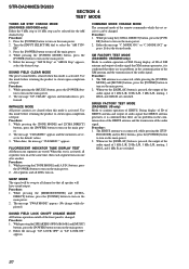
... upon completion of the front panel is changed . When this set receives can be selected for the AM channel step. Procedure: 1. COMMAND MODE CHANGE MODE The command mode of ...Step" or "AM10k Step" appears, select the desired step. INITIALIZE MODE All preset contents are reset to the default values. 3. Use this mode before returning the product to clients upon completion ...and 1 kHz R are tested. STR-DA2400ES/DG920 SECTION 4 TEST MODE TUNER AM STEP CHANGE MODE (DA2400ES: US/DG920 only) Either the 9 kHz step or 10 kHz step can be swap to all channel so that all speaker will be ...
... upon completion of the front panel is changed . When this set receives can be selected for the AM channel step. Procedure: 1. COMMAND MODE CHANGE MODE The command mode of ...Step" or "AM10k Step" appears, select the desired step. INITIALIZE MODE All preset contents are reset to the default values. 3. Use this mode before returning the product to clients upon completion ...and 1 kHz R are tested. STR-DA2400ES/DG920 SECTION 4 TEST MODE TUNER AM STEP CHANGE MODE (DA2400ES: US/DG920 only) Either the 9 kHz step or 10 kHz step can be swap to all channel so that all speaker will be ...

Service Manual
Page 22
... order, the message "SPECIALIZE" appears. 2. Press the [POWER] button to turn on the main power, then while pressing the [TONE MODE] button, press the [A.F.D.], [2CH/A. STR-DA2400ES/DG920 SPECIAL MENU MODE Procedure: 1. Some items can change the content.
... order, the message "SPECIALIZE" appears. 2. Press the [POWER] button to turn on the main power, then while pressing the [TONE MODE] button, press the [A.F.D.], [2CH/A. STR-DA2400ES/DG920 SPECIAL MENU MODE Procedure: 1. Some items can change the content.
Service Manual
Page 24
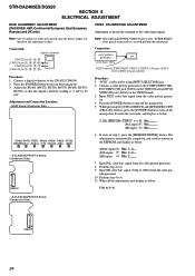
... the main power. The adjustment is automatically completed, and result is selected by using [INPUT SELECTOR] jog. 2. STR-DA2400ES/DG920 SECTION 5 ELECTRICAL ADJUSTMENT BIAS ALIGNMENT ADJUSTMENT (DA2400ES: AEP, Continental European, East European, Russian and UK only) VIDEO CALIBRATION ADJUSTMENT Adjustment to decide the standard of ...8. Input HD color bars signal (720p or 1080i) from the color pat- Note: After replacing DIGITAL VIDEO board, or after "SUPER RESET" of the special menu mode is executed, perform this adjustment is 5 mV to turn off the main power 5. Adjust the RV400 (...
... the main power. The adjustment is automatically completed, and result is selected by using [INPUT SELECTOR] jog. 2. STR-DA2400ES/DG920 SECTION 5 ELECTRICAL ADJUSTMENT BIAS ALIGNMENT ADJUSTMENT (DA2400ES: AEP, Continental European, East European, Russian and UK only) VIDEO CALIBRATION ADJUSTMENT Adjustment to decide the standard of ...8. Input HD color bars signal (720p or 1080i) from the color pat- Note: After replacing DIGITAL VIDEO board, or after "SUPER RESET" of the special menu mode is executed, perform this adjustment is 5 mV to turn off the main power 5. Adjust the RV400 (...

Service Manual
Page 33
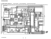
...LED DRIVE Q709, 710 (GRN) LED DRIVE Q701, 711 (RED) LED DRIVE Q702 D702 Digital Cinema Sound D703 MULTI CHANNEL DECODING LED DRIVE Q704 DIMMER CONTROL Q703 SIGNAL PATH : VIDEO STR-DA2400ES/DG920 33 33 PD0 - DQ15 A0 - FSDATA31 OCMDATA0 - OCMADDR21 ROM_CS_N AD24 OCN_RE_N AC25 OCN_WE_N AC26 F_D [0] - F_A... 125 VIDEO_DAC_SDA 142 FLI_BUSY 141 FLI_RX 140 FLI_TX 136 FLI_RESET 33 HSYNC 32 VSYNC 19 CLKIN 13 14 20 SDA/SCKI SCL/MOSI RESET REMOTE CONTROL RECEIVER IC701 SW1 (1/2) POWER STBY +3.3V S711, 712 113 112 124 S701 - 705 S113 - 115, S708 S715 INPUT SELECTOR ROTARY...
...LED DRIVE Q709, 710 (GRN) LED DRIVE Q701, 711 (RED) LED DRIVE Q702 D702 Digital Cinema Sound D703 MULTI CHANNEL DECODING LED DRIVE Q704 DIMMER CONTROL Q703 SIGNAL PATH : VIDEO STR-DA2400ES/DG920 33 33 PD0 - DQ15 A0 - FSDATA31 OCMDATA0 - OCMADDR21 ROM_CS_N AD24 OCN_RE_N AC25 OCN_WE_N AC26 F_D [0] - F_A... 125 VIDEO_DAC_SDA 142 FLI_BUSY 141 FLI_RX 140 FLI_TX 136 FLI_RESET 33 HSYNC 32 VSYNC 19 CLKIN 13 14 20 SDA/SCKI SCL/MOSI RESET REMOTE CONTROL RECEIVER IC701 SW1 (1/2) POWER STBY +3.3V S711, 712 113 112 124 S701 - 705 S113 - 115, S708 S715 INPUT SELECTOR ROTARY...
Service Manual
Page 58
... R8113 100 JL8080 C JL8079 JL8076 C8016 47 4V (DA2400ES:US) C8017 47 4V Q8001,8002 RESET SWITCH Q8002 RT1P141C-TP-1 D JL8082 C8012 820P C8011 ...21 VSS 1.2 22 COMTXM 1.2 23 COMTXP 24 VSS IC8003 XM RECEIVER IC8003 F2602E-01-TR 3.3 SAIIEN 48 0 SAIIDATA 47 3.3 VDD...DA2400ES:AEP,ECE,UK) CN8004 9P (DA2400ES:US/DG920) JL8075 1 JL8074 JL8073 2 3 JL8072 4 JL8071 5 JL8070 6 JL8069 7 JL8068 8 JL8067 9 JL8066 10 JL8065 11 (DA2400ES:AEP,ECE,UK) TUN_L 9V TUN_R GND TUN_TUNED TUN_CE TUN_DAT TUN_CLK TUN_DO RDS_CLK RDS_DATA TUNER (FM/AM) ANTENNA FM 75 Ω COAXIAL AM STR-DA2400ES...
... R8113 100 JL8080 C JL8079 JL8076 C8016 47 4V (DA2400ES:US) C8017 47 4V Q8001,8002 RESET SWITCH Q8002 RT1P141C-TP-1 D JL8082 C8012 820P C8011 ...21 VSS 1.2 22 COMTXM 1.2 23 COMTXP 24 VSS IC8003 XM RECEIVER IC8003 F2602E-01-TR 3.3 SAIIEN 48 0 SAIIDATA 47 3.3 VDD...DA2400ES:AEP,ECE,UK) CN8004 9P (DA2400ES:US/DG920) JL8075 1 JL8074 JL8073 2 3 JL8072 4 JL8071 5 JL8070 6 JL8069 7 JL8068 8 JL8067 9 JL8066 10 JL8065 11 (DA2400ES:AEP,ECE,UK) TUN_L 9V TUN_R GND TUN_TUNED TUN_CE TUN_DAT TUN_CLK TUN_DO RDS_CLK RDS_DATA TUNER (FM/AM) ANTENNA FM 75 Ω COAXIAL AM STR-DA2400ES...

Service Manual
Page 65
...STR-DA2400ES/DG920 6-39. S702 MOVIE S701 MUSIC STR-DA2400ES...CN717 9P JL753 1 JL804 2 3 4 JL803 5 JL802 6 7 8 9 GND STB +3.3V RESET NC SO SI NC MD2 NC (FOR SERVICE) JL738 JL739 DISPLAY Board - • See Page...100 R777 4.7k JL813 JL812 JL811 JL810 E F (Page 67) AV GND CNP718 6P JL768 1 LED BOARD CN719 NC 2 LED_GREEN 3 ... CL706 12 56 J D702 Digital Cinema Sound D703 MULTI CHANNEL DECORDING 5 5 R735 1k R772 2.2k 0 Q711 ISA1235AC1TP...3.3 VCC D702 SELS5B23C-TP15 D703 SELT5E23C-S TP15 IC701 REMOTE CONTROL RECEIVER IC701 NJL24H400A R719 330 R722 10k C709 0.1 R721 220 R720 ...
...STR-DA2400ES/DG920 6-39. S702 MOVIE S701 MUSIC STR-DA2400ES...CN717 9P JL753 1 JL804 2 3 4 JL803 5 JL802 6 7 8 9 GND STB +3.3V RESET NC SO SI NC MD2 NC (FOR SERVICE) JL738 JL739 DISPLAY Board - • See Page...100 R777 4.7k JL813 JL812 JL811 JL810 E F (Page 67) AV GND CNP718 6P JL768 1 LED BOARD CN719 NC 2 LED_GREEN 3 ... CL706 12 56 J D702 Digital Cinema Sound D703 MULTI CHANNEL DECORDING 5 5 R735 1k R772 2.2k 0 Q711 ISA1235AC1TP...3.3 VCC D702 SELS5B23C-TP15 D703 SELT5E23C-S TP15 IC701 REMOTE CONTROL RECEIVER IC701 NJL24H400A R719 330 R722 10k C709 0.1 R721 220 R720 ...
Service Manual
Page 79
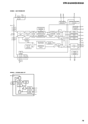
STR-DA2400ES/DG920 IC3800 ADV7392BCPZ HSYNC VSYNC SFL/MISO GND_IO P3 P2 P1 DGND VDD P0 40 39 38 37 36 35 34 33 32 VDD_IO 1 P4 2 ... RSET 29 COMP 28 DAC 1 27 DAC 2 26 DAC 3 25 VAA 24 AGND 23 PVDD 22 EXT_LF 21 PGND POWER MANAGEMENT CONTROL 19 20 CLKIN RESET P11 ALSB/SPI_SS SDA/SCLK SCL/MOSI P12 P13 P14 P15 IC3810 CY2302-SXC-1T FBIN 1 /Q IN 2 GND 3 FS0 4 PHASE DETECTOR LOOP FILTER VCO CHARGE...
STR-DA2400ES/DG920 IC3800 ADV7392BCPZ HSYNC VSYNC SFL/MISO GND_IO P3 P2 P1 DGND VDD P0 40 39 38 37 36 35 34 33 32 VDD_IO 1 P4 2 ... RSET 29 COMP 28 DAC 1 27 DAC 2 26 DAC 3 25 VAA 24 AGND 23 PVDD 22 EXT_LF 21 PGND POWER MANAGEMENT CONTROL 19 20 CLKIN RESET P11 ALSB/SPI_SS SDA/SCLK SCL/MOSI P12 P13 P14 P15 IC3810 CY2302-SXC-1T FBIN 1 /Q IN 2 GND 3 FS0 4 PHASE DETECTOR LOOP FILTER VCO CHARGE...

Service Manual
Page 80
IC403 NJU7311AM (TE2) 30 29 28 27 26 25 24 23 22 21 20 19 18 17 16 VDD R1 R2 R_COM1 R3 R4 R_COM2 R5 R6 R_COM4 R7 R_COM3 NC DATA CK LEVEL SHIFTER LATCH CIRCUIT LATCH CIRCUIT LEVEL SHIFTER CONTROL CIRCUIT 12 3 4 5 6 7 8 9 10 11 12 13 14 15 IC4100 SI-8001FFE ON/OFF SOFT START PREG OVERCURRENT PROTECTION OSCILLATOR RESET LATCH & DRIVER COMPARATOR - + THERMAL PROTECTION - + ERROR AMP REFERENCE VOLTAGE 1 2 345 VEE IN L1 L2 L_COM1 L3 L4 L_COM2 SW L5 GND ADJ L6 SS L_COM3 L7 L_COM4 NC ST GND 80 MAIN Board - STR-DA2400ES/DG920 -
IC403 NJU7311AM (TE2) 30 29 28 27 26 25 24 23 22 21 20 19 18 17 16 VDD R1 R2 R_COM1 R3 R4 R_COM2 R5 R6 R_COM4 R7 R_COM3 NC DATA CK LEVEL SHIFTER LATCH CIRCUIT LATCH CIRCUIT LEVEL SHIFTER CONTROL CIRCUIT 12 3 4 5 6 7 8 9 10 11 12 13 14 15 IC4100 SI-8001FFE ON/OFF SOFT START PREG OVERCURRENT PROTECTION OSCILLATOR RESET LATCH & DRIVER COMPARATOR - + THERMAL PROTECTION - + ERROR AMP REFERENCE VOLTAGE 1 2 345 VEE IN L1 L2 L_COM1 L3 L4 L_COM2 SW L5 GND ADJ L6 SS L_COM3 L7 L_COM4 NC ST GND 80 MAIN Board - STR-DA2400ES/DG920 -

Service Manual
Page 83
... TK11150CSCL-G 5 4 OVER HEAT & OVER CURRENT PROTECTION CONTROL - IC5015 SI-3011ZD-TL - + + - + OCP - 1 2 3 45 VIN GND VOUT ADJ VCONT GND NP VIN VOUT - STR-DA2400ES/DG920 IC6502, 6503 SN74HC595ANS SERIAL DATA RESET CLOCK SHIFT LATCH CLOCK OUTPUT ENABLE SERIAL DATA INPUT OUTPUT PARALLEL DATA QA A 16 15 14 13 12 11 VCC SHIFT REGISTER...
... TK11150CSCL-G 5 4 OVER HEAT & OVER CURRENT PROTECTION CONTROL - IC5015 SI-3011ZD-TL - + + - + OCP - 1 2 3 45 VIN GND VOUT ADJ VCONT GND NP VIN VOUT - STR-DA2400ES/DG920 IC6502, 6503 SN74HC595ANS SERIAL DATA RESET CLOCK SHIFT LATCH CLOCK OUTPUT ENABLE SERIAL DATA INPUT OUTPUT PARALLEL DATA QA A 16 15 14 13 12 11 VCC SHIFT REGISTER...

Service Manual
Page 85
... & DRIVER COMPARATOR - + THERMAL PROTECTION - + + ERROR AMP REFERENCE VOLTAGE 1 2 345 IC1403 SI8008TM-TL REGULATOR OVER CURRENT PROTECTOR ON/OFF SOFT START RESET OSC COMPARATOR + - ERROR AMP LATCH & DRIVER OVER HEAT PROTECTOR VREF 1 2 3 45 IN SW GND ADJ SS VIN SW OUT GND ADJ SOFT START 85 IC861 ... 19 VCC 18 GND 17 DOUT1 16 RIN1 15 ROUT1 14 NC 13 DIN1 12 DIN2 11 NC ROUT2 10 VIN SW OUT GND VOS S.S STR-DA2400ES/DG920 - DCDC CON Board -
... & DRIVER COMPARATOR - + THERMAL PROTECTION - + + ERROR AMP REFERENCE VOLTAGE 1 2 345 IC1403 SI8008TM-TL REGULATOR OVER CURRENT PROTECTOR ON/OFF SOFT START RESET OSC COMPARATOR + - ERROR AMP LATCH & DRIVER OVER HEAT PROTECTOR VREF 1 2 3 45 IN SW GND ADJ SS VIN SW OUT GND ADJ SOFT START 85 IC861 ... 19 VCC 18 GND 17 DOUT1 16 RIN1 15 ROUT1 14 NC 13 DIN1 12 DIN2 11 NC ROUT2 10 VIN SW OUT GND VOS S.S STR-DA2400ES/DG920 - DCDC CON Board -

Service Manual
Page 86
STR-DA2400ES/DG920 • IC Pin Function Description DIGITAL VIDEO BOARD IC3000 M30620FCPGP U5C (HDMI CONTROLLER) Pin No. 1 to 5 6 Pin Name I/O NC O BYTE I 7 CNVSS I 8, 9 NC O 10 RESET I 11 XOUT O 12 VSS - 13 XIN I 14 VCC_3.3V - 15 NMI I 16 to 18 NC O 19 RX_RST O 20 ... Power supply terminal (+3.3V) Non-maskable interrupt signal input terminal Not used Not used Reset signal output to the HDMI receiver "L": reset Interrupt signal input from the HDMI receiver Hot plug detection control signal output to the HDMI input selector Hot plug detection control ...
STR-DA2400ES/DG920 • IC Pin Function Description DIGITAL VIDEO BOARD IC3000 M30620FCPGP U5C (HDMI CONTROLLER) Pin No. 1 to 5 6 Pin Name I/O NC O BYTE I 7 CNVSS I 8, 9 NC O 10 RESET I 11 XOUT O 12 VSS - 13 XIN I 14 VCC_3.3V - 15 NMI I 16 to 18 NC O 19 RX_RST O 20 ... Power supply terminal (+3.3V) Non-maskable interrupt signal input terminal Not used Not used Reset signal output to the HDMI receiver "L": reset Interrupt signal input from the HDMI receiver Hot plug detection control signal output to the HDMI input selector Hot plug detection control ...

Service Manual
Page 88
...output to the HDMI transceiver - Not used O S/PDIF signal output to the digital audio interface receiver and HDMI transceiver - Power supply terminal (+3.3V) - Power supply terminal (+1.8V) O Serial ... supply terminal (+3.3V) - Not used I TMDS data (positive) input from the HDMI controller "L": reset - Ground terminal - Ground terminal Power supply terminal (+3.3V) O Audio muting control signal output terminal...the HDMI VIDEO 1 IN connector - Ground terminal - Ground terminal - Ground terminal - STR-DA2400ES/DG920 Pin No. 65 66 67 68 69 70 71 72 73 74 75 76,...
...output to the HDMI transceiver - Not used O S/PDIF signal output to the digital audio interface receiver and HDMI transceiver - Power supply terminal (+3.3V) - Power supply terminal (+1.8V) O Serial ... supply terminal (+3.3V) - Not used I TMDS data (positive) input from the HDMI controller "L": reset - Ground terminal - Ground terminal Power supply terminal (+3.3V) O Audio muting control signal output terminal...the HDMI VIDEO 1 IN connector - Ground terminal - Ground terminal - Ground terminal - STR-DA2400ES/DG920 Pin No. 65 66 67 68 69 70 71 72 73 74 75 76,...


