
Online Help Center
Page 12
RZ series m odel equipped with Giga Pocket features) 1 AC Input port Connection for the supplied power cord. 2 Mouse port Connection for a PS/2® mouse. 3 Keyboard port Connection for a PS/2 keyboard. 4 Printer port Connection for a parallel device, such as a ...printer or scanner. 5 Monitor port (The monitor port location may vary between models) Connection for supplied and optional accessories. About the back panel (PCV-RZ series model) The back panel of your computer. Back panel (PCV- The icons on the back panel locate and identify the ports on your...
RZ series m odel equipped with Giga Pocket features) 1 AC Input port Connection for the supplied power cord. 2 Mouse port Connection for a PS/2® mouse. 3 Keyboard port Connection for a PS/2 keyboard. 4 Printer port Connection for a parallel device, such as a ...printer or scanner. 5 Monitor port (The monitor port location may vary between models) Connection for supplied and optional accessories. About the back panel (PCV-RZ series model) The back panel of your computer. Back panel (PCV- The icons on the back panel locate and identify the ports on your...

Online Help Center
Page 13
...models) Connection for a DVI monitor. 11 Telephone jack Connection for a telephone cable (optional) to the computer. 12 Speaker DC Out jack Connection for the speaker power cable. 13 S/P DIF optical out port Connection for a digital audio or optical device. 14 Ethernet port... Connection for a 10BASE-T/100BASE-TX Ethernet. (The port marked with (Network) is for the supplied speakers or optional headphones. Connection and power for a compatible digital device such as a Sony Digital Handycam® camcorder. 7 Universal Serial Bus 2.0 (USB) ports (4) High-speed connections for ...
...models) Connection for a DVI monitor. 11 Telephone jack Connection for a telephone cable (optional) to the computer. 12 Speaker DC Out jack Connection for the speaker power cable. 13 S/P DIF optical out port Connection for a digital audio or optical device. 14 Ethernet port... Connection for a 10BASE-T/100BASE-TX Ethernet. (The port marked with (Network) is for the supplied speakers or optional headphones. Connection and power for a compatible digital device such as a Sony Digital Handycam® camcorder. 7 Universal Serial Bus 2.0 (USB) ports (4) High-speed connections for ...

Online Help Center
Page 16
... monitor port location may vary between models) Connection for a standard display. 10 Telephone jack Connection for a telephone cable (optional) to the computer. 11 AC Input port Connection for the supplied power cord. 12 Speaker DC Out jack (For use with PCVA-SP3A speakers1) Connection for the speaker... power cable. 13 Ethernet port Connection for a 10BASE-T/100BASE-TX Ethernet. (The port marked with (Network) is for LAN connections only.) 14...
... monitor port location may vary between models) Connection for a standard display. 10 Telephone jack Connection for a telephone cable (optional) to the computer. 11 AC Input port Connection for the supplied power cord. 12 Speaker DC Out jack (For use with PCVA-SP3A speakers1) Connection for the speaker... power cable. 13 Ethernet port Connection for a 10BASE-T/100BASE-TX Ethernet. (The port marked with (Network) is for LAN connections only.) 14...

Online Help Center
Page 37
... A 4-pin i.LINK port cannot supply power to the documentation that a product contains an IEEE 1394 connection. i.LINK Compatibility Your VAIO® computer may be purchased from your local retailer, from the Sony VAIO Direct Web site at http://www.sonystyle....com. To view the specific hardware configuration for your system, such as an optical or hard disk drive, confirm their operating system compatibility and required operating conditions. The total power supplied...
... A 4-pin i.LINK port cannot supply power to the documentation that a product contains an IEEE 1394 connection. i.LINK Compatibility Your VAIO® computer may be purchased from your local retailer, from the Sony VAIO Direct Web site at http://www.sonystyle....com. To view the specific hardware configuration for your system, such as an optical or hard disk drive, confirm their operating system compatibility and required operating conditions. The total power supplied...

Online Help Center
Page 53
Replace the side panel. See Replacing the Side Panel. 8. Attach any internal cables that the card requires. See the instructions supplied with the add-on the computer. Page 53 Reconnect all peripheral devices and the power cord, and then turn on card. 7. 6.
Replace the side panel. See Replacing the Side Panel. 8. Attach any internal cables that the card requires. See the instructions supplied with the add-on the computer. Page 53 Reconnect all peripheral devices and the power cord, and then turn on card. 7. 6.

Online Help Center
Page 55
.... 2. Locate the notches on its anti-static package. 7. Pull the tab that secures the power supply unit to an upside down your computer and turn off all peripheral devices, such as your computer and any cables, add-on top of the chassis. 6. Handle the DIMM only by following these... steps: 1. Page 55 Unplug your printer. 2. See Removing the Side Panel. 4. Remove the screw that releases the power supply from its side. Gently place ...
.... 2. Locate the notches on its anti-static package. 7. Pull the tab that secures the power supply unit to an upside down your computer and turn off all peripheral devices, such as your computer and any cables, add-on top of the chassis. 6. Handle the DIMM only by following these... steps: 1. Page 55 Unplug your printer. 2. See Removing the Side Panel. 4. Remove the screw that releases the power supply from its side. Gently place ...

Online Help Center
Page 56
... to its original position and slide it into the chassis until the tab snaps into place. 11. Replace the screw that secures the power supply to relieve pressure. Page 56 10. The end latches snap into position, holding the module in place. See Replacing the Side Panel. Press down evenly... against the DIMM's upper corners. Reinstall the power supply by following these steps: 1. To avoid damaging a DIMM slot, move the end latches slightly outward to the chassis. 13.
... to its original position and slide it into the chassis until the tab snaps into place. 11. Replace the screw that secures the power supply to relieve pressure. Page 56 10. The end latches snap into position, holding the module in place. See Replacing the Side Panel. Press down evenly... against the DIMM's upper corners. Reinstall the power supply by following these steps: 1. To avoid damaging a DIMM slot, move the end latches slightly outward to the chassis. 13.

Online Help Center
Page 58
...power and drive cables from the chassis by pulling up at : http://www.sony.com/pcsupport. 1. Observe the proper safety precautions when you upgrade your computer. Shut down your computer and turn off all peripheral devices, such as a slave. See Removing the Side Panel. 4. See the configuration instructions supplied...drives, see the System Reference Manual. Desktops and click to take full advantage of your Sony computer. Unlock the drive holder from the ... jumpers on the new drive as your computer. 6. Rem ov ing the driv e holder (PCV- Some models, such as Configure-to ...
...power and drive cables from the chassis by pulling up at : http://www.sony.com/pcsupport. 1. Observe the proper safety precautions when you upgrade your computer. Shut down your computer and turn off all peripheral devices, such as a slave. See Removing the Side Panel. 4. See the configuration instructions supplied...drives, see the System Reference Manual. Desktops and click to take full advantage of your Sony computer. Unlock the drive holder from the ... jumpers on the new drive as your computer. 6. Rem ov ing the driv e holder (PCV- Some models, such as Configure-to ...
Online Help Center
Page 59
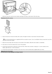
Attaching the driv e screws 8. Connect the second power connector to the drive holder. 9. RZ series m odel equipped with your drive. ...holder with pin 1 on the inside of the drive bay. 7. See the instructions supplied with Giga Pocket) Page 59 Your new hard disk drive is supplied with screws, through the holes on the drive holder tab to align pin 1 on...these screws when securing the drive to the new drive. Replacing the driv e holder (PCV- Connect the second drive connector to the drive holder with the necessary screws. Slide the new drive into position. 11...
Attaching the driv e screws 8. Connect the second power connector to the drive holder. 9. RZ series m odel equipped with your drive. ...holder with pin 1 on the inside of the drive bay. 7. See the instructions supplied with Giga Pocket) Page 59 Your new hard disk drive is supplied with screws, through the holes on the drive holder tab to align pin 1 on...these screws when securing the drive to the new drive. Replacing the driv e holder (PCV- Connect the second drive connector to the drive holder with the necessary screws. Slide the new drive into position. 11...

Online Help Center
Page 71
...VAIO Computer Functions My computer does not start. Check that the computer is plugged into a power source and turned on . Check that the power light is lit on the front panel of the computer. Confirm that a disk is not in the floppy disk drive (unless you plugged the computer into a power strip or Uninterruptible Power Supply... (UPS), make sure the power strip or UPS is turned on and working. Check that the monitor is plugged into a power source and that the brightness and...
...VAIO Computer Functions My computer does not start. Check that the computer is plugged into a power source and turned on . Check that the power light is lit on the front panel of the computer. Confirm that a disk is not in the floppy disk drive (unless you plugged the computer into a power strip or Uninterruptible Power Supply... (UPS), make sure the power strip or UPS is turned on and working. Check that the monitor is plugged into a power source and that the brightness and...

Online Help Center
Page 72
... using a bootable floppy disk). Confirm that a CD is not in stand by mode. About VAIO Computer Functions My computer does not start. Check that the computer is plugged into a power strip or Uninterruptible Power Supply (UPS), make sure the power strip or UPS is turned on and working. Check that the monitor is not in...
... using a bootable floppy disk). Confirm that a CD is not in stand by mode. About VAIO Computer Functions My computer does not start. Check that the computer is plugged into a power strip or Uninterruptible Power Supply (UPS), make sure the power strip or UPS is turned on and working. Check that the monitor is not in...

Online Help Center
Page 109
... surge protector prevents damage to your data during an electrical storm. If you may be using the computer for 10 minutes. This device prevents damage to open the power supply. There are no user-serviceable parts in an area that may want to qualified personnel only. To avoid personal injury or damage...
... surge protector prevents damage to your data during an electrical storm. If you may be using the computer for 10 minutes. This device prevents damage to open the power supply. There are no user-serviceable parts in an area that may want to qualified personnel only. To avoid personal injury or damage...

Online Help Center
Page 116
... occur. VAIO Computer User Guide - This support resource offers a variety of the V A I O C omputer U s er Guide is supplied with Sony, and establish a dial-up your computer's hardware configuration and preinstalled...power cords, cables and peripheral devices, register your VAIO computer. Click VAIO User Guide. Specifications - You can view your computer. Click Welcome from the s ubmenu. In these support options: VAIO® Computer Quick Start - Locate the link in the text, "View the VAIO® Computer Specifications, which describes your computer...
... occur. VAIO Computer User Guide - This support resource offers a variety of the V A I O C omputer U s er Guide is supplied with Sony, and establish a dial-up your computer's hardware configuration and preinstalled...power cords, cables and peripheral devices, register your VAIO computer. Click VAIO User Guide. Specifications - You can view your computer. Click Welcome from the s ubmenu. In these support options: VAIO® Computer Quick Start - Locate the link in the text, "View the VAIO® Computer Specifications, which describes your computer...

Quick Start Guide
Page 6
... Keyboard Mouse Power Cord * The supplied speakers may not be supplied with all of the accessories shown, depending on supplied accessories. 6 Computer and supplied accessories System Unit Speakers* (PCVA-SP3) with AC Adapter Speakers* (PCVA-SP3A) with your computer, see the online Specifications sheet. VAIO Digital Studio Computer Quick Start Unpacking Your Computer Your computer may vary, depending on the VAIO computer model...
... Keyboard Mouse Power Cord * The supplied speakers may not be supplied with all of the accessories shown, depending on supplied accessories. 6 Computer and supplied accessories System Unit Speakers* (PCVA-SP3) with AC Adapter Speakers* (PCVA-SP3A) with your computer, see the online Specifications sheet. VAIO Digital Studio Computer Quick Start Unpacking Your Computer Your computer may vary, depending on the VAIO computer model...

Quick Start Guide
Page 13
...) ports (4) Connection for compatible USB devices. 8 Microphone jack Connection for the supplied speakers or optional headphones. See the online specification sheet for the supplied modem cable to the wall jack. * The speaker model supplied with (Network) is for LAN connections only.) 14 Monitor (DVI) port (...vary between models) Connection for a standard display. 10 Telephone jack Connection for a telephone cable (optional) to the computer. 11 AC Input port Connection for the supplied power cord. 12 Speaker DC Out jack (For use with PCVA-SP3A speakers*) Connection for the speaker...
...) ports (4) Connection for compatible USB devices. 8 Microphone jack Connection for the supplied speakers or optional headphones. See the online specification sheet for the supplied modem cable to the wall jack. * The speaker model supplied with (Network) is for LAN connections only.) 14 Monitor (DVI) port (...vary between models) Connection for a standard display. 10 Telephone jack Connection for a telephone cable (optional) to the computer. 11 AC Input port Connection for the supplied power cord. 12 Speaker DC Out jack (For use with PCVA-SP3A speakers*) Connection for the speaker...

Quick Start Guide
Page 38
... optical drive (unless you plugged the computer into a power strip or Uninterruptible Power Supply (UPS), make sure the power strip or UPS is turned on and working. ❑ Check that the monitor is plugged into a power source and that it is turned on . VAIO Digital Studio Computer Quick Start About VAIO Computer Functions My computer does not start. ❑ Check that...
... optical drive (unless you plugged the computer into a power strip or Uninterruptible Power Supply (UPS), make sure the power strip or UPS is turned on and working. ❑ Check that the monitor is plugged into a power source and that it is turned on . VAIO Digital Studio Computer Quick Start About VAIO Computer Functions My computer does not start. ❑ Check that...

Quick Start Guide
Page 58
...in the text, "View the VAIO® Computer Specifications, which describes your computer quickly and easily. The Quick Start contains information on how to plan an ergonomic work space, connect power cords, cables and peripheral devices, register your computer with Sony, and establish a dial-up...-sensitive search features. This support resource offers a variety of the VAIO Computer User Guide is supplied with selected models. 58 The VAIO Help and Support Center menu appears. 3 Click VAIO User Guide. ❑ Specifications - Your computer is provided with these support options: ❑...
...in the text, "View the VAIO® Computer Specifications, which describes your computer quickly and easily. The Quick Start contains information on how to plan an ergonomic work space, connect power cords, cables and peripheral devices, register your computer with Sony, and establish a dial-up...-sensitive search features. This support resource offers a variety of the VAIO Computer User Guide is supplied with selected models. 58 The VAIO Help and Support Center menu appears. 3 Click VAIO User Guide. ❑ Specifications - Your computer is provided with these support options: ❑...

Marketing Specifications
Page 1
...Sony Desktop Computer are subject to 1.5GB) HARD DRIVE 80GB†† Ultra ATA/100 Hard Drive CD-RW DRIVE CD-RW (32X max. This personal computer is compatible with 10Base-T/100Base-TX Fast Ethernet ¾ i.LINK® (IEEE 1394) Interfaces and 6 USB 2.0 Connectors1 i.LINK® (IEEE 1394) SPECIFICATIONS MODEL PCV-RX850... (front) One Headphone / One Microphone One Line In SUPPLIED ACCESSORIES Speakers (Stereo) VAIO Smart™ Keyboard PS/2® Wheel Mouse RJ-11 Phone Cord POWER REQUIREMENTS 100-120V -3A (50/60Hz) POWER MANAGEMENT ACPI 1.0 Compliant DIMENSIONS (CPU) 8.0"(W) x 14...
...Sony Desktop Computer are subject to 1.5GB) HARD DRIVE 80GB†† Ultra ATA/100 Hard Drive CD-RW DRIVE CD-RW (32X max. This personal computer is compatible with 10Base-T/100Base-TX Fast Ethernet ¾ i.LINK® (IEEE 1394) Interfaces and 6 USB 2.0 Connectors1 i.LINK® (IEEE 1394) SPECIFICATIONS MODEL PCV-RX850... (front) One Headphone / One Microphone One Line In SUPPLIED ACCESSORIES Speakers (Stereo) VAIO Smart™ Keyboard PS/2® Wheel Mouse RJ-11 Phone Cord POWER REQUIREMENTS 100-120V -3A (50/60Hz) POWER MANAGEMENT ACPI 1.0 Compliant DIMENSIONS (CPU) 8.0"(W) x 14...


