
Operating Instructions
Page 1
3-212-686-13(1) LCD Digital Color TV Operating Instructions KDL-40V3000 KDL-46V3000 © 2007 Sony Corporation
3-212-686-13(1) LCD Digital Color TV Operating Instructions KDL-40V3000 KDL-46V3000 © 2007 Sony Corporation
Operating Instructions
Page 2
... allow you are designed to FCC regulations, you call upon your area depends on page 4. s Avoid operating the TV at the rear of the TV. KDL-40V3000 KDL-46V3000 Sony Wall-Mount Bracket Mode No. Note This television includes a QAM demodulator which can be blurred or show poor color due to operate this manual could ...
... allow you are designed to FCC regulations, you call upon your area depends on page 4. s Avoid operating the TV at the rear of the TV. KDL-40V3000 KDL-46V3000 Sony Wall-Mount Bracket Mode No. Note This television includes a QAM demodulator which can be blurred or show poor color due to operate this manual could ...
Operating Instructions
Page 42
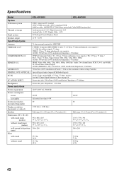
... KDL-46V3000 System Television system NTSC: American TV standard ATSC (8VSB terrestrial): ATSC compliant 8VSB QAM on cable: ANSI/SCTE 07 2000 (Does not include CableCARD functionality) Channel coverage Analog terrestrial: 2-69 / Digital terrestrial: 2-69 Analog Cable: 1-125 / Digital Cable: 1-135 Panel system LCD (Liquid Crystal Display) Panel Speaker output 11 W + 11 W Input/Output...
... KDL-46V3000 System Television system NTSC: American TV standard ATSC (8VSB terrestrial): ATSC compliant 8VSB QAM on cable: ANSI/SCTE 07 2000 (Does not include CableCARD functionality) Channel coverage Analog terrestrial: 2-69 / Digital terrestrial: 2-69 Analog Cable: 1-125 / Digital Cable: 1-135 Panel system LCD (Liquid Crystal Display) Panel Speaker output 11 W + 11 W Input/Output...
Operating Instructions
Page 43
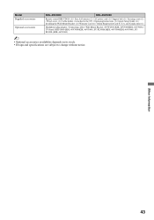
... belt (1) / Securing screw (1) / Wood screw (1) / Cable holder (1 attached to change without notice. and Canada only) (1) Headphones plug adapter / Connecting cables / Wall-Mount Bracket: SU-WL500 (KDL-40V3000/KDL-46V3000) / TV-Stand: RHT-G800 (KDL-40V3000/KDL-46V3000), SU-FL300M (KDL-40V3000/KDL-46V3000), SUFL300L (KDL-46V3000) ~ • Optional accessories availability depends on its stock. • Design and specifications are subject to the...
... belt (1) / Securing screw (1) / Wood screw (1) / Cable holder (1 attached to change without notice. and Canada only) (1) Headphones plug adapter / Connecting cables / Wall-Mount Bracket: SU-WL500 (KDL-40V3000/KDL-46V3000) / TV-Stand: RHT-G800 (KDL-40V3000/KDL-46V3000), SU-FL300M (KDL-40V3000/KDL-46V3000), SUFL300L (KDL-46V3000) ~ • Optional accessories availability depends on its stock. • Design and specifications are subject to the...
Service Manual
Page 1
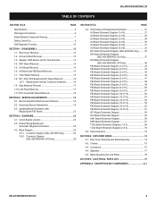
... 34, 37, 40, 43, 45, 59, & 69. 9-883-756-03 LCD DIGITAL COLOR TELEVISION Replaced page 11. Updated schematic diagrams to 8,499,999 and 8,600,001 on up side down. HISTORY INFORMATION FOR THE FOLLOWING MANUAL: SERVICE MANUAL FIX2 CHASSIS MODEL NAME REMOTE COMMANDER DESTINATION KDL-40V3000 KDL-40V3000 KDL-46V3000 KDL-46V3000 KDL-46VL130 RM-YD014 RM...9/2007 10/2007 SUBJECT No revisions or updates are applicable at this time. Updated Self Check illustration. Replaced page 75 & 78. Added PNs for LCD Panels and FB3 Boards for S/N 8,100,001 to correct connector pins #s that were up .
... 34, 37, 40, 43, 45, 59, & 69. 9-883-756-03 LCD DIGITAL COLOR TELEVISION Replaced page 11. Updated schematic diagrams to 8,499,999 and 8,600,001 on up side down. HISTORY INFORMATION FOR THE FOLLOWING MANUAL: SERVICE MANUAL FIX2 CHASSIS MODEL NAME REMOTE COMMANDER DESTINATION KDL-40V3000 KDL-40V3000 KDL-46V3000 KDL-46V3000 KDL-46VL130 RM-YD014 RM...9/2007 10/2007 SUBJECT No revisions or updates are applicable at this time. Updated Self Check illustration. Replaced page 75 & 78. Added PNs for LCD Panels and FB3 Boards for S/N 8,100,001 to correct connector pins #s that were up .
Service Manual
Page 3
... Board Schematic Diagram (6 of 6 32 DF1 Board Schematic Diagram (KDL-40V3000 Only) ......... 34 DF2 Board Schematic Diagram (KDL-46V3000/46VL130 Only 37 DF3 Board Schematic Diagram (KDL-46V3000/46VL130 Only 40 FB3 Board Schematic Diagram (1 of 15 43 FB3 Board Schematic Diagram... Remote Adjustment Buttons and Indicators 19 2-2. Chassis 75 4-3. Bezel Assembly and LCD Panel 78 SECTION 5: ELECTRICAL PARTS LIST 79 APPENDIX A: ENCRYPTION KEY COMPONENTS A-1 KDL-40V3000/46V3000/46VL130 3 Replacing the Inverter Connector Assembly 16 1-9. Updating Model Information after Replacing...
... Board Schematic Diagram (6 of 6 32 DF1 Board Schematic Diagram (KDL-40V3000 Only) ......... 34 DF2 Board Schematic Diagram (KDL-46V3000/46VL130 Only 37 DF3 Board Schematic Diagram (KDL-46V3000/46VL130 Only 40 FB3 Board Schematic Diagram (1 of 15 43 FB3 Board Schematic Diagram... Remote Adjustment Buttons and Indicators 19 2-2. Chassis 75 4-3. Bezel Assembly and LCD Panel 78 SECTION 5: ELECTRICAL PARTS LIST 79 APPENDIX A: ENCRYPTION KEY COMPONENTS A-1 KDL-40V3000/46V3000/46VL130 3 Replacing the Inverter Connector Assembly 16 1-9. Updating Model Information after Replacing...

Service Manual
Page 4
... license from Dolby Laboratories. This TV incorporates HighDefinition Multimedia Interface (HDMI™ ) technology. "Dolby" and the double-D symbol are subject to Apple Computer, Inc., registered in the U.S.A and other countries. Design and specifications are trademarks of Sony Corporation and/or Sony Computer Entertainment Inc. KDL-40V3000/46V3000/46VL130 SPECIFICATIONS Power Requirements 120V-240V...
... license from Dolby Laboratories. This TV incorporates HighDefinition Multimedia Interface (HDMI™ ) technology. "Dolby" and the double-D symbol are subject to Apple Computer, Inc., registered in the U.S.A and other countries. Design and specifications are trademarks of Sony Corporation and/or Sony Computer Entertainment Inc. KDL-40V3000/46V3000/46VL130 SPECIFICATIONS Power Requirements 120V-240V...
Service Manual
Page 5
...inches 992 x 643 x 122 mm 300 x 200 mm 56 lbs. 25.0 kg 48 lbs. 21.5 kg Television system NTSC American TV Standard ATSC (8VSB terrestrial) ATSC compliant 8VSB QAM on cable ANSI/SCTE 07 2000 Channel coverage Analog 2-69 Terrestrial 1-125 Cable Digital 2-... Antenna 75-ohm external terminal for VHF/UHF Panel System LCD (Liquid Crystal Display) Panel Display Resolution (horizontal x vertical): 1,920 dots x 1,080 lines Screen Size (measured diagonally) KDL-40V3000 - ~40 inches KDL-46V3000 - ~46 inches KDL-46VL130 - ~46 inches KDL-46V3000 KDL-46VL130 11W+11W 21/8 x 61/8 inches 55 x...
...inches 992 x 643 x 122 mm 300 x 200 mm 56 lbs. 25.0 kg 48 lbs. 21.5 kg Television system NTSC American TV Standard ATSC (8VSB terrestrial) ATSC compliant 8VSB QAM on cable ANSI/SCTE 07 2000 Channel coverage Analog 2-69 Terrestrial 1-125 Cable Digital 2-... Antenna 75-ohm external terminal for VHF/UHF Panel System LCD (Liquid Crystal Display) Panel Display Resolution (horizontal x vertical): 1,920 dots x 1,080 lines Screen Size (measured diagonally) KDL-40V3000 - ~40 inches KDL-46V3000 - ~46 inches KDL-46VL130 - ~46 inches KDL-46V3000 KDL-46VL130 11W+11W 21/8 x 61/8 inches 55 x...

Service Manual
Page 12
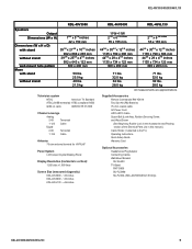
SECTION 1: DISASSEMBLY 1-1. ARM AND STAND REMOVAL 1 Remove 4 screws from Arms, +PSW M5X8 2 Remove 4 screws from Terminals, +BVTP 3X12 TYPE2 IT-3 2 3 1 KDL-40V3000/46V3000/46VL130 Rear Cover 1-2. REAR COVER REMOVAL 1 Remove 15 screws from Rear Cover, +BVTP2 4X16 (KDL-40V3000), Remove 19 screws from Rear Cover, +BVTP2 4X16 (KDL-46V3000/46VL130) 2 Remove 2 screws from Rear Cover arm positions, +PSW M5X12 3 Remove 2 screws from lower stays and Stand, +PSW M5X12 Arm (L) 1 Arm (R) 2 Stand Assembly KDL-40V3000/46V3000/46VL130 12
SECTION 1: DISASSEMBLY 1-1. ARM AND STAND REMOVAL 1 Remove 4 screws from Arms, +PSW M5X8 2 Remove 4 screws from Terminals, +BVTP 3X12 TYPE2 IT-3 2 3 1 KDL-40V3000/46V3000/46VL130 Rear Cover 1-2. REAR COVER REMOVAL 1 Remove 15 screws from Rear Cover, +BVTP2 4X16 (KDL-40V3000), Remove 19 screws from Rear Cover, +BVTP2 4X16 (KDL-46V3000/46VL130) 2 Remove 2 screws from Rear Cover arm positions, +PSW M5X12 3 Remove 2 screws from lower stays and Stand, +PSW M5X12 Arm (L) 1 Arm (R) 2 Stand Assembly KDL-40V3000/46V3000/46VL130 12

Service Manual
Page 14
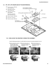
1-5. HV2 BOARD REMOVAL 1 Remove three screws, +BVTP 3X12 TYPE2 IT-3 2 Disconnect two connectors 3 Remove 2 screws, +PVST 3X8 (KDL-40V3000) Remove 2 screws, +PSW M3X5 (KDL-46V3000/46VL130) KDL-40V3000/46V3000/46VL130 1 HV2 Board 2 3 Side Terminal Bracket 1-6 AU BOARD AND FB3 BOARD REMOVAL 1 Slide out Card Bracket 2 Remove 2 screws, +PSW M3X5 3 Remove 2 screws, HEX 4... 7 connectors 7 Disconnect 7 connectors 8 Remove 9 screws, +BVST 3X8 9 Remove 8 screws, +PSW M3X5 Card Bracket 1 4 5 9 2 3 FB Shield (Top) 7 AU Board 8 6 FB3 Board Chassis Bracket KDL-40V3000/46V3000/46VL130 14
1-5. HV2 BOARD REMOVAL 1 Remove three screws, +BVTP 3X12 TYPE2 IT-3 2 Disconnect two connectors 3 Remove 2 screws, +PVST 3X8 (KDL-40V3000) Remove 2 screws, +PSW M3X5 (KDL-46V3000/46VL130) KDL-40V3000/46V3000/46VL130 1 HV2 Board 2 3 Side Terminal Bracket 1-6 AU BOARD AND FB3 BOARD REMOVAL 1 Slide out Card Bracket 2 Remove 2 screws, +PSW M3X5 3 Remove 2 screws, HEX 4... 7 connectors 7 Disconnect 7 connectors 8 Remove 9 screws, +BVST 3X8 9 Remove 8 screws, +PSW M3X5 Card Bracket 1 4 5 9 2 3 FB Shield (Top) 7 AU Board 8 6 FB3 Board Chassis Bracket KDL-40V3000/46V3000/46VL130 14
Service Manual
Page 16
... connected. KDL-40V3000/46V3000/46VL130 16 DF1, DF2, DF3 BOARD AND GF1 BOARD REMOVAL 1 Remove 5 screws, +PSW 3SG (KDL-46V3000 only) 2 Disconnect 3 connectors (KDL-46V3000 only) 3 Disconnect 4 connectors (KDL-40V3000) Disconnect 4 connectors (KDL-46V3000/46VL130) 4 Remove 4 screws, +PSW 3SG 5 Disconnect 7 connectors 6 Remove 4 screws, +PSW 3SG DF1 Board(KDL-40V3000) DF2 Board(KDL-46V3000/46VL130) 5 3 DF3 Board(KDL-46V3000/46VL130) 2 4 1 DF3 Bracket (KDL-46V3000/46VL130) KDL-40V3000/46V3000/46VL130...
... connected. KDL-40V3000/46V3000/46VL130 16 DF1, DF2, DF3 BOARD AND GF1 BOARD REMOVAL 1 Remove 5 screws, +PSW 3SG (KDL-46V3000 only) 2 Disconnect 3 connectors (KDL-46V3000 only) 3 Disconnect 4 connectors (KDL-40V3000) Disconnect 4 connectors (KDL-46V3000/46VL130) 4 Remove 4 screws, +PSW 3SG 5 Disconnect 7 connectors 6 Remove 4 screws, +PSW 3SG DF1 Board(KDL-40V3000) DF2 Board(KDL-46V3000/46VL130) 5 3 DF3 Board(KDL-46V3000/46VL130) 2 4 1 DF3 Bracket (KDL-46V3000/46VL130) KDL-40V3000/46V3000/46VL130...
Service Manual
Page 22
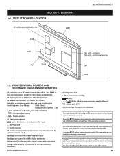
...in 50V unless otherwise specified. sont critiques pour la securite. SECTION 3: DIAGRAMS 3-1. Readings are waveform references. KDL-40V3000/46V3000/46VL130 All voltages are repaired and/or replaced. Replace only with a color-bar signal input. The symbol indicates a ...production tolerances. symbol are taken with a 10MΩ digital multimeter. CIRCUIT BOARDS LOCATION DF3 (KDL-46V3000/46VL130) HW1 FB3 KDL-40V3000/46V3000/46VL130 HV2 AU TUU2 DF1 (KDL-40V3000) DF2 (KDL-46V3000/46VL130) GF1 HW3 3-2. pF : μμF 50WV or less are not indicated except ...
...in 50V unless otherwise specified. sont critiques pour la securite. SECTION 3: DIAGRAMS 3-1. Readings are waveform references. KDL-40V3000/46V3000/46VL130 All voltages are repaired and/or replaced. Replace only with a color-bar signal input. The symbol indicates a ...production tolerances. symbol are taken with a 10MΩ digital multimeter. CIRCUIT BOARDS LOCATION DF3 (KDL-46V3000/46VL130) HW1 FB3 KDL-40V3000/46V3000/46VL130 HV2 AU TUU2 DF1 (KDL-40V3000) DF2 (KDL-46V3000/46VL130) GF1 HW3 3-2. pF : μμF 50WV or less are not indicated except ...

Service Manual
Page 26
CONNECTOR DIAGRAM (KDL-46V3000/46VL130 ONLY) KDL-40V3000/46V3000/46VL130 ፧ᎋᎍ፺ ፹ ᎈ ፧ᎏ፹ KDL-40V3000/46V3000/46VL130 26 3-3-2.
CONNECTOR DIAGRAM (KDL-46V3000/46VL130 ONLY) KDL-40V3000/46V3000/46VL130 ፧ᎋᎍ፺ ፹ ᎈ ፧ᎏ፹ KDL-40V3000/46V3000/46VL130 26 3-3-2.
Service Manual
Page 37
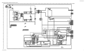
... 6 REG12V 5 GND 4 INV_ERR 3 BACK_LIGHT 2 DIMMER 1 GND 1 GND_3 7 12V 6 FB 5 GND 4 NC 3 LD 2 LD 1 LD CN6701 7P TO BALANCER BAT54HT1 D6625 DF2 INVERTER A-1253-585-A DF2 KDL-40V3000/46V3000/46VL130 37 C - G - H - N - K - L6600 100uH C6600 1 450V PT JW6601 5 JW6602 5 JW6603 5 JW6604 5 S S VCC_12V INV_DRV_1H INV_DRV_1L R6700 4.7 1/10W RN-CP C6789 100 16V 1 GND_3 R6706 10k...
... 6 REG12V 5 GND 4 INV_ERR 3 BACK_LIGHT 2 DIMMER 1 GND 1 GND_3 7 12V 6 FB 5 GND 4 NC 3 LD 2 LD 1 LD CN6701 7P TO BALANCER BAT54HT1 D6625 DF2 INVERTER A-1253-585-A DF2 KDL-40V3000/46V3000/46VL130 37 C - G - H - N - K - L6600 100uH C6600 1 450V PT JW6601 5 JW6602 5 JW6603 5 JW6604 5 S S VCC_12V INV_DRV_1H INV_DRV_1L R6700 4.7 1/10W RN-CP C6789 100 16V 1 GND_3 R6706 10k...
Service Manual
Page 40
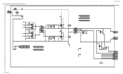
... Mecha A6802 263406661 Q6804,Q6805 O - E - M - TO GF1 BOARD CN6501 CN6800 3P WHT 391.0 PFC_OUT 1 PRI_GND 3 L6800 100uH C6802 1 450V PT C - G - K - I - N - B - F - H - ☛DF3 BOARD SCHEMATIC DIAGRAM (KDL-46V3000/46VL130 ONLY) 1 | 2 | 3 | 4 | 5 | 6 | 7 | 8 | 9 | 10 | 11 | 12 | 13 | 14 | 15 | 16 | 17 | 18 | 19 | 20 | 21 | 22 | 23 | 24 | 25 | 26... 11 V-FB1 10 GND 9 INV-DRV-1H 8 GND 7 INV-DRV-1L 6 GND 5 INV-DRV-2H 4 GND 3 INV-DRV-2L 2 GND 1 1 GND_3 OCP2 A-1253-586-A DF3 P KDL-40V3000/46V3000/46VL130 40
... Mecha A6802 263406661 Q6804,Q6805 O - E - M - TO GF1 BOARD CN6501 CN6800 3P WHT 391.0 PFC_OUT 1 PRI_GND 3 L6800 100uH C6802 1 450V PT C - G - K - I - N - B - F - H - ☛DF3 BOARD SCHEMATIC DIAGRAM (KDL-46V3000/46VL130 ONLY) 1 | 2 | 3 | 4 | 5 | 6 | 7 | 8 | 9 | 10 | 11 | 12 | 13 | 14 | 15 | 16 | 17 | 18 | 19 | 20 | 21 | 22 | 23 | 24 | 25 | 26... 11 V-FB1 10 GND 9 INV-DRV-1H 8 GND 7 INV-DRV-1L 6 GND 5 INV-DRV-2H 4 GND 3 INV-DRV-2L 2 GND 1 1 GND_3 OCP2 A-1253-586-A DF3 P KDL-40V3000/46V3000/46VL130 40
Service Manual
Page 74
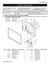
...Sony Electronics Service Information website for any additional service related issues for safety. PART NO. 1 X-2179-890-1 1 X-2179-891-1 2 3 4 * 5 3-106-918-01 3-106-917-11 2-673-535-11 3-210-944-01 DESCRIPTION [ASSEMBLY INCLUDES] REAR COVER ASSEMBLY (40) (KDL-40V3000 ONLY) REAR COVER ASSEMBLY (46) (KDL-46V3000.../46VL130 ONLY) LABEL, REAR TERMINAL LABEL, HDMI SERVICE COVER LABEL, INFORMATION (KDL-40V3000 ONLY) KDL-40V3000/46V3000/46VL130 REF. PART NO. * 5 3-218-...
...Sony Electronics Service Information website for any additional service related issues for safety. PART NO. 1 X-2179-890-1 1 X-2179-891-1 2 3 4 * 5 3-106-918-01 3-106-917-11 2-673-535-11 3-210-944-01 DESCRIPTION [ASSEMBLY INCLUDES] REAR COVER ASSEMBLY (40) (KDL-40V3000 ONLY) REAR COVER ASSEMBLY (46) (KDL-46V3000.../46VL130 ONLY) LABEL, REAR TERMINAL LABEL, HDMI SERVICE COVER LABEL, INFORMATION (KDL-40V3000 ONLY) KDL-40V3000/46V3000/46VL130 REF. PART NO. * 5 3-218-...
Service Manual
Page 75
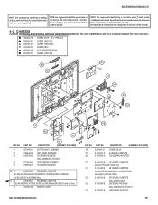
...the back of A-1256-154-B) 62 A-1256-156-B DF1 BOARD, COMPLETE (KDL-40V3000 ONLY) 62 A-1253-585-B DF2 BOARD, MOUNTED (KDL-46V3000/46VL130 ONLY) 63 A-1226-204-B HW3 BOARD, MOUNTED 75 KDL-40V3000/46V3000/46VL130 NOTE: The components identified by a red outline and a mark... contain confidential information. CHASSIS (Check the Sony Electronics Service Information website for any...
...the back of A-1256-154-B) 62 A-1256-156-B DF1 BOARD, COMPLETE (KDL-40V3000 ONLY) 62 A-1253-585-B DF2 BOARD, MOUNTED (KDL-46V3000/46VL130 ONLY) 63 A-1226-204-B HW3 BOARD, MOUNTED 75 KDL-40V3000/46V3000/46VL130 NOTE: The components identified by a red outline and a mark... contain confidential information. CHASSIS (Check the Sony Electronics Service Information website for any...
Service Manual
Page 76
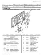
...104 1-910-039-02 EARTH CONNECTOR ASSEMBLY (HV2) 105 1-910-037-40 MO1929 CONNECTOR ASSEMBLY (BF) 20P 106 1-821-375-11 BOARD TO BOARD CONNECTOR 80P 107 1-821-376-11 BOARD TO BOARD CONNECTOR 50P KDL-40V3000/46V3000/46VL130 REF. NO. NO. NOTE: The components identified by... shading and ! CONNECTORS (Check the Sony Electronics Service Information website for any additional service related issues for "Replacing the Inverter ...
...104 1-910-039-02 EARTH CONNECTOR ASSEMBLY (HV2) 105 1-910-037-40 MO1929 CONNECTOR ASSEMBLY (BF) 20P 106 1-821-375-11 BOARD TO BOARD CONNECTOR 80P 107 1-821-376-11 BOARD TO BOARD CONNECTOR 50P KDL-40V3000/46V3000/46VL130 REF. NO. NO. NOTE: The components identified by... shading and ! CONNECTORS (Check the Sony Electronics Service Information website for any additional service related issues for "Replacing the Inverter ...
Service Manual
Page 77
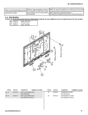
...KDL-46V3000/46VL130 ONLY) REF. NO. Specific instructions must be adhered to whenever these components are critical for this manual. 4-4. KDL-40V3000/46V3000/46VL130 NOTE: The components identified by a red outline and a mark contain confidential information. SPEAKERS (Check the Sony...152 1-826-699-11 152 1-826-702-11 DESCRIPTION [ASSEMBLY INCLUDES] LOUDSPEAKER (4.2X15CM) (KDL-40V3000 ONLY) LOUD SPEAKER (5.5X15.5CM) (KDL-46V3000/46VL130 ONLY) KDL-40V3000/46V3000/46VL130 77 Ne les remplacer que par une piece portant le numero specifie. sont critiques ...
...KDL-46V3000/46VL130 ONLY) REF. NO. Specific instructions must be adhered to whenever these components are critical for this manual. 4-4. KDL-40V3000/46V3000/46VL130 NOTE: The components identified by a red outline and a mark contain confidential information. SPEAKERS (Check the Sony...152 1-826-699-11 152 1-826-702-11 DESCRIPTION [ASSEMBLY INCLUDES] LOUDSPEAKER (4.2X15CM) (KDL-40V3000 ONLY) LOUD SPEAKER (5.5X15.5CM) (KDL-46V3000/46VL130 ONLY) KDL-40V3000/46V3000/46VL130 77 Ne les remplacer que par une piece portant le numero specifie. sont critiques ...
Service Manual
Page 78
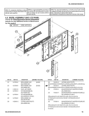
... ASSEMBLY (40)H (KDL-40V3000 ONLY) BEZEL ASSEMBLY (46)H (KDL-46V3000 ONLY) GUIDE, LIGHT SENSOR SP COVER ASSEMBLY(40) (KDL-40V3000 ONLY) SP COVER ASSEMBLY(46) (KDL-46V3000/46VL130 ONLY) BEZEL ASSEMBLY (46) (KDL-46VL130 ONLY) LCD PANEL (40INCH FHD TFT) (KDL-40V3000 ONLY) [202-203] [202-203] KDL-40V3000/46V3000/46VL130 REF... part number specified. NO. KDL-40V3000/46V3000/46VL130 NOTE: The components identified by a red outline and a mark contain confidential information. BEZEL ASSEMBLY AND LCD PANEL (Check the Sony Electronics Service Information website for any additional ...
... ASSEMBLY (40)H (KDL-40V3000 ONLY) BEZEL ASSEMBLY (46)H (KDL-46V3000 ONLY) GUIDE, LIGHT SENSOR SP COVER ASSEMBLY(40) (KDL-40V3000 ONLY) SP COVER ASSEMBLY(46) (KDL-46V3000/46VL130 ONLY) BEZEL ASSEMBLY (46) (KDL-46VL130 ONLY) LCD PANEL (40INCH FHD TFT) (KDL-40V3000 ONLY) [202-203] [202-203] KDL-40V3000/46V3000/46VL130 REF... part number specified. NO. KDL-40V3000/46V3000/46VL130 NOTE: The components identified by a red outline and a mark contain confidential information. BEZEL ASSEMBLY AND LCD PANEL (Check the Sony Electronics Service Information website for any additional ...


