Service Manual
Page 3
...) ......... 34 DF2 Board Schematic Diagram (KDL-46V3000/46VL130 Only 37 DF3 Board Schematic Diagram (KDL-46V3000/46VL130 Only 40 FB3 Board Schematic Diagram (1 of 15 43 FB3 Board Schematic Diagram (2 of 15 44 FB3 Board Schematic Diagram (3... 1: DISASSEMBLY 12 1-1. Block Diagram 24 3-3-1. Replacing the Inverter Connector Assembly 16 1-9. Connectors 76 4-4. Remote Adjustment Buttons and Indicators 19 2-2. Accessing Service Adjustments 19 2-3. TUU2 Board Removal 15 1-8. Stay (Bracket) Removal 17 1-10.LCD Panel Removal 17 1-11. Circuit Boards Location 22 3-2. Semiconductors 73 ...
...) ......... 34 DF2 Board Schematic Diagram (KDL-46V3000/46VL130 Only 37 DF3 Board Schematic Diagram (KDL-46V3000/46VL130 Only 40 FB3 Board Schematic Diagram (1 of 15 43 FB3 Board Schematic Diagram (2 of 15 44 FB3 Board Schematic Diagram (3... 1: DISASSEMBLY 12 1-1. Block Diagram 24 3-3-1. Replacing the Inverter Connector Assembly 16 1-9. Connectors 76 4-4. Remote Adjustment Buttons and Indicators 19 2-2. Accessing Service Adjustments 19 2-3. TUU2 Board Removal 15 1-8. Stay (Bracket) Removal 17 1-10.LCD Panel Removal 17 1-11. Circuit Boards Location 22 3-2. Semiconductors 73 ...
Service Manual
Page 16
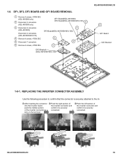
...only) 2 Disconnect 3 connectors (KDL-46V3000 only) 3 Disconnect 4 connectors (KDL-40V3000) Disconnect 4 connectors (KDL-46V3000/46VL130) 4 Remove 4 screws, +PSW 3SG 5 Disconnect 7 connectors 6 Remove 4 screws, +PSW 3SG DF1 Board(KDL-40V3000) DF2 Board(KDL-46V3000/46VL130) 5 3 DF3 Board(KDL-46V3000/46VL130) 2 4... 1 DF3 Bracket (KDL-46V3000/46VL130) KDL-40V3000/46V3000/46VL130 6 GF1 Board G/D Bracket 1-8-1. REPLACING THE INVERTER CONNECTOR ASSEMBLY Use ...
...only) 2 Disconnect 3 connectors (KDL-46V3000 only) 3 Disconnect 4 connectors (KDL-40V3000) Disconnect 4 connectors (KDL-46V3000/46VL130) 4 Remove 4 screws, +PSW 3SG 5 Disconnect 7 connectors 6 Remove 4 screws, +PSW 3SG DF1 Board(KDL-40V3000) DF2 Board(KDL-46V3000/46VL130) 5 3 DF3 Board(KDL-46V3000/46VL130) 2 4... 1 DF3 Bracket (KDL-46V3000/46VL130) KDL-40V3000/46V3000/46VL130 6 GF1 Board G/D Bracket 1-8-1. REPLACING THE INVERTER CONNECTOR ASSEMBLY Use ...
Service Manual
Page 18
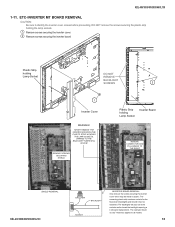
... the fluorescent backlights and should never be metal or plastic. The backlights will pop out of the sockets and/or break the backlight requiring a LCD panel replacement. ETC-INVERTER MT BOARD REMOVAL CAUTION: Be sure to all models. 18 DAMAGE TO THE BACKLIGHT TUBES WILL OCCUR!
... the fluorescent backlights and should never be metal or plastic. The backlights will pop out of the sockets and/or break the backlight requiring a LCD panel replacement. ETC-INVERTER MT BOARD REMOVAL CAUTION: Be sure to all models. 18 DAMAGE TO THE BACKLIGHT TUBES WILL OCCUR!


