Operating Instructions
Page 6
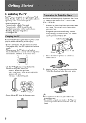
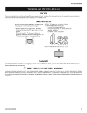
...TV. For product protection and safety reasons, Sony strongly recommends that you install the TV unit to protect your property and avoid causing serious injury. • Before carrying the TV, disconnect all cables. • Carrying the large size TV... force. Installing the TV This TV can be mounted on a wall using a WallMount Bracket or placed on the LCD panel. 3 Gently slide the TV unit onto the neck...the TV • Preparation for a Table-Top stand • Preparation for Table-Top Stand Follow the assembling steps required to place on a TV stand (except models: KDL-52V4100 and KDL-...
...TV. For product protection and safety reasons, Sony strongly recommends that you install the TV unit to protect your property and avoid causing serious injury. • Before carrying the TV, disconnect all cables. • Carrying the large size TV... force. Installing the TV This TV can be mounted on a wall using a WallMount Bracket or placed on the LCD panel. 3 Gently slide the TV unit onto the neck...the TV • Preparation for a Table-Top stand • Preparation for Table-Top Stand Follow the assembling steps required to place on a TV stand (except models: KDL-52V4100 and KDL-...
Operating Instructions
Page 44
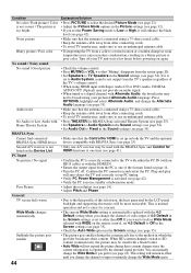
... sound is connected using a 75-ohm coaxial cable. • Keep the antenna cable away from other connecting cords. • To avoid TV interference, make sure to TV Speakers in the Sound settings (see page 34). • Set Audio Out to select the desired Picture Mode (see page 34). Home ...that the antenna is not output from a cold to the thin profile of this television, the heat generated by the LCD panel backlight and supporting electronics will auto-detect the TV and correctly set to Low or High, it will remain in which the provider broadcasts their content. Confirm the PC...
... sound is connected using a 75-ohm coaxial cable. • Keep the antenna cable away from other connecting cords. • To avoid TV interference, make sure to TV Speakers in the Sound settings (see page 34). • Set Audio Out to select the desired Picture Mode (see page 34). Home ...that the antenna is not output from a cold to the thin profile of this television, the heat generated by the LCD panel backlight and supporting electronics will auto-detect the TV and correctly set to Low or High, it will remain in which the provider broadcasts their content. Confirm the PC...
Operating Instructions
Page 46
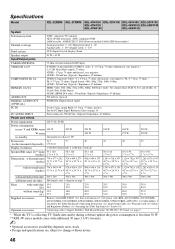
... models less than 0.1 W* Screen size 31.5 37 40 42 46 52 (inches measured diagonally) (32 class) Display resolution 1,920 dots (horizontal...KDL-32XBR6 KDL-37XBR6 KDL-40V4150 KDL-42V4100 KDL-46V4100 KDL-52V4100 KDL-40V4100 KDL-46W4100 KDL-52W4100 KDL-40W4100 KDL-46W4150 System Television system NTSC: American TV standard ATSC (8VSB terrestrial): ATSC compliant 8VSB QAM on cable: ANSI/SCTE 07 2000 (Does not include CableCARD functionality) Channel coverage Analog terrestrial: 2 - 69 / Digital terrestrial: 2 - 69 Analog Cable: 1 - 135 / Digital Cable: 1 - 135 Panel system LCD...
... models less than 0.1 W* Screen size 31.5 37 40 42 46 52 (inches measured diagonally) (32 class) Display resolution 1,920 dots (horizontal...KDL-32XBR6 KDL-37XBR6 KDL-40V4150 KDL-42V4100 KDL-46V4100 KDL-52V4100 KDL-40V4100 KDL-46W4100 KDL-52W4100 KDL-40W4100 KDL-46W4150 System Television system NTSC: American TV standard ATSC (8VSB terrestrial): ATSC compliant 8VSB QAM on cable: ANSI/SCTE 07 2000 (Does not include CableCARD functionality) Channel coverage Analog terrestrial: 2 - 69 / Digital terrestrial: 2 - 69 Analog Cable: 1 - 135 / Digital Cable: 1 - 135 Panel system LCD...
Service Manual
Page 3
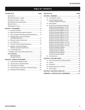
... Removal 17 1-9. Using the Remote Commander to Factory Defaults 54 SECTION TITLE PAGE SECTION 3: DIAGRAMS 55 3-1. Bezel Assembly and LCD Panel 86 4-5. AC Inlet Removal 15 1-7. Printed Wiring Boards and Schematic Diagrams Information 55 3-3. G5 Board (Power Unit) and D4Z... DISASSEMBLY 13 1-1. Side Jack Bracket, BU Shield and BU Board Removal........ 14 1-4. LCD Panel Removal 17 1-10.Balancer (ETC-Inverter MT) Board Removal 18 WIRE DRESSING 19 KDL-52V4100 Only 19 KDL-52W4100 Only 35 SECTION 2: SERVICE ADJUSTMENTS 53 2-1. Circuit Boards Location 55 3-2. Block ...
... Removal 17 1-9. Using the Remote Commander to Factory Defaults 54 SECTION TITLE PAGE SECTION 3: DIAGRAMS 55 3-1. Bezel Assembly and LCD Panel 86 4-5. AC Inlet Removal 15 1-7. Printed Wiring Boards and Schematic Diagrams Information 55 3-3. G5 Board (Power Unit) and D4Z... DISASSEMBLY 13 1-1. Side Jack Bracket, BU Shield and BU Board Removal........ 14 1-4. LCD Panel Removal 17 1-10.Balancer (ETC-Inverter MT) Board Removal 18 WIRE DRESSING 19 KDL-52V4100 Only 19 KDL-52W4100 Only 35 SECTION 2: SERVICE ADJUSTMENTS 53 2-1. Circuit Boards Location 55 3-2. Block ...
Service Manual
Page 5
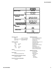
KDL-52V4100/52W4100 Speaker Output KDL-52V4100 KDL-52W4100 10W+10W mm in Dimensions (W x H x D) with stand mm in without stand mm in wall-mount hole pattern wall-mount screw size Mass with stand ... LCD (Liquid Crystal Display) Panel Display Resolution (horizontal x vertical) 1,920 dots x 1,080 lines Screen Size (measured diagonally) ~ 52 inches Supplied Accessories Remote Commander RM-YD023 Two Size AA (R6) Batteries AC Power Cord HD15-HD15 Cable Cable Holder (1 attached to the TV) Operating Instructions Quick Setup Guide Installing the Wall-Mount Bracket Warranty Card...
KDL-52V4100/52W4100 Speaker Output KDL-52V4100 KDL-52W4100 10W+10W mm in Dimensions (W x H x D) with stand mm in without stand mm in wall-mount hole pattern wall-mount screw size Mass with stand ... LCD (Liquid Crystal Display) Panel Display Resolution (horizontal x vertical) 1,920 dots x 1,080 lines Screen Size (measured diagonally) ~ 52 inches Supplied Accessories Remote Commander RM-YD023 Two Size AA (R6) Batteries AC Power Cord HD15-HD15 Cable Cable Holder (1 attached to the TV) Operating Instructions Quick Setup Guide Installing the Wall-Mount Bracket Warranty Card...
Service Manual
Page 6
... the TV, place your palm directly property and avoid causing serious injury. Follow these components with Sony parts whose part numbers appear as illustrated and hold it securely. underneath the panel but do so. An isolation transformer should be used during any servicing other than that are critical for safe operation. KDL-52V4100/52W4100 6 KDL-52V4100/52W4100...
... the TV, place your palm directly property and avoid causing serious injury. Follow these components with Sony parts whose part numbers appear as illustrated and hold it securely. underneath the panel but do so. An isolation transformer should be used during any servicing other than that are critical for safe operation. KDL-52V4100/52W4100 6 KDL-52V4100/52W4100...
Service Manual
Page 8
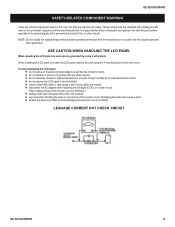
... connectors of the inverter circuit. LEAKAGE CURRENT HOT CHECK CIRCUIT KDL-52V4100/52W4100 8 It is essential that are important for an extended period of time. USE CAUTION WHEN HANDLING THE LCD PANEL When repairing the LCD panel, be sure you will void the original parts and labor ...To avoid damaging the LCD panel: do not expose the LCD panel to prevent electric shock, fire, or other hazard. These components are identified with shading and ! KDL-52V4100/52W4100 SAFETY-RELATED COMPONENT WARNING There are critical components used in LCD color TVs that these critical parts ...
... connectors of the inverter circuit. LEAKAGE CURRENT HOT CHECK CIRCUIT KDL-52V4100/52W4100 8 It is essential that are important for an extended period of time. USE CAUTION WHEN HANDLING THE LCD PANEL When repairing the LCD panel, be sure you will void the original parts and labor ...To avoid damaging the LCD panel: do not expose the LCD panel to prevent electric shock, fire, or other hazard. These components are identified with shading and ! KDL-52V4100/52W4100 SAFETY-RELATED COMPONENT WARNING There are critical components used in LCD color TVs that these critical parts ...
Service Manual
Page 16
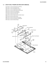
STRUCTURAL FRAMES AND BRACKETS REMOVAL 1 Remove 1 screw from D5 Support and LCD Panel 2 Remove 1 screw from D5 Support Frame 3 Remove 1 screw from Main Bracket and Bezel 4 Remove 3 screws from Main Bracket and Spine frame 5 Remove 2 screws from Top ... from Spine Frames 10 Remove 2 screws from Spine Frames and Bezel 11 Remove 4 screws from both Bottom Vesa Brackets 12 Remove 4 screws from Bottom Bracket KDL-52V4100/52W4100 3 2 D5 Support Frame 1 4 Main Bracket Top Vesa Bracket 5 G Board Suport 8 7 Spine Frame Center 6 Frame 9 Bottom Vesa Bracket 11 10 12 Bottom Bracket Bezel...
STRUCTURAL FRAMES AND BRACKETS REMOVAL 1 Remove 1 screw from D5 Support and LCD Panel 2 Remove 1 screw from D5 Support Frame 3 Remove 1 screw from Main Bracket and Bezel 4 Remove 3 screws from Main Bracket and Spine frame 5 Remove 2 screws from Top ... from Spine Frames 10 Remove 2 screws from Spine Frames and Bezel 11 Remove 4 screws from both Bottom Vesa Brackets 12 Remove 4 screws from Bottom Bracket KDL-52V4100/52W4100 3 2 D5 Support Frame 1 4 Main Bracket Top Vesa Bracket 5 G Board Suport 8 7 Spine Frame Center 6 Frame 9 Bottom Vesa Bracket 11 10 12 Bottom Bracket Bezel...
Service Manual
Page 17
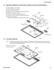
... is attached to the TCON and which side is attached to Wire Dressing Illustration on Page 32 for KDL-52V4100 models or Page 50 for KDL-52W4100 models. 1 Disconnect 3 connectors 2 Remove 2 screws 1 2 LCD Panel Bezel KDL-52V4100/52W4100 17 LCD PANEL REMOVAL Bezel NOTE: The LVDS cable can only be installed one way. Refer to the BU Board. SPEAKERS...
... is attached to the TCON and which side is attached to Wire Dressing Illustration on Page 32 for KDL-52V4100 models or Page 50 for KDL-52W4100 models. 1 Disconnect 3 connectors 2 Remove 2 screws 1 2 LCD Panel Bezel KDL-52V4100/52W4100 17 LCD PANEL REMOVAL Bezel NOTE: The LVDS cable can only be installed one way. Refer to the BU Board. SPEAKERS...

Service Manual
Page 18
.... The backlights will pop out of the sockets and/or break the backlight requiring a LCD panel replacement. 18 KDL-52V4100/52W4100 LCD Panel 2 1 1 Balancer Board Shield WARNING! REMOVE SCREWS SECURING SHIELD REMOVE CONNECTORS AND PULL BOARDS TO THE RIGHT SHIELD REMOVAL KDL-52V4100/52W4100 END VIEW SOCKET BACKLIGHT BALANCER (ETC-INVERTER) BOARD REMOVAL Only remove the screws securing...
.... The backlights will pop out of the sockets and/or break the backlight requiring a LCD panel replacement. 18 KDL-52V4100/52W4100 LCD Panel 2 1 1 Balancer Board Shield WARNING! REMOVE SCREWS SECURING SHIELD REMOVE CONNECTORS AND PULL BOARDS TO THE RIGHT SHIELD REMOVAL KDL-52V4100/52W4100 END VIEW SOCKET BACKLIGHT BALANCER (ETC-INVERTER) BOARD REMOVAL Only remove the screws securing...
Service Manual
Page 19
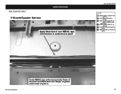
KDL-52V4100 ONLY H Boards/Speaker Harness WIRE DRESSING Apply Sheet Core C over RED UL tape once harness is . KDL-52V4100/52W4100 19 Use Plastic Boss and "dimple" as guides where center of the panel. KDL-52V4100/52W4100 LEGEND SHEET CORE C (2-688-011-01) QTY=11 LCD TAPE (2-688-062-01) QTY=6 SLIDE CLAMP (2-650-770-01) QTY=1 (UPPER VESA SUPPORT) SLIDE CLAMP (2-650-770-11) QTY=12 CHO-FAB TAPE (2-888-494-01) QTY=1 HIMELON TAPE (2-661-260-01) QTY=1 Center RED UL tape on the harness to the Center of panel is centered over panel.
KDL-52V4100 ONLY H Boards/Speaker Harness WIRE DRESSING Apply Sheet Core C over RED UL tape once harness is . KDL-52V4100/52W4100 19 Use Plastic Boss and "dimple" as guides where center of the panel. KDL-52V4100/52W4100 LEGEND SHEET CORE C (2-688-011-01) QTY=11 LCD TAPE (2-688-062-01) QTY=6 SLIDE CLAMP (2-650-770-01) QTY=1 (UPPER VESA SUPPORT) SLIDE CLAMP (2-650-770-11) QTY=12 CHO-FAB TAPE (2-888-494-01) QTY=1 HIMELON TAPE (2-661-260-01) QTY=1 Center RED UL tape on the harness to the Center of panel is centered over panel.
Service Manual
Page 21
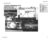
Center tape over Cut-out on Harness Assy. Apply LCD TAPE over BLACK UL TAPE on side of where to align LCD Tape. KDL-52V4100 ONLY Combination H Boards/Speaker Harness Detail of panel edge Apply Sheet Core C over panel sharp edge. 4 KDL-52V4100/52W4100 LEGEND SHEET CORE C (2-688-011-01) QTY=11 LCD TAPE (2-688-062-01) QTY=6 SLIDE CLAMP (2-650-770-01) QTY=1 (UPPER VESA SUPPORT) SLIDE CLAMP (2-650-770-11) QTY=12 CHO-FAB TAPE (2-888-494-01) QTY=1 HIMELON TAPE (2-661-260-01) QTY=1 1 2 KDL-52V4100/52W4100 21
Center tape over Cut-out on Harness Assy. Apply LCD TAPE over BLACK UL TAPE on side of where to align LCD Tape. KDL-52V4100 ONLY Combination H Boards/Speaker Harness Detail of panel edge Apply Sheet Core C over panel sharp edge. 4 KDL-52V4100/52W4100 LEGEND SHEET CORE C (2-688-011-01) QTY=11 LCD TAPE (2-688-062-01) QTY=6 SLIDE CLAMP (2-650-770-01) QTY=1 (UPPER VESA SUPPORT) SLIDE CLAMP (2-650-770-11) QTY=12 CHO-FAB TAPE (2-888-494-01) QTY=1 HIMELON TAPE (2-661-260-01) QTY=1 1 2 KDL-52V4100/52W4100 21

Service Manual
Page 23
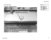
KDL-52V4100/52W4100 LEGEND SHEET CORE C (2-688-011-01) QTY=11 LCD TAPE (2-688-062-01) QTY=6 SLIDE CLAMP (2-650-770-01) QTY=1 (UPPER VESA SUPPORT) SLIDE CLAMP (2-650-770-11) QTY=12 CHO-FAB TAPE (2-888-494-01) QTY=1 HIMELON TAPE (2-661-260-01) QTY=1 7 5 6 NOTE DETAIL PHOTO of Conn Assy. Wire are ABOVE plastic CLIP on the connector assy as shown. Use BLACK UL TAPE on panel. KDL-52V4100/52W4100 23 Apply x3 Sheet Core C himelon tape as guide where To place himelon tape. KDL-52V4100 ONLY Balancer Board to D4Z Board 9P Conn Assy.
KDL-52V4100/52W4100 LEGEND SHEET CORE C (2-688-011-01) QTY=11 LCD TAPE (2-688-062-01) QTY=6 SLIDE CLAMP (2-650-770-01) QTY=1 (UPPER VESA SUPPORT) SLIDE CLAMP (2-650-770-11) QTY=12 CHO-FAB TAPE (2-888-494-01) QTY=1 HIMELON TAPE (2-661-260-01) QTY=1 7 5 6 NOTE DETAIL PHOTO of Conn Assy. Wire are ABOVE plastic CLIP on the connector assy as shown. Use BLACK UL TAPE on panel. KDL-52V4100/52W4100 23 Apply x3 Sheet Core C himelon tape as guide where To place himelon tape. KDL-52V4100 ONLY Balancer Board to D4Z Board 9P Conn Assy.

Service Manual
Page 24
KDL-52V4100 ONLY Panel Balancer Board Conn Assy. KDL-52V4100/52W4100 LEGEND SHEET CORE C (2-688-011-01) QTY=11 LCD TAPE (2-688-062-01) QTY=6 SLIDE CLAMP (2-650-770-01) QTY=1 (UPPER VESA SUPPORT) SLIDE CLAMP (2-650-770-11) QTY=12 CHO-FAB TAPE (2-888-494-01) QTY=1 HIMELON TAPE (2-661-260-01) QTY=1 7 With Lower LCD... Bracket installed, Wires will be below level of metal edge as shown if Black UL Tape is Aligned with white plastic pin (as guide for Black UL Tape position. Apply Sheet Core C to secure wires. Detail Use Plastic Pin as shown) KDL-52V4100/52W4100 24 Wires...
KDL-52V4100 ONLY Panel Balancer Board Conn Assy. KDL-52V4100/52W4100 LEGEND SHEET CORE C (2-688-011-01) QTY=11 LCD TAPE (2-688-062-01) QTY=6 SLIDE CLAMP (2-650-770-01) QTY=1 (UPPER VESA SUPPORT) SLIDE CLAMP (2-650-770-11) QTY=12 CHO-FAB TAPE (2-888-494-01) QTY=1 HIMELON TAPE (2-661-260-01) QTY=1 7 With Lower LCD... Bracket installed, Wires will be below level of metal edge as shown if Black UL Tape is Aligned with white plastic pin (as guide for Black UL Tape position. Apply Sheet Core C to secure wires. Detail Use Plastic Pin as shown) KDL-52V4100/52W4100 24 Wires...

Service Manual
Page 28
KDL-52V4100 ONLY Balancer Board Wire Dressing 10 PANEL 6 Balancer-L NEW Hirose MDF-61 Connector on both balancer boards. D4Z Board KDL-52V4100/52W4100 LEGEND SHEET CORE C (2-688-011-01) QTY=11 LCD TAPE (2-688-062-01) QTY=6 SLIDE CLAMP (2-650-770-01) QTY=1 (UPPER VESA SUPPORT) SLIDE CLAMP (2-650-770-11) QTY=12 CHO-FAB TAPE (2-888-494-01) QTY=1 HIMELON TAPE (2-661-260-01) QTY=1 PANEL Balancer-R D5 Board KDL-52V4100/52W4100 28
KDL-52V4100 ONLY Balancer Board Wire Dressing 10 PANEL 6 Balancer-L NEW Hirose MDF-61 Connector on both balancer boards. D4Z Board KDL-52V4100/52W4100 LEGEND SHEET CORE C (2-688-011-01) QTY=11 LCD TAPE (2-688-062-01) QTY=6 SLIDE CLAMP (2-650-770-01) QTY=1 (UPPER VESA SUPPORT) SLIDE CLAMP (2-650-770-11) QTY=12 CHO-FAB TAPE (2-888-494-01) QTY=1 HIMELON TAPE (2-661-260-01) QTY=1 PANEL Balancer-R D5 Board KDL-52V4100/52W4100 28

Service Manual
Page 32
... with 3x5mm Screw is CRITICAL FOR EMI Apply 3x8mm Screw to secure LVDS Cable to panel and BU Board bracket. 2 MAKE SURE clip is CRITICAL FOR EMI 1 3 KDL-52V4100/52W4100 LEGEND SHEET CORE C (2-688-011-01) QTY=11 LCD TAPE (2-688-062-01) QTY=6 SLIDE CLAMP (2-650-770-01) QTY=1 (UPPER VESA ... is centered between Guides on D5 Board. 52V has x3 RED UL Tape bands. 10 8 1 9 Apply 3x5mm Screw to secure LVDS Cable to panel and BU Board bracket. KDL-52V4100 ONLY LVDS Cable Routing/Dress (CRITICAL FOR EMI) See next page for details on Main Bracket BEFORE installing 11 Screw.
... with 3x5mm Screw is CRITICAL FOR EMI Apply 3x8mm Screw to secure LVDS Cable to panel and BU Board bracket. 2 MAKE SURE clip is CRITICAL FOR EMI 1 3 KDL-52V4100/52W4100 LEGEND SHEET CORE C (2-688-011-01) QTY=11 LCD TAPE (2-688-062-01) QTY=6 SLIDE CLAMP (2-650-770-01) QTY=1 (UPPER VESA ... is centered between Guides on D5 Board. 52V has x3 RED UL Tape bands. 10 8 1 9 Apply 3x5mm Screw to secure LVDS Cable to panel and BU Board bracket. KDL-52V4100 ONLY LVDS Cable Routing/Dress (CRITICAL FOR EMI) See next page for details on Main Bracket BEFORE installing 11 Screw.

Service Manual
Page 33
LEGEND SHEET CORE C (2-688-011-01) QTY=11 LCD TAPE (2-688-062-01) QTY=6 SLIDE CLAMP (2-650-770-01) QTY=1 (UPPER VESA SUPPORT) SLIDE CLAMP (2-650-770-11) QTY=12 CHO-FAB TAPE (2-888-... MAKE SURE Himelon tape covers Cho-Fab and that both himelon tape and Cho-Fab tape are firmly taped to panel (EMI CRITICAL) KDL-52V4100/52W4100 33 The tape MUST contact panel/LVDS. KDL-52V4100/52W4100 KDL-52V4100 ONLY LVDS Cable Routing/Dress (CRITICAL FOR EMI) Apply Cho-Fab Tape P/N:2-888-494-01 Over opening in LVDS Cable...
LEGEND SHEET CORE C (2-688-011-01) QTY=11 LCD TAPE (2-688-062-01) QTY=6 SLIDE CLAMP (2-650-770-01) QTY=1 (UPPER VESA SUPPORT) SLIDE CLAMP (2-650-770-11) QTY=12 CHO-FAB TAPE (2-888-... MAKE SURE Himelon tape covers Cho-Fab and that both himelon tape and Cho-Fab tape are firmly taped to panel (EMI CRITICAL) KDL-52V4100/52W4100 33 The tape MUST contact panel/LVDS. KDL-52V4100/52W4100 KDL-52V4100 ONLY LVDS Cable Routing/Dress (CRITICAL FOR EMI) Apply Cho-Fab Tape P/N:2-888-494-01 Over opening in LVDS Cable...
Service Manual
Page 35
KDL-52V4100/52W4100 35 KDL-52W4100 ONLY H Boards / Speaker Harness Apply Sheet Core C over panel. Use Plastic Boss and "dimple" as guides where center of the panel. KDL-52V4100/52W4100 LEGEND SHEET CORE C (2-688-011-01) QTY=12 LCD TAPE (2-688-062-01) QTY=4 SLIDE CLAMP (2-650-770-01) QTY=1 (UPPER VESA SUPPORT) SLIDE CLAMP (2-650-770-11) QTY=11 Center RED UL tape on the harness to the Center of panel is centered over RED UL tape once harness is .
KDL-52V4100/52W4100 35 KDL-52W4100 ONLY H Boards / Speaker Harness Apply Sheet Core C over panel. Use Plastic Boss and "dimple" as guides where center of the panel. KDL-52V4100/52W4100 LEGEND SHEET CORE C (2-688-011-01) QTY=12 LCD TAPE (2-688-062-01) QTY=4 SLIDE CLAMP (2-650-770-01) QTY=1 (UPPER VESA SUPPORT) SLIDE CLAMP (2-650-770-11) QTY=11 Center RED UL tape on the harness to the Center of panel is centered over RED UL tape once harness is .
Service Manual
Page 37
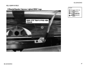
KDL-52W4100 ONLY H Boards/Speaker Harness: Lighted SONY Logo Apply LCD Tape to sharp edge of panel. 1 KDL-52V4100/52W4100 LEGEND SHEET CORE C (2-688-011-01) QTY=12 LCD TAPE (2-688-062-01) QTY=4 SLIDE CLAMP (2-650-770-01) QTY=1 (UPPER VESA SUPPORT) SLIDE CLAMP (2-650-770-11) QTY=11 KDL-52V4100/52W4100 37
KDL-52W4100 ONLY H Boards/Speaker Harness: Lighted SONY Logo Apply LCD Tape to sharp edge of panel. 1 KDL-52V4100/52W4100 LEGEND SHEET CORE C (2-688-011-01) QTY=12 LCD TAPE (2-688-062-01) QTY=4 SLIDE CLAMP (2-650-770-01) QTY=1 (UPPER VESA SUPPORT) SLIDE CLAMP (2-650-770-11) QTY=11 KDL-52V4100/52W4100 37
Service Manual
Page 86
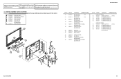
...] (KDL-52V4100 ONLY) BEZEL ASSY (52) [152] (KDL-52W4100 ONLY) EMBLEM, SONY NO.9 (KDL-52V4100 ONLY) LOUDSPEAKER (6.5X15CM) (L) (KDL-52V4100 ONLY) LOUDSPEAKER (3CM, 6.5X15CM) (L) (KDL-52W4100 ONLY) ILLUMINATION MODULE (KDL-52W4100 ONLY) 155 156 * 157 3-290-800-01 A-1494-139-A 3-290-837-01 GUIDE, LIGHT H4 BOARD, MOUNTED PANEL, CLEAR (52) 158... 152 154 155 156 157 160 158 159 161 153 162 163 164 165 KDL-52V4100/52W4100 REF. DESCRIPTION [ASSEMBLY INCLUDES] (FOR KDL-52V4100 ONLY) 161 1-802-651-11 LCD PANEL (52 FHD TFT) [162-165] 162 1-857-048-11 ETC-INVERTER MT BOARD ...
...] (KDL-52V4100 ONLY) BEZEL ASSY (52) [152] (KDL-52W4100 ONLY) EMBLEM, SONY NO.9 (KDL-52V4100 ONLY) LOUDSPEAKER (6.5X15CM) (L) (KDL-52V4100 ONLY) LOUDSPEAKER (3CM, 6.5X15CM) (L) (KDL-52W4100 ONLY) ILLUMINATION MODULE (KDL-52W4100 ONLY) 155 156 * 157 3-290-800-01 A-1494-139-A 3-290-837-01 GUIDE, LIGHT H4 BOARD, MOUNTED PANEL, CLEAR (52) 158... 152 154 155 156 157 160 158 159 161 153 162 163 164 165 KDL-52V4100/52W4100 REF. DESCRIPTION [ASSEMBLY INCLUDES] (FOR KDL-52V4100 ONLY) 161 1-802-651-11 LCD PANEL (52 FHD TFT) [162-165] 162 1-857-048-11 ETC-INVERTER MT BOARD ...

