The Sony Guide to Home Theater
Page 44
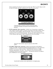
...of video: Red, Green and Blue, abbreviated R/G/B. The Sony Guide to protect the signal from piracy. The D-sub 15-pin interface supports component video R/G/B signals. ƒ DVI-HDTV digital video connection. The DVI-HDTV interface carries High Definition in full digital quality. The physical connector ... quality is most often used for connecting a PC or an LCD front projector. The physical cable usually has a D-sub 15-pin connector that includes a pair of the signal from an HDTV receiver to the television. ƒ R/G/B component video connection. This is separate connections ...
...of video: Red, Green and Blue, abbreviated R/G/B. The Sony Guide to protect the signal from piracy. The D-sub 15-pin interface supports component video R/G/B signals. ƒ DVI-HDTV digital video connection. The DVI-HDTV interface carries High Definition in full digital quality. The physical connector ... quality is most often used for connecting a PC or an LCD front projector. The physical cable usually has a D-sub 15-pin connector that includes a pair of the signal from an HDTV receiver to the television. ƒ R/G/B component video connection. This is separate connections ...

Operating Instructions (Large File - 14.6 MB)
Page 5
...Never subject the chassis to deteriorate. When transporting, do not subject the set with the LCD screen surface since this unit. Ventilation holes Do not insert anything heavy on the AC power cord or display interface cable. For the set . If a person other than the assemblers install the display unit on... on the wall using it and ask your dealer or Sony service center to have a suitable outlet installed. The set may fall and damage the set is not installed securely. If the AC power cord or display interface cable is not being turned on or off when it is ...
...Never subject the chassis to deteriorate. When transporting, do not subject the set with the LCD screen surface since this unit. Ventilation holes Do not insert anything heavy on the AC power cord or display interface cable. For the set . If a person other than the assemblers install the display unit on... on the wall using it and ask your dealer or Sony service center to have a suitable outlet installed. The set may fall and damage the set is not installed securely. If the AC power cord or display interface cable is not being turned on or off when it is ...
Operating Instructions (Large File - 14.6 MB)
Page 11
... 17 TV Controls and Connectors 18 Display Unit 18 Media Receiver Unit Front Panel 20 Media Receiver Unit Rear Panel 22 Installing the TV 23 Storing the AC power cord and the display interface cable inside the stand (KDL32XBR950 only 25 Detaching and attaching the speakers (KDL42XBR950 ...Connections: Connecting a Cable or Antenna 30 Cable or Antenna 30 Cable Box and Cable 31 Cable Box 32 Connecting Optional Equipment 33 About Using S VIDEO 33 VCR and Cable 34 VCR and Cable Box 36 Two VCRs for Tape Editing 38 Satellite Receiver 40 Satellite Receiver and VCR 42 DVD Player with...
... 17 TV Controls and Connectors 18 Display Unit 18 Media Receiver Unit Front Panel 20 Media Receiver Unit Rear Panel 22 Installing the TV 23 Storing the AC power cord and the display interface cable inside the stand (KDL32XBR950 only 25 Detaching and attaching the speakers (KDL42XBR950 ...Connections: Connecting a Cable or Antenna 30 Cable or Antenna 30 Cable Box and Cable 31 Cable Box 32 Connecting Optional Equipment 33 About Using S VIDEO 33 VCR and Cable 34 VCR and Cable Box 36 Two VCRs for Tape Editing 38 Satellite Receiver 40 Satellite Receiver and VCR 42 DVD Player with...
Operating Instructions (Large File - 14.6 MB)
Page 15
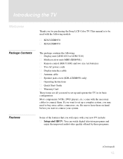
... to connect your new TV include: s Integrated HDTV: You can watch digital television programs and enjoy the improved audio/video quality offered by these programs. (Continued)... the features that you want to set up a complex system, you for purchasing the Sony LCD Color TV. Introducing the TV Welcome Thank you may need to set up and operate the...-XBR950L) s Remote control (RM-Y1000) and two size AA batteries s Two AC power cords s Display interface cable s Antenna cable s Speaker jack covers (KDL42XBR950 only) s Operating Instructions s Quick Start Guide s Warranty Card These items are...
... to connect your new TV include: s Integrated HDTV: You can watch digital television programs and enjoy the improved audio/video quality offered by these programs. (Continued)... the features that you want to set up a complex system, you for purchasing the Sony LCD Color TV. Introducing the TV Welcome Thank you may need to set up and operate the...-XBR950L) s Remote control (RM-Y1000) and two size AA batteries s Two AC power cords s Display interface cable s Antenna cable s Speaker jack covers (KDL42XBR950 only) s Operating Instructions s Quick Start Guide s Warranty Card These items are...

Operating Instructions (Large File - 14.6 MB)
Page 21
... Rear panel KDL42XBR950 KDL32XBR950 Setup SONY EXCLUSIVE CABLE ONLY WHITE DISPLAY SIGNAL IN BLACK AC IN OUTPUT R L OFF ON SONY EXCLUSIVE CABLE ONLY WHITE BLACK DISPLAY SIGNAL IN AC IN Item Description 6 DISPLAY SIGNAL IN Connect to the DISPLAY SIGNAL OUT jacks of the rear of the media receiver unit by using the supplied display interface cable...
... Rear panel KDL42XBR950 KDL32XBR950 Setup SONY EXCLUSIVE CABLE ONLY WHITE DISPLAY SIGNAL IN BLACK AC IN OUTPUT R L OFF ON SONY EXCLUSIVE CABLE ONLY WHITE BLACK DISPLAY SIGNAL IN AC IN Item Description 6 DISPLAY SIGNAL IN Connect to the DISPLAY SIGNAL OUT jacks of the rear of the media receiver unit by using the supplied display interface cable...

Operating Instructions (Large File - 14.6 MB)
Page 24
.... 8 CABLE RF input that has S VIDEO. A third composite A/V input jack (VIDEO 2) is PCM/Dolby Digital compatible. 6 i.LINK 1/3 Used for use these outputs to listen to your VCR or other Sony infrared-controlled audio or video equipment that has the CONTROL S function. 5 DIGITAL ... * "Dolby", "Pro Logic", and the double-D symbol are not intended for details about connecting and using the supplied OUT display interface cable. Use a DVI-D single link cable. Media Receiver Unit Rear Panel 1 2 34 5 67 8 Setup S VIDEO VIDEO L AUDIO R 1 VIDEO IN Y PB PR 3 HD/DVD IN 4Y ...
.... 8 CABLE RF input that has S VIDEO. A third composite A/V input jack (VIDEO 2) is PCM/Dolby Digital compatible. 6 i.LINK 1/3 Used for use these outputs to listen to your VCR or other Sony infrared-controlled audio or video equipment that has the CONTROL S function. 5 DIGITAL ... * "Dolby", "Pro Logic", and the double-D symbol are not intended for details about connecting and using the supplied OUT display interface cable. Use a DVI-D single link cable. Media Receiver Unit Rear Panel 1 2 34 5 67 8 Setup S VIDEO VIDEO L AUDIO R 1 VIDEO IN Y PB PR 3 HD/DVD IN 4Y ...

Operating Instructions (Large File - 14.6 MB)
Page 25
... power cord (supplied) (Continued) 23 KDL32XBR950 AC power cord (supplied) SONY EXCLUSIVE CABLE ONLY WHITE BLACK AC IN DISPLAY SIGNAL IN Display interface cable (supplied) Tighten the screw slowly until the screw is stabilized. KDL42XBR950 Setup SONY EXCLUSIVE CABLE ONLY WHITE BLACK DISPLAY SIGNAL IN Display interface cable (supplied) Tighten the screw slowly until the screw is stabilized.
... power cord (supplied) (Continued) 23 KDL32XBR950 AC power cord (supplied) SONY EXCLUSIVE CABLE ONLY WHITE BLACK AC IN DISPLAY SIGNAL IN Display interface cable (supplied) Tighten the screw slowly until the screw is stabilized. KDL42XBR950 Setup SONY EXCLUSIVE CABLE ONLY WHITE BLACK DISPLAY SIGNAL IN Display interface cable (supplied) Tighten the screw slowly until the screw is stabilized.

Operating Instructions (Large File - 14.6 MB)
Page 26
...use the supplied AC power cords. Do not tighten the screws too much. Handle the display interface cable with care. Setup When you have completed making all connections. Display interface AC power cord cable (supplied) (supplied) 3 After making all connections, connect the AC power cords (supplied)...until you install KDL42XBR950, use one of these optional accessories: s SONY TABLE TOP STAND: SU-P42T2 s SONY WALL-MOUNT BRACKET: SU-PW2 s SONY FLOATING STAND: SU-PF1 2 Connect the other end of display interface cable to the media receiver unit's DISPLAY SIGNAL OUT jacks, and connect...
...use the supplied AC power cords. Do not tighten the screws too much. Handle the display interface cable with care. Setup When you have completed making all connections. Display interface AC power cord cable (supplied) (supplied) 3 After making all connections, connect the AC power cords (supplied)...until you install KDL42XBR950, use one of these optional accessories: s SONY TABLE TOP STAND: SU-P42T2 s SONY WALL-MOUNT BRACKET: SU-PW2 s SONY FLOATING STAND: SU-PF1 2 Connect the other end of display interface cable to the media receiver unit's DISPLAY SIGNAL OUT jacks, and connect...

Operating Instructions (Large File - 14.6 MB)
Page 27
... unit Holes on the top of the display unit Cable cover Setup 3 Store the excess AC power cord and the display interface cable inside the stand (KDL32XBR950 only) You can store the AC power cord and the display interface cable into place. Insert the cable cover into the holes on the bass of the ...stand, then attach the cable cover by pressing the cable cover into the stand by removing the cable cover on the display stand. 1 Press down at the tab...
... unit Holes on the top of the display unit Cable cover Setup 3 Store the excess AC power cord and the display interface cable inside the stand (KDL32XBR950 only) You can store the AC power cord and the display interface cable into place. Insert the cable cover into the holes on the bass of the ...stand, then attach the cable cover by pressing the cable cover into the stand by removing the cable cover on the display stand. 1 Press down at the tab...

Operating Instructions (Large File - 14.6 MB)
Page 126
...Picture option in front of the TV or at the side of detail, especially during s Video head interference. s Make sure the display interface cable is connected to cycle through the connected video sources. Dark, poor or no text is normal for certain digitally recorded programs. Adjust the ...trouble. Dotted lines or stripes s Adjust the antenna. Call your VCR in the Video menu (see page 58). s Avoid installing your local Sony Service Center. "Black box" on the front of Text 1-4. Your TV will show very fine detail, and is available. Certain programs on your...
...Picture option in front of the TV or at the side of detail, especially during s Video head interference. s Make sure the display interface cable is connected to cycle through the connected video sources. Dark, poor or no text is normal for certain digitally recorded programs. Adjust the ...trouble. Dotted lines or stripes s Adjust the antenna. Call your VCR in the Video menu (see page 58). s Avoid installing your local Sony Service Center. "Black box" on the front of Text 1-4. Your TV will show very fine detail, and is available. Certain programs on your...

Operating Instructions (Large File - 14.6 MB)
Page 130
... receiver unit MBD-XBR950L: 53 W In Standby Under 1.5 W i.LINK standby Under 22 W Media receiver unit Remote Control (1) AA (R6) Batteries (2) AC power cord (2) Display interface cable (1) Antenna cable (1) Operating Instructions (1) Quick Start Guide (1) Warranty Card (1) RM-Y1000 Display unit Speaker jack covers (2) (KDL42XBR950 only) Design and specifications are subject to change without notice.
... receiver unit MBD-XBR950L: 53 W In Standby Under 1.5 W i.LINK standby Under 22 W Media receiver unit Remote Control (1) AA (R6) Batteries (2) AC power cord (2) Display interface cable (1) Antenna cable (1) Operating Instructions (1) Quick Start Guide (1) Warranty Card (1) RM-Y1000 Display unit Speaker jack covers (2) (KDL42XBR950 only) Design and specifications are subject to change without notice.

Operating Instructions (Large File - 14.6 MB)
Page 131
Other Info Optional Accessories s DVI-D single link cable s Component video cable s S VIDEO cable s A/V cable s Audio cable s Optical cable s Control S cable: RK-G69 s i.LINK cables: VMC-IL4415 (4-pin to 4-pin, 1.5 meters) VMC-IL4435 (4-pin to 4-pin, 3.5 meters) s Display interface cable: VMC-P10 (10 meters) s Table top stand: SU-P42T2 (for LDM-4210) s Wall-mount bracket: SU-LW1 (for LDM-3210) SU-PW2 (for LDM-4210) s Floating stand: SU-PF1: (for LDM-4210) 129 Other Info
Other Info Optional Accessories s DVI-D single link cable s Component video cable s S VIDEO cable s A/V cable s Audio cable s Optical cable s Control S cable: RK-G69 s i.LINK cables: VMC-IL4415 (4-pin to 4-pin, 1.5 meters) VMC-IL4435 (4-pin to 4-pin, 3.5 meters) s Display interface cable: VMC-P10 (10 meters) s Table top stand: SU-P42T2 (for LDM-4210) s Wall-mount bracket: SU-LW1 (for LDM-3210) SU-PW2 (for LDM-4210) s Floating stand: SU-PF1: (for LDM-4210) 129 Other Info

Operating Instructions (Large File - 14.6 MB)
Page 133
See Digital Visual Interface. DVD player using with A/V connectors, connecting 46 DVI. DVI-HDTV 22, 127 E ENTER button 59 error messages, Memory Stick 122 (Continued) 131 See cable CH buttons 59 changing picture size, in remote control 57 bilingual audio 106 Black Corrector 104 blocking programs. See ratings....78 Digital Caption Setup menu 78 Digital Channels 110 Digital Reality Creation 14 Digital Setup menu 78 Digital Signal Strength 78 Digital Visual Interface (DVI) 15, 22 DISPLAY button 66 DISPLAY SIGNAL OUT, described 22 Display unit connecting 23 controls 18 DRC Function 103 DRC...
See Digital Visual Interface. DVD player using with A/V connectors, connecting 46 DVI. DVI-HDTV 22, 127 E ENTER button 59 error messages, Memory Stick 122 (Continued) 131 See cable CH buttons 59 changing picture size, in remote control 57 bilingual audio 106 Black Corrector 104 blocking programs. See ratings....78 Digital Caption Setup menu 78 Digital Channels 110 Digital Reality Creation 14 Digital Setup menu 78 Digital Signal Strength 78 Digital Visual Interface (DVI) 15, 22 DISPLAY button 66 DISPLAY SIGNAL OUT, described 22 Display unit connecting 23 controls 18 DRC Function 103 DRC...
Quick Start Guide
Page 1
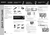
... whenever you to use a cable box), but does not scramble all connections. KDL32XBR950 KDL42XBR950 SONY EXCLUSIVE CABLE ONLY WHITE BLACK DISPLAY SIGNAL IN Tighten the screw Display Interface slowly until the cable (supplied) screw is high. 1 Connect the display interface cable (supplied) to the DISPLAY SIGNAL...KDL42XBR950, use the optional accessories as follows: • SONY TABLE TOP STAND: SU-P42T2 • SONY WALL-MOUNT BRACKET: SU-PW2 • SONY FLOATING STAND: SU-PF1 2 Connect the other end of display interface cable to the media receiver unit's DISPLAY SIGNAL OUT jacks,...
... whenever you to use a cable box), but does not scramble all connections. KDL32XBR950 KDL42XBR950 SONY EXCLUSIVE CABLE ONLY WHITE BLACK DISPLAY SIGNAL IN Tighten the screw Display Interface slowly until the cable (supplied) screw is high. 1 Connect the display interface cable (supplied) to the DISPLAY SIGNAL...KDL42XBR950, use the optional accessories as follows: • SONY TABLE TOP STAND: SU-P42T2 • SONY WALL-MOUNT BRACKET: SU-PW2 • SONY FLOATING STAND: SU-PF1 2 Connect the other end of display interface cable to the media receiver unit's DISPLAY SIGNAL OUT jacks,...
Marketing Specifications
Page 2
... Speakers • Panel System: LCD Display • Screen Size (Diagonally): KDL-42XBR950 = 42 inches KDL-32XBR950 = 32 inches • Display Resolution: KDL-42XBR950 =1366 x 768 KDL-32XBR950 =1280 x 768 • Antenna: 75 Ohm External • TV System: (Media Box) NTSC America TV Tuner • Channel Coverage: VHF 2 - 13 UHF 14 - 69 CATV 1 - 999 ATSC 1 - 99 • Advanced WEGA Engine™...
... Speakers • Panel System: LCD Display • Screen Size (Diagonally): KDL-42XBR950 = 42 inches KDL-32XBR950 = 32 inches • Display Resolution: KDL-42XBR950 =1366 x 768 KDL-32XBR950 =1280 x 768 • Antenna: 75 Ohm External • TV System: (Media Box) NTSC America TV Tuner • Channel Coverage: VHF 2 - 13 UHF 14 - 69 CATV 1 - 999 ATSC 1 - 99 • Advanced WEGA Engine™...

Instructions for stand (primary manual)
Page 4
.... If you install the Display Unit on it. Do not allow the AC power cord or the Display Interface Cable to be pinched. • Do not allow the AC power cord or the Display Interface Cable to be damaged, and this may result in a fire or an electric shock. This stand is carried ... not observed, injury or property damage may fall and cause injury or property damage. If you stumble over the AC power cord or the Display Interface Cable, the Tabletop Stand may fall and cause injury. 4 (US) CAUTION If the following precautions are not used, the Display Unit may occur. The AC power...
.... If you install the Display Unit on it. Do not allow the AC power cord or the Display Interface Cable to be pinched. • Do not allow the AC power cord or the Display Interface Cable to be damaged, and this may result in a fire or an electric shock. This stand is carried ... not observed, injury or property damage may fall and cause injury or property damage. If you stumble over the AC power cord or the Display Interface Cable, the Tabletop Stand may fall and cause injury. 4 (US) CAUTION If the following precautions are not used, the Display Unit may occur. The AC power...
Instructions for stand (primary manual)
Page 7
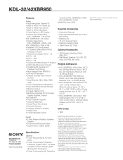
... pinched under or between pieces of the Sony Flat Panel Color Television or LCD Color Television for more details on the Tabletop Stand. 1 Connect the AC power cord and the Display Interface Cable to protect the screen of the Display Unit AC power cord Display Interface Cable Soft rag Speaker (right) KDL42XBR950 7..., etc. To avoid this may result. Do not hold the speakers when carrying the Display Unit. - AC power cord Display Interface Cable Notes • If the weight of the Display Unit is KDE61XBR950.) KDE55XBR950/KDE61XBR950 Speaker (left ) Rear side of the Display ...
... pinched under or between pieces of the Sony Flat Panel Color Television or LCD Color Television for more details on the Tabletop Stand. 1 Connect the AC power cord and the Display Interface Cable to protect the screen of the Display Unit AC power cord Display Interface Cable Soft rag Speaker (right) KDL42XBR950 7..., etc. To avoid this may result. Do not hold the speakers when carrying the Display Unit. - AC power cord Display Interface Cable Notes • If the weight of the Display Unit is KDE61XBR950.) KDE55XBR950/KDE61XBR950 Speaker (left ) Rear side of the Display ...

Instructions for stand (primary manual)
Page 8
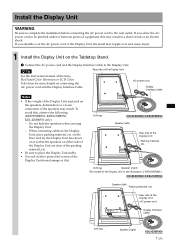
... holes on . Then confirm that the hooks on the rear of the fixtures. Note Do not stumble over the AC power cord or the Display Interface Cable.
... holes on . Then confirm that the hooks on the rear of the fixtures. Note Do not stumble over the AC power cord or the Display Interface Cable.
Instructions for stand (primary manual)
Page 9
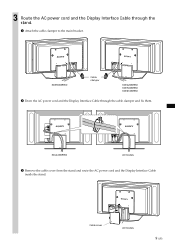
KDL42XBR950 All models 3 Remove the cable cover from the stand and route the AC power cord and the Display Interface Cable inside the stand. Cable cover All models 9 (US) 3 Route the AC power cord and the Display Interface Cable through the cable clamper and fix them. KDE55XBR950 Cable clamper KDE42XBR950 KDE50XBR950 KDE61XBR950 2 Draw the AC power cord and the Display Interface Cable through the stand. 1 Attach the cable clamper to the main bracket.
KDL42XBR950 All models 3 Remove the cable cover from the stand and route the AC power cord and the Display Interface Cable inside the stand. Cable cover All models 9 (US) 3 Route the AC power cord and the Display Interface Cable through the cable clamper and fix them. KDE55XBR950 Cable clamper KDE42XBR950 KDE50XBR950 KDE61XBR950 2 Draw the AC power cord and the Display Interface Cable through the stand. 1 Attach the cable clamper to the main bracket.


