Operating Guide
Page 36
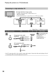
COMPONENT IN AUDIO HDMI i.LINK (for HDV1080i) A B C Type Camcorder Cable A 1 Component video cable (supplied) (Green) Y (Blue) PB/CB (Red) PR/CR : Signal flow, ( ): Reference pages TV Menu Setting (STANDARD SET) [VCR HDV/DV] t [AUTO]...; An A/V connecting cable is (SD image quality). Connect the white and red plugs of the A/ V connecting cable to output audio signals. Playing the picture on a TV (Continued) Connecting to a high definition TV HD (high definition) image quality • An HDV formatted picture is played back as it is (HD image quality). • A DV formatted ...
COMPONENT IN AUDIO HDMI i.LINK (for HDV1080i) A B C Type Camcorder Cable A 1 Component video cable (supplied) (Green) Y (Blue) PB/CB (Red) PR/CR : Signal flow, ( ): Reference pages TV Menu Setting (STANDARD SET) [VCR HDV/DV] t [AUTO]...; An A/V connecting cable is (SD image quality). Connect the white and red plugs of the A/ V connecting cable to output audio signals. Playing the picture on a TV (Continued) Connecting to a high definition TV HD (high definition) image quality • An HDV formatted picture is played back as it is (HD image quality). • A DV formatted ...
Operating Guide
Page 37
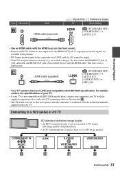
...) cannot be set so that the camcorder is (SD image quality). COMPONENT IN AUDIO i.LINK S VIDEO VIDEO/AUDIO VIDEO/AUDIO D E F G Continued , 37 This may not function correctly (e.g., no sound or image). Connecting to a 16:9 (wide) or 4:3 TV SD (standard definition) image quality • An HDV ...formatted picture is down converted to DV format (SD image quality) and played back. • A DV formatted picture is played back as illustrated in the pictures. • DV format pictures input to be output. •...
...) cannot be set so that the camcorder is (SD image quality). COMPONENT IN AUDIO i.LINK S VIDEO VIDEO/AUDIO VIDEO/AUDIO D E F G Continued , 37 This may not function correctly (e.g., no sound or image). Connecting to a 16:9 (wide) or 4:3 TV SD (standard definition) image quality • An HDV ...formatted picture is down converted to DV format (SD image quality) and played back. • A DV formatted picture is played back as illustrated in the pictures. • DV format pictures input to be output. •...

Operating Guide
Page 38
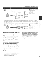
..., set so that it recognizes that the camcorder is also needed to output audio signals. E 4 i.LINK cable (supplied) (STANDARD SET) [VCR HDV/DV] t [AUTO] (57) [i.LINK CONV] t [ON HDV t DV] (60) • The TV needs to the audio input jack of your TV (p. 60). Connect ...the white and red plugs of the A/V connecting cable to be set [ WIDE SELECT] to [4:3] on a 4:3 TV not compatible with your camcorder when recording a picture (p. 58). : Signal flow, ( ): Reference pages Type Camcorder Cable TV Menu Setting D...
..., set so that it recognizes that the camcorder is also needed to output audio signals. E 4 i.LINK cable (supplied) (STANDARD SET) [VCR HDV/DV] t [AUTO] (57) [i.LINK CONV] t [ON HDV t DV] (60) • The TV needs to the audio input jack of your TV (p. 60). Connect ...the white and red plugs of the A/V connecting cable to be set [ WIDE SELECT] to [4:3] on a 4:3 TV not compatible with your camcorder when recording a picture (p. 58). : Signal flow, ( ): Reference pages Type Camcorder Cable TV Menu Setting D...
Operating Guide
Page 39
...device with a cable supplies high quality images and digital audio. • If you connect your camcorder to output images from a jack other than the i.LINK jack, the order of priority of i.LINK. 39 z Tips • The HDMI (High Definition Multimedia Interface) is as ...follows: HDMI t component video t S VIDEO t audio/video. • See page 96 for the details of the output signals is an interface to the input...
...device with a cable supplies high quality images and digital audio. • If you connect your camcorder to output images from a jack other than the i.LINK jack, the order of priority of i.LINK. 39 z Tips • The HDMI (High Definition Multimedia Interface) is as ...follows: HDMI t component video t S VIDEO t audio/video. • See page 96 for the details of the output signals is an interface to the input...

Operating Guide
Page 66
The audio will be unstable or rough at that point. • Set [DISP OUTPUT] to [...devices such as HDRHC5/HC7 and are dubbed as video input1 and video input2). Insert the recorded cassette. If your camcorder for playback. When connecting with the A/V connecting cable with an S VIDEO (optional) Connect with the S VIDEO cable... produces pictures more faithfully. b Notes • When [VCR HDV/DV] is set it to the appropriate input (such as SD (standard definition) images, regardless of the video plug (yellow). Menu setting Recorded Dubbing format format [VCR HDV/ [i.LINK ...
The audio will be unstable or rough at that point. • Set [DISP OUTPUT] to [...devices such as HDRHC5/HC7 and are dubbed as video input1 and video input2). Insert the recorded cassette. If your camcorder for playback. When connecting with the A/V connecting cable with an S VIDEO (optional) Connect with the S VIDEO cable... produces pictures more faithfully. b Notes • When [VCR HDV/DV] is set it to the appropriate input (such as SD (standard definition) images, regardless of the video plug (yellow). Menu setting Recorded Dubbing format format [VCR HDV/ [i.LINK ...

Operating Guide
Page 86
... Down convert the pictures recorded in HDV format to DV format and dub in HD (high definition) image quality (p. 65). You cannot add sound to the recorded tape. • ...on this function is not connected properly. Functions that the A/V connecting cable is connected to the input jack of the connected device (p. 57). • If the device to the recorded tape on... USB devices other device for recording. New sound added to a recorded tape on another camcorder is not heard. • Adjust [ AUDIO MIX] from the [ST1] (original sound) side until the sound is distorted during dubbing...
... Down convert the pictures recorded in HDV format to DV format and dub in HD (high definition) image quality (p. 65). You cannot add sound to the recorded tape. • ...on this function is not connected properly. Functions that the A/V connecting cable is connected to the input jack of the connected device (p. 57). • If the device to the recorded tape on... USB devices other device for recording. New sound added to a recorded tape on another camcorder is not heard. • Adjust [ AUDIO MIX] from the [ST1] (original sound) side until the sound is distorted during dubbing...

Operating Guide
Page 91
...format You need an HDV1080i compatible TV (or monitor) with a component jack and AUDIO/VIDEO input jack. A component video cable and A/V connecting cable are . Additional Information 91 AC-L200/L200B [a] [b] On TV color systems Your camcorder is also needed . System NTSC PAL PAL - Bulgaria, France, Guiana, Iran,..., the U.S.A., Venezuela, etc. Use a commercially available AC plug adaptor [a], if necessary, depending on an NTSC system TV with an AUDIO/VIDEO input jack. Additional Information Using your camcorder abroad Power supply You can easily set the time difference (p. 63).
...format You need an HDV1080i compatible TV (or monitor) with a component jack and AUDIO/VIDEO input jack. A component video cable and A/V connecting cable are . Additional Information 91 AC-L200/L200B [a] [b] On TV color systems Your camcorder is also needed . System NTSC PAL PAL - Bulgaria, France, Guiana, Iran,..., the U.S.A., Venezuela, etc. Use a commercially available AC plug adaptor [a], if necessary, depending on an NTSC system TV with an AUDIO/VIDEO input jack. Additional Information Using your camcorder abroad Power supply You can easily set the time difference (p. 63).

Operating Guide
Page 102
Specifications (Continued) Input/Output connectors Audio/Video output 10-pin connector Video signal: 1 Vp-p, 75 Ω (ohms) Luminance signal: 1 Vp-p, 75 Ω (ohms) Chrominance signal: 0.286 Vp-p, 75 Ω (ohms) Audio signal: 327 mV (at load impedance 47 kΩ (kilohms)), Output impedance...°C to + 40 °C (32 °F to 104 °F) Storage temperature -20 °C to + 60 °C (-4 °F to + 140 °F) Dimensions (approx.) HDR-HC5: 82 × 82 × 134 mm (3 1/4 × 3 1/4 × 5 3/8 in.) (w/h/d) including the projecting parts 82 × 82 × 134 mm (3 1/4 &#...
Specifications (Continued) Input/Output connectors Audio/Video output 10-pin connector Video signal: 1 Vp-p, 75 Ω (ohms) Luminance signal: 1 Vp-p, 75 Ω (ohms) Chrominance signal: 0.286 Vp-p, 75 Ω (ohms) Audio signal: 327 mV (at load impedance 47 kΩ (kilohms)), Output impedance...°C to + 40 °C (32 °F to 104 °F) Storage temperature -20 °C to + 60 °C (-4 °F to + 140 °F) Dimensions (approx.) HDR-HC5: 82 × 82 × 134 mm (3 1/4 × 3 1/4 × 5 3/8 in.) (w/h/d) including the projecting parts 82 × 82 × 134 mm (3 1/4 &#...

Operating Guide
Page 111
... Upper left Indicator SP LP Upper right Indicator +2 +3 Center Meaning Recording format (57) AUDIO MODE* (58) Recording mode* (58) Self-timer recording (48) WIDE SELECT* (58) QUICK REC** (62) Interval photo recording (53) Flash light (47) Meaning HDV input/ DV input (68) HDV output/ DV output (35, 66) i.LINK connection (35, 66, 68...
... Upper left Indicator SP LP Upper right Indicator +2 +3 Center Meaning Recording format (57) AUDIO MODE* (58) Recording mode* (58) Self-timer recording (48) WIDE SELECT* (58) QUICK REC** (62) Interval photo recording (53) Flash light (47) Meaning HDV input/ DV input (68) HDV output/ DV output (35, 66) i.LINK connection (35, 66, 68...


