Operating Instructions
Page 1
Sony Corporation Printed in Korea FWD-50PX3 3-269-308-02(1) Flat Wide Display Monitor JP Operating Instructions GB Mode d'emploi FR Bedienungsanleitung DE Manual de instrucciones ES Istruzioni per l'uso IT CS FWD-50PX3 © 2007 Sony Corporation
Sony Corporation Printed in Korea FWD-50PX3 3-269-308-02(1) Flat Wide Display Monitor JP Operating Instructions GB Mode d'emploi FR Bedienungsanleitung DE Manual de instrucciones ES Istruzioni per l'uso IT CS FWD-50PX3 © 2007 Sony Corporation
Operating Instructions
Page 48
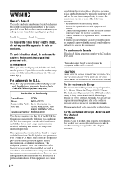
... given in separate service or guarantee documents. If you have any changes or modifications not expressly approved in this manual could void your Sony dealer regarding this product is no guarantee that may cause harmful interference to these numbers whenever you carry the display... rain or moisture. This equipment has been tested and found to comply with Part 15 of Conformity Trade Name: SONY Model: FWD-50PX3 Responsible Party: Sony Electronics Inc. Refer to radio communications. To avoid electrical shock, do not expose this apparatus to operate this device...
... given in separate service or guarantee documents. If you have any changes or modifications not expressly approved in this manual could void your Sony dealer regarding this product is no guarantee that may cause harmful interference to these numbers whenever you carry the display... rain or moisture. This equipment has been tested and found to comply with Part 15 of Conformity Trade Name: SONY Model: FWD-50PX3 Responsible Party: Sony Electronics Inc. Refer to radio communications. To avoid electrical shock, do not expose this apparatus to operate this device...
Operating Instructions
Page 56
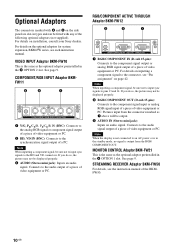
... details on the optional adaptors for system expansion, BKM-FW series, see the instruction manual of a PC. Optional Adaptors The connectors marked with 6 and 8 on the side panel are slot-in types and can be fitted with any of video equipment or PC. COMPONENT/RGB INPUT Adaptor BKMFW11 1 ... Adaptor BKM-FW21 This is the same as the optional adaptor preinstalled in the 8 OPTION 2 slot. For details on installation, consult your Sony dealers. VIDEO INPUT Adaptor BKM-FW10 This is the same as the optional adaptor preinstalled in the 6 OPTION 1 slot. Connects to the synchronization...
... details on the optional adaptors for system expansion, BKM-FW series, see the instruction manual of a PC. Optional Adaptors The connectors marked with 6 and 8 on the side panel are slot-in types and can be fitted with any of video equipment or PC. COMPONENT/RGB INPUT Adaptor BKMFW11 1 ... Adaptor BKM-FW21 This is the same as the optional adaptor preinstalled in the 8 OPTION 2 slot. For details on installation, consult your Sony dealers. VIDEO INPUT Adaptor BKM-FW10 This is the same as the optional adaptor preinstalled in the 6 OPTION 1 slot. Connects to the synchronization...
Operating Instructions
Page 57
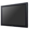
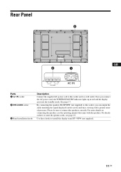
...the speakers correctly. For more details on connecting the speakers, see page 18. For details on the screen and enjoy viewing with the speakers. Rear Panel GB Parts 1 AC IN socket 2 SPEAKER socket 3 Stand installation hooks Description Connect the supplied AC power cord to this socket, you connect the AC... the standby mode. By connecting the speakers SS-SP50FW (not supplied) to this socket and to route the speaker cords, see the operating manual that came with a greater sense of presence. Once you can output the audio matching the signal displayed on how to a wall outlet.
...the speakers correctly. For more details on connecting the speakers, see page 18. For details on the screen and enjoy viewing with the speakers. Rear Panel GB Parts 1 AC IN socket 2 SPEAKER socket 3 Stand installation hooks Description Connect the supplied AC power cord to this socket, you connect the AC... the standby mode. By connecting the speakers SS-SP50FW (not supplied) to this socket and to route the speaker cords, see the operating manual that came with a greater sense of presence. Once you can output the audio matching the signal displayed on how to a wall outlet.
Operating Instructions
Page 59
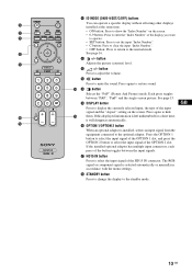
... to select the input signal of the HD15 IN connector. Each press toggles between the input signals. If this displayed information is selected automatically or manually in accordance with the menu settings. See page 16. qj HD15 IN button Press to select the input signal of the button toggles between "P&P", "PinP...
... to select the input signal of the HD15 IN connector. Each press toggles between the input signals. If this displayed information is selected automatically or manually in accordance with the menu settings. See page 16. qj HD15 IN button Press to select the input signal of the button toggles between "P&P", "PinP...
Operating Instructions
Page 63
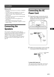
... the AC plug holder and freeing it out by connecting the speakers SS-SP50FW (not supplied). Never pull the cable itself. • See the instruction manual of the equipment to be connected, too. • Insert the plug securely into the AC IN socket. Then, attach the AC plug holder (supplied) ...power cord into the AC IN socket. • Use one of the two AC plug holders (supplied) to route the speaker cords, see the operating manual of the speakers. For more details on how to securely hold the AC plug. A loose connection may cause hum and other noise. • To ...
... the AC plug holder and freeing it out by connecting the speakers SS-SP50FW (not supplied). Never pull the cable itself. • See the instruction manual of the equipment to be connected, too. • Insert the plug securely into the AC IN socket. Then, attach the AC plug holder (supplied) ...power cord into the AC IN socket. • Use one of the two AC plug holders (supplied) to route the speaker cords, see the operating manual of the speakers. For more details on how to securely hold the AC plug. A loose connection may cause hum and other noise. • To ...
Operating Instructions
Page 71
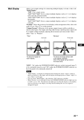
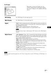
...multiple displays such as 2, 3 or 4 displays both vertically and horizontally. "LED": "On" makes the POWER/STANDBY indicator on the front panel (page 7) to be continually turned off (standby), errors are detected, or the display is in sleep mode including the case of each ...set to "Full 2" for connecting multiple displays to form a video wall. Select either format, suitable picture output will be available without manually adjusting the horizontal and vertical shift. "2×1"/"3×1"/"4×1": Sets to be continually turned on, and "Off" makes the POWER/STANDBY ...
...multiple displays such as 2, 3 or 4 displays both vertically and horizontally. "LED": "On" makes the POWER/STANDBY indicator on the front panel (page 7) to be continually turned off (standby), errors are detected, or the display is in sleep mode including the case of each ...set to "Full 2" for connecting multiple displays to form a video wall. Select either format, suitable picture output will be available without manually adjusting the horizontal and vertical shift. "2×1"/"3×1"/"4×1": Sets to be continually turned on, and "Off" makes the POWER/STANDBY ...
Operating Instructions
Page 73
... surrounding of the picture up and down in the window. Note that "Auto Adjustment" may not work well with certain input signals. In such cases, manually adjust the options below. "H Size": Allows you to choose a correction. Note If there is switched to move the position of the picture. See "Multi Display...
... surrounding of the picture up and down in the window. Note that "Auto Adjustment" may not work well with certain input signals. In such cases, manually adjust the options below. "H Size": Allows you to choose a correction. Note If there is switched to move the position of the picture. See "Multi Display...
Operating Instructions
Page 78
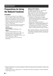
...the network, setting a user name and password is no danger of excessive voltage or voltage surges. • The steps described in this manual are guaranteed only for improvements without notice. • Screens shown by application software may change for use under the following two methods. ...this case the IP address may differ slightly from the illustrations shown in this manual. • For safety, connect the port of this display only to establish the network. mentioned in this manual are registered trademarks of Microsoft Corporation in the United States of America and/ ...
...the network, setting a user name and password is no danger of excessive voltage or voltage surges. • The steps described in this manual are guaranteed only for improvements without notice. • Screens shown by application software may change for use under the following two methods. ...this case the IP address may differ slightly from the illustrations shown in this manual. • For safety, connect the port of this display only to establish the network. mentioned in this manual are registered trademarks of Microsoft Corporation in the United States of America and/ ...
Operating Instructions
Page 79
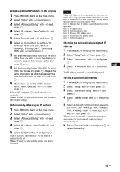
... main menu. 2 Select "Setup" with F/f and press . 3 Select "Advanced Setup" with F/f and press . 4 Select "IP Address Setup" with F/f and press . 5 Select "Manual" with F/f and press . 6 Select an desired item to set from "Auto", "10Mbps Half", "10Mbps Full", "100Mbps Half", or "100Mbps Full" with F/f and press . Assigning a... "Setup" with F/f and press . 3 Select "Information" with F/f and press . 4 Select "IP Address" with F/f, then press . An IP address is automatically set manually. Note When an IP address is displayed. Select "OK" and press . Select "Execute" and press .
... main menu. 2 Select "Setup" with F/f and press . 3 Select "Advanced Setup" with F/f and press . 4 Select "IP Address Setup" with F/f and press . 5 Select "Manual" with F/f and press . 6 Select an desired item to set from "Auto", "10Mbps Half", "10Mbps Full", "100Mbps Half", or "100Mbps Full" with F/f and press . Assigning a... "Setup" with F/f and press . 3 Select "Information" with F/f and press . 4 Select "IP Address" with F/f, then press . An IP address is automatically set manually. Note When an IP address is displayed. Select "OK" and press . Select "Execute" and press .
Operating Instructions
Page 297
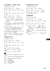
...; MENU 2 用 F/f 选择 "Setup 3 用 F/f 选择 "Advanced Setup 。 4 用 F/f 选择 "IP Address Setup",然后 按。 5 用 F/f 选择 "Manual 6 用 F/f 从"IP Address"、"Subnet Mask"、 "Default Gateway" 、"Primary DNS" 、 "Secondary DNS 7 F/f 0-255 g。 8 0-255),然 6 F/f 9 F/f 选 择 "Execute...
...; MENU 2 用 F/f 选择 "Setup 3 用 F/f 选择 "Advanced Setup 。 4 用 F/f 选择 "IP Address Setup",然后 按。 5 用 F/f 选择 "Manual 6 用 F/f 从"IP Address"、"Subnet Mask"、 "Default Gateway" 、"Primary DNS" 、 "Secondary DNS 7 F/f 0-255 g。 8 0-255),然 6 F/f 9 F/f 选 择 "Execute...
