Operating Instructions
Page 3
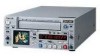
... Trade Name: Model: Responsible Party: Address: Telephone Number: SONY DSR-25 Sony Electronics Inc. 16450 W. However, there is subject to the following measures: • Reorient or relocate the receiving antenna. • Increase the separation between the equipment and receiver. • Connect the equipment into an outlet on , the user is connected. • Consult the dealer or an experienced radio/TV technician for a Class B digital device, pursuant...
... Trade Name: Model: Responsible Party: Address: Telephone Number: SONY DSR-25 Sony Electronics Inc. 16450 W. However, there is subject to the following measures: • Reorient or relocate the receiving antenna. • Increase the separation between the equipment and receiver. • Connect the equipment into an outlet on , the user is connected. • Consult the dealer or an experienced radio/TV technician for a Class B digital device, pursuant...
Operating Instructions
Page 7
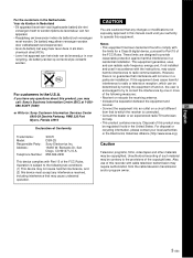
... use time code and user bits. Jog audio function If you can use the Remote Control Unit (DSRM-20, not supplied), audio can be superimposed over the picture being displayed. Chapter 1 Overview DV format compatibility The unit can perform recording and playback in the DV-format (SP mode only). (Recording/playing an image in LP mode is not available.) Digital slow playback The unit has a frame memory function that includes time code and cassette memory data...
... use time code and user bits. Jog audio function If you can use the Remote Control Unit (DSRM-20, not supplied), audio can be superimposed over the picture being displayed. Chapter 1 Overview DV format compatibility The unit can perform recording and playback in the DV-format (SP mode only). (Recording/playing an image in LP mode is not available.) Digital slow playback The unit has a frame memory function that includes time code and cassette memory data...
Operating Instructions
Page 9
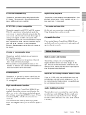
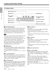
... unit repeats the playback from the beginning to the first index (if there is set COMMANDER on this switch does not work . Location and Function of the tape). CH- 1/2 3/4 MIN MAX 8 RESET button 1 Monitor display section (see page 11 (GB)) 9 CHARACTER DISPLAY switch 4 Display window (see page 16 (GB)) qa EJECT button DSR-25 FIX VAR CH-1 (DUB CH-3) 3 Audio control section NTSC PAL...
... unit repeats the playback from the beginning to the first index (if there is set COMMANDER on this switch does not work . Location and Function of the tape). CH- 1/2 3/4 MIN MAX 8 RESET button 1 Monitor display section (see page 11 (GB)) 9 CHARACTER DISPLAY switch 4 Display window (see page 16 (GB)) qa EJECT button DSR-25 FIX VAR CH-1 (DUB CH-3) 3 Audio control section NTSC PAL...

Operating Instructions
Page 10
... unit is displayed on the Data screen on the LCD monitor on the internal clock and the time code of the FREE RUN setting. After removing the cassette, press this button again to close the compartment. 8 RESET button Press this button. (The menu item settings are maintained.) 10 (GB) Chapter 1 Overview Sounds are displayed, use this button while a cassette is inside the unit, the compartment opens and the cassette is output. Audio mode (32...
... unit is displayed on the Data screen on the LCD monitor on the internal clock and the time code of the FREE RUN setting. After removing the cassette, press this button again to close the compartment. 8 RESET button Press this button. (The menu item settings are maintained.) 10 (GB) Chapter 1 Overview Sounds are displayed, use this button while a cassette is inside the unit, the compartment opens and the cassette is output. Audio mode (32...
Operating Instructions
Page 16
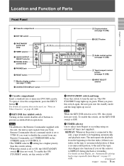
... being played back. 7 Remote control detector 8 Time counter display Displays time data (count value of the counter / time code / user bits), the self-diagnostics code numbers (page 75 (GB)), or the alarm messages ("Err" (page 72 (GB))). Location and Function of Parts Chapter 1 Overview 4 Display window 1 END SEARCH button 2 INDEX button 3 q (cassette) indicator 4 DVCAM indicator NTSC PAL 5 NTSC indicator 6 PAL indicator 0 RESET button 9 COUNTER SELECT selector 8 Time counter display Drop frame indicator 7 Remote control detector 1 END SEARCH button...
... being played back. 7 Remote control detector 8 Time counter display Displays time data (count value of the counter / time code / user bits), the self-diagnostics code numbers (page 75 (GB)), or the alarm messages ("Err" (page 72 (GB))). Location and Function of Parts Chapter 1 Overview 4 Display window 1 END SEARCH button 2 INDEX button 3 q (cassette) indicator 4 DVCAM indicator NTSC PAL 5 NTSC indicator 6 PAL indicator 0 RESET button 9 COUNTER SELECT selector 8 Time counter display Drop frame indicator 7 Remote control detector 1 END SEARCH button...
Operating Instructions
Page 19
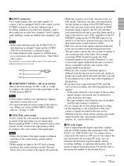
... input via AUDIO jacks, use the S VIDEO connector on conversion cables, refer to PAL, regardless of the TC FORMAT setting on the unit when you use . If you need a device compatible with both NTSC and PAL color system recordings, the following limitations are input to generate the time code in INPUT. they cannot be output. - Notes • In the audio dubbing mode, the AUDIO (CH-1/3) jack functions as channel 3 input and the AUDIO...
... input via AUDIO jacks, use the S VIDEO connector on conversion cables, refer to PAL, regardless of the TC FORMAT setting on the unit when you use . If you need a device compatible with both NTSC and PAL color system recordings, the following limitations are input to generate the time code in INPUT. they cannot be output. - Notes • In the audio dubbing mode, the AUDIO (CH-1/3) jack functions as channel 3 input and the AUDIO...
Operating Instructions
Page 29
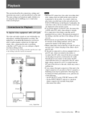
... instruction manual of the editing software. • When connecting a device that of the device to this unit, which may be generated or the image may cause a malfunction. • If you are transmitted to the recorder. Disconnect the cables. DSR-25 (rear panel) Monitor i.LINK cable (DV cable) (not supplied) Notes • With the DV connection, data codes (recording date/ time, camera data) recorded on the source tape are using the unit for input and output. The same settings and operations...
... instruction manual of the editing software. • When connecting a device that of the device to this unit, which may be generated or the image may cause a malfunction. • If you are transmitted to the recorder. Disconnect the cables. DSR-25 (rear panel) Monitor i.LINK cable (DV cable) (not supplied) Notes • With the DV connection, data codes (recording date/ time, camera data) recorded on the source tape are using the unit for input and output. The same settings and operations...

Operating Instructions
Page 30
... the image may be distorted. Recorder Monitor DSR-25 (player) (rear panel) Monitor Audio input Video input S-video input Chapter 2 Playback and Recording Audio cable (Phono jack) (not supplied) 75 Ω coaxial cable (not supplied) S-video cable (not supplied) Connect either an S-video cable or 75 Ω coaxial cable as follows. Use this unit to the output connectors of a recorder or that of the following: • Set EE/PB SEL on the DISPLAY SET menu to PB. • Set the INPUT SELECT selector to video equipment...
... the image may be distorted. Recorder Monitor DSR-25 (player) (rear panel) Monitor Audio input Video input S-video input Chapter 2 Playback and Recording Audio cable (Phono jack) (not supplied) 75 Ω coaxial cable (not supplied) S-video cable (not supplied) Connect either an S-video cable or 75 Ω coaxial cable as follows. Use this unit to the output connectors of a recorder or that of the following: • Set EE/PB SEL on the DISPLAY SET menu to PB. • Set the INPUT SELECT selector to video equipment...

Operating Instructions
Page 31
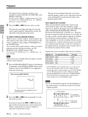
... signals input. 2 Set up the recorder. For details on inserting a cassette, see "CM SET menu" on page 58 (GB). 1 Power on the video monitor, then set the monitor's input switch according to the instruction manual of your computer or the user's manuals of the tape where the recording format has been changed between the DVCAM format and the DV format, the picture and sound may be distorted. 31 Chapter 2 Playback and Recording...
... signals input. 2 Set up the recorder. For details on inserting a cassette, see "CM SET menu" on page 58 (GB). 1 Power on the video monitor, then set the monitor's input switch according to the instruction manual of your computer or the user's manuals of the tape where the recording format has been changed between the DVCAM format and the DV format, the picture and sound may be distorted. 31 Chapter 2 Playback and Recording...

Operating Instructions
Page 32
... data (the shutter speed, SteadyShot, iris, white balance, program AE mode, gain, date and time). Chapter 2 Playback and Recording Playback Playback Functions Displaying information (data codes) recorded on a tape If you record on a tape using DATA CODE on the DISPLAY SET menu, you press the DATA CODE button, the display changes in sequence as follows: no data code t recording date/time t camera data t no data code ..... The data codes consist of the camera data items displayed by this unit. First, set to other than DATA, the data codes are different from those shown on the digital...
... data (the shutter speed, SteadyShot, iris, white balance, program AE mode, gain, date and time). Chapter 2 Playback and Recording Playback Playback Functions Displaying information (data codes) recorded on a tape If you record on a tape using DATA CODE on the DISPLAY SET menu, you press the DATA CODE button, the display changes in sequence as follows: no data code t recording date/time t camera data t no data code ..... The data codes consist of the camera data items displayed by this unit. First, set to other than DATA, the data codes are different from those shown on the digital...
Operating Instructions
Page 34
... 34 (GB) Chapter 2 Playback and Recording or > button repeatedly to locate the original program. For details on the DISPLAY SET menu. For details on the CM SET menu, see "DISPLAY SET menu" on the Remote Control Unit (DSRM-20, not supplied) to the instruction manual of the AUTO INDEX setting. Note Title search is set to perform searches with this unit are four different signal types, one for recording. Each time you want . Please...
... 34 (GB) Chapter 2 Playback and Recording or > button repeatedly to locate the original program. For details on the DISPLAY SET menu. For details on the CM SET menu, see "DISPLAY SET menu" on the Remote Control Unit (DSRM-20, not supplied) to the instruction manual of the AUTO INDEX setting. Note Title search is set to perform searches with this unit are four different signal types, one for recording. Each time you want . Please...

Operating Instructions
Page 37
... editing controller instruction manual. For details on the Remote Commander, the same data codes as a stand-alone recorder. DSR-25 (rear panel) Monitor i.LINK cable (DV cable) (not supplied) DV jack Digital video equipment with hardly any degradation, enabling high-quality recording. As a result, when you want to transmit the contents of the cassette memory, use . • For connection of the editing controller and its peripheral devices, refer to an editing controller via...
... editing controller instruction manual. For details on the Remote Commander, the same data codes as a stand-alone recorder. DSR-25 (rear panel) Monitor i.LINK cable (DV cable) (not supplied) DV jack Digital video equipment with hardly any degradation, enabling high-quality recording. As a result, when you want to transmit the contents of the cassette memory, use . • For connection of the editing controller and its peripheral devices, refer to an editing controller via...

Operating Instructions
Page 38
... beforehand. Chapter 2 Playback and Recording Recording • If the unit is connected to a device equipped with a 6pin DV jack, when you intend to the input connectors of a monitor, a humming noise may be generated or the image may be distorted. Player Monitor DSR-25 (recorder) (rear panel) Monitor S-video output Video output Audio output S-video cable (not supplied) 75 Ω coaxial cable (not supplied) Audio cable (phono jack) (not supplied) : Signal flow Connect either an S-video cable or 75 Ω...
... beforehand. Chapter 2 Playback and Recording Recording • If the unit is connected to a device equipped with a 6pin DV jack, when you intend to the input connectors of a monitor, a humming noise may be generated or the image may be distorted. Player Monitor DSR-25 (recorder) (rear panel) Monitor S-video output Video output Audio output S-video cable (not supplied) 75 Ω coaxial cable (not supplied) Audio cable (phono jack) (not supplied) : Signal flow Connect either an S-video cable or 75 Ω...

Operating Instructions
Page 39
... recording. Audio mode 4-channel mode 2-channel mode Set the menu to FS32K FS48K For details on the AUDIO SET menu, see "AUDIO SET menu" on page 64 (GB). 7 Set the AUDIO INPUT LEVEL selector on the video monitor, then set the monitor's input according to the input signals. 2 Set up the player to record input signals from being changed by an incorrect operation. In this case, set the KEY INH switch to OFF first, then stop or pause the recording. 1 Power...
... recording. Audio mode 4-channel mode 2-channel mode Set the menu to FS32K FS48K For details on the AUDIO SET menu, see "AUDIO SET menu" on page 64 (GB). 7 Set the AUDIO INPUT LEVEL selector on the video monitor, then set the monitor's input according to the input signals. 2 Set up the player to record input signals from being changed by an incorrect operation. In this case, set the KEY INH switch to OFF first, then stop or pause the recording. 1 Power...

Operating Instructions
Page 43
... have the date, time, scene number, and other digits. 7 Press the J/j buttons to that of step 1. The menu display returns to select SET, then press the EXEC button. Note The user bits can set the other information inserted into the time code track. TC ⁄ UB SET TC TC PRESET CM UB PRESET DISP DV IN TC V TC MAKE A TC RUN VTR TC FORMAT ETC RETURN...
... have the date, time, scene number, and other digits. 7 Press the J/j buttons to that of step 1. The menu display returns to select SET, then press the EXEC button. Note The user bits can set the other information inserted into the time code track. TC ⁄ UB SET TC TC PRESET CM UB PRESET DISP DV IN TC V TC MAKE A TC RUN VTR TC FORMAT ETC RETURN...

Operating Instructions
Page 44
... input of a signal begins, the time code of that is set to select SET, then press the EXEC button. To set the time code when the recording starts Set TC MAKE on the front panel is set in DVCAM format Set DV IN TC on the tape. Press the J/j buttons to select the number, then press the EXEC button. 6 Repeat step 5 to set and the menu display returns to be used. To cancel the user...
... input of a signal begins, the time code of that is set to select SET, then press the EXEC button. To set the time code when the recording starts Set TC MAKE on the front panel is set in DVCAM format Set DV IN TC on the tape. Press the J/j buttons to select the number, then press the EXEC button. 6 Repeat step 5 to set and the menu display returns to be used. To cancel the user...

Operating Instructions
Page 45
... is input to the DV jack, the time code generated by the unit during recording in the DVCAM format is that was set in accordance with the loaded tape. If TC MAKE is set to read the frame mode correctly from the tape, the unit will be updated by the internal clock while the unit's power is non-drop frame mode as long as the initial time code...
... is input to the DV jack, the time code generated by the unit during recording in the DVCAM format is that was set in accordance with the loaded tape. If TC MAKE is set to read the frame mode correctly from the tape, the unit will be updated by the internal clock while the unit's power is non-drop frame mode as long as the initial time code...
Operating Instructions
Page 50
.... Moisture condensation has occurred in the DVCAM format. t Set REC MODE to the instruction manual of the recorder (this unit. STOP/ CAUTION No. 00 Warning Message RECORDER: [DV IN] NOT SELECTED 01 i.LINK CABLE: DISCONNECTED 02 i.LINK CABLE: MULTI CONNECTION 03 i.LINK CABLE: BUS RESET 10 PLAYER: RECORDING 11 PLAYER: NO CASSETTE 12 PLAYER: UNCONTROLLABLE 13 PLAYER: UNCONTROLLABLE 14 PLAYER: UNCONTROLLABLE 15 PLAYER: NOT DVCAM PLAYER: 16 UNCONTROLLABLE PLAYER: 18 TAPE INFO. The information on the cassette (see...
.... Moisture condensation has occurred in the DVCAM format. t Set REC MODE to the instruction manual of the recorder (this unit. STOP/ CAUTION No. 00 Warning Message RECORDER: [DV IN] NOT SELECTED 01 i.LINK CABLE: DISCONNECTED 02 i.LINK CABLE: MULTI CONNECTION 03 i.LINK CABLE: BUS RESET 10 PLAYER: RECORDING 11 PLAYER: NO CASSETTE 12 PLAYER: UNCONTROLLABLE 13 PLAYER: UNCONTROLLABLE 14 PLAYER: UNCONTROLLABLE 15 PLAYER: NOT DVCAM PLAYER: 16 UNCONTROLLABLE PLAYER: 18 TAPE INFO. The information on the cassette (see...
Operating Instructions
Page 56
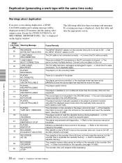
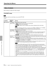
... problem, you may not be used. Note To set the user bits as TC PRESET, UB PRESET, or TC MAKE.) EXTERNAL: Records the time code along with the video and audio signals input via the DV jack in DVCAM format. Operating the Menus Menu Contents Initial settings are recorded as time code. TC/UB SET menu Note All items can set the initial time code value, you cannot change the time code using this item cannot be equal to record internal time code...
... problem, you may not be used. Note To set the user bits as TC PRESET, UB PRESET, or TC MAKE.) EXTERNAL: Records the time code along with the video and audio signals input via the DV jack in DVCAM format. Operating the Menus Menu Contents Initial settings are recorded as time code. TC/UB SET menu Note All items can set the initial time code value, you cannot change the time code using this item cannot be equal to record internal time code...
Operating Instructions
Page 69
... Remote The setting of the power cord from the digital non-linear editing controller does not include a time code. The audio is noisy. • A damaged tape is not available. Check the STOP/CAUTION No. You cannot dub the sound onto channels 1/2. COMMANDER on the OTHERS menu is set to the EE mode or playback mode. • Some items on the OTHERS menu is set COMMANDER using the supplied cleaning cassette. t Control...
... Remote The setting of the power cord from the digital non-linear editing controller does not include a time code. The audio is noisy. • A damaged tape is not available. Check the STOP/CAUTION No. You cannot dub the sound onto channels 1/2. COMMANDER on the OTHERS menu is set to the EE mode or playback mode. • Some items on the OTHERS menu is set COMMANDER using the supplied cleaning cassette. t Control...


