
XL-ES5 | XL-ES50 Operation Manual
Page 2
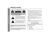
...purchase 0202 Please retain this equipment not expressly approved by one or more of the following measures: ● Reorient or relocate the receiving antenna. ● Increase the separation between the equipment and receiver. ● Connect the equipment into an outlet on the rear of electric...REDUCE THE RISK OF FIRE OR ELECTRIC SHOCK, DO NOT EXPOSE THIS APPLIANCE TO RAIN OR MOISTURE. 0012 Caution - Important Instruction SPECIAL NOTES XL-ES5 XL-ES50 CAUTION: TO REDUCE THE RISK OF ELECTRIC SHOCK, DO NOT REMOVE COVER (OR BACK). NO USER-SERVICEABLE PARTS INSIDE. These limits are ...
...purchase 0202 Please retain this equipment not expressly approved by one or more of the following measures: ● Reorient or relocate the receiving antenna. ● Increase the separation between the equipment and receiver. ● Connect the equipment into an outlet on the rear of electric...REDUCE THE RISK OF FIRE OR ELECTRIC SHOCK, DO NOT EXPOSE THIS APPLIANCE TO RAIN OR MOISTURE. 0012 Caution - Important Instruction SPECIAL NOTES XL-ES5 XL-ES50 CAUTION: TO REDUCE THE RISK OF ELECTRIC SHOCK, DO NOT REMOVE COVER (OR BACK). NO USER-SERVICEABLE PARTS INSIDE. These limits are ...
XL-ES5 | XL-ES50 Operation Manual
Page 4
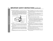
... - NATIONAL ELECTRICAL CODE S2898A ANTENNA DISCHARGE UNIT (NEC SECTION 810-20) GROUNDING CONDUCTORS (NEC SECTION 810-21) GROUND CLAMPS P OWER SERVICE GROUNDING ELECTRODE SYSTEM (NEC ART 250, PART H) 16 Lightning - An outside antenna system, extreme care should not be taken to qualified service personnel. 21 Damage Requiring Service - XL-ES5 XL-ES50 IMPORTANT SAFETY INSTRUCTIONS (continued...
... - NATIONAL ELECTRICAL CODE S2898A ANTENNA DISCHARGE UNIT (NEC SECTION 810-20) GROUNDING CONDUCTORS (NEC SECTION 810-21) GROUND CLAMPS P OWER SERVICE GROUNDING ELECTRODE SYSTEM (NEC ART 250, PART H) 16 Lightning - An outside antenna system, extreme care should not be taken to qualified service personnel. 21 Damage Requiring Service - XL-ES5 XL-ES50 IMPORTANT SAFETY INSTRUCTIONS (continued...
XL-ES5 | XL-ES50 Operation Manual
Page 5
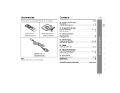
... sleep operation 24 - 26 Enhancing your system 27 „ References Troubleshooting chart 28, 29 Maintenance 29 Specifications 30 CONSUMER LIMITED WARRANTY Back cover General Information XL-ES5 XL-ES50 5 Remote control 1 (RRMCGA003SJSA) FM/AM loop antenna 1 (QANTL0009SJZZ) AC power cord 1 (QACCU0003SJ00) Note: Only the above accessories are included.
... sleep operation 24 - 26 Enhancing your system 27 „ References Troubleshooting chart 28, 29 Maintenance 29 Specifications 30 CONSUMER LIMITED WARRANTY Back cover General Information XL-ES5 XL-ES50 5 Remote control 1 (RRMCGA003SJSA) FM/AM loop antenna 1 (QANTL0009SJZZ) AC power cord 1 (QACCU0003SJ00) Note: Only the above accessories are included.

XL-ES5 | XL-ES50 Operation Manual
Page 8
Speaker Terminals 11 3. Video/Auxiliary (Audio Signal) Input Jacks 27 5. Subwoofer 3. XL-ES5 XL-ES50 Controls and indicators (continued) 1 3 4 2 5 „ Rear panel Reference page 1. Super Tweeter 2. Speaker Wire 3 Note: The speaker grilles are not removable. Woofer 3. FM/AM Loop Antenna Jack 11 4. Cooling Fan 12 General Information 1 2 1 8 „ Front speaker 1. Sub Duct Pipe 2 2. Speaker Wire 4 „ Subwoofer 1. Bass Reflex Duct 3 4. AC Power Input Jack 12 2.
Speaker Terminals 11 3. Video/Auxiliary (Audio Signal) Input Jacks 27 5. Subwoofer 3. XL-ES5 XL-ES50 Controls and indicators (continued) 1 3 4 2 5 „ Rear panel Reference page 1. Super Tweeter 2. Speaker Wire 3 Note: The speaker grilles are not removable. Woofer 3. FM/AM Loop Antenna Jack 11 4. Cooling Fan 12 General Information 1 2 1 8 „ Front speaker 1. Sub Duct Pipe 2 2. Speaker Wire 4 „ Subwoofer 1. Bass Reflex Duct 3 4. AC Power Input Jack 12 2.

XL-ES5 | XL-ES50 Operation Manual
Page 10
Subwoofer FM/AM loop antenna connection (see page 11) FM antenna Front speaker (right) AM loop antenna Front speaker (left) Preparation for Use Speaker connection (see page 11) 10 AC outlet (AC 120 V, 60 Hz) Connecting the AC power cord (see page 12) XL-ES5 XL-ES50 System connections Make sure to unplug the AC power cord before any connections.
Subwoofer FM/AM loop antenna connection (see page 11) FM antenna Front speaker (right) AM loop antenna Front speaker (left) Preparation for Use Speaker connection (see page 11) 10 AC outlet (AC 120 V, 60 Hz) Connecting the AC power cord (see page 12) XL-ES5 XL-ES50 System connections Make sure to unplug the AC power cord before any connections.

XL-ES5 | XL-ES50 Operation Manual
Page 11
.../AM loop antenna to the plus (+) terminal. Place the AM loop antenna on the stereo system or near the AC power cord may be placed in the bass reflex ducts. The right speaker is the one on the speakers. z Do not mistake the right and the left ) XL-ES5 XL-ES50 Preparation for ...Use Notes: z Placing the antenna on a shelf, or attach it to a stand or a wall. „ Speaker connection Connect the black wire to the minus (-) terminal...
.../AM loop antenna to the plus (+) terminal. Place the AM loop antenna on the stereo system or near the AC power cord may be placed in the bass reflex ducts. The right speaker is the one on the speakers. z Do not mistake the right and the left ) XL-ES5 XL-ES50 Preparation for ...Use Notes: z Placing the antenna on a shelf, or attach it to a stand or a wall. „ Speaker connection Connect the black wire to the minus (-) terminal...
XL-ES5 | XL-ES50 Operation Manual
Page 28
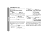
References XL-ES5 XL-ES50 Troubleshooting chart Many potential problems can cause the unit to malfunction. the ...(CD pickup, etc.) or on the transmitter on the transmitter with a soft cloth before calling your authorized SHARP dealer or service center. „ General Symptom Possible cause z The clock is wrong with no disc in...the batteries dead? If something is not set to the z Did a power failure occur? z Is the FM antenna or AM loop antenna placed properly? z If the unit still malfunctions, reset it 's located nearby. „ Condensation Sudden temperature changes...
References XL-ES5 XL-ES50 Troubleshooting chart Many potential problems can cause the unit to malfunction. the ...(CD pickup, etc.) or on the transmitter on the transmitter with a soft cloth before calling your authorized SHARP dealer or service center. „ General Symptom Possible cause z The clock is wrong with no disc in...the batteries dead? If something is not set to the z Did a power failure occur? z Is the FM antenna or AM loop antenna placed properly? z If the unit still malfunctions, reset it 's located nearby. „ Condensation Sudden temperature changes...


