
Service Manual
Page 1
MODEL XL-3700 XL-3700 Compact Audio System consisting of XL-3600 (main unit) and CP-XL3600U (speaker system). ONLY) SHARP CORPORATION - 1 - CONTENTS Page IMPORTANT SERVICE NOTES (FOR U.S.A. XL-3600 XL-3700/C SERVICE MANUAL No. ONLY) ...2 SPECIFICATIONS ...3 NAMES OF PARTS ...4 DISASSEMBLY ...6 REMOVING AND REINSTALLING THE MAIN PARTS ...8 ADJUSTMENT ...9 TEST MODE ...10 NOTES ON SCHEMATIC DIAGRAM ...17 TYPES OF TRANSISTOR AND LED ...17 WAVEFORMS OF CD CIRCUIT ...18 BLOCK DIAGRAM ...19 SCHEMATIC DIAGRAM ...22 WIRING SIDE OF P.W.BOARD ...30 TROUBLESHOOTING ...34...
MODEL XL-3700 XL-3700 Compact Audio System consisting of XL-3600 (main unit) and CP-XL3600U (speaker system). ONLY) SHARP CORPORATION - 1 - CONTENTS Page IMPORTANT SERVICE NOTES (FOR U.S.A. XL-3600 XL-3700/C SERVICE MANUAL No. ONLY) ...2 SPECIFICATIONS ...3 NAMES OF PARTS ...4 DISASSEMBLY ...6 REMOVING AND REINSTALLING THE MAIN PARTS ...8 ADJUSTMENT ...9 TEST MODE ...10 NOTES ON SCHEMATIC DIAGRAM ...17 TYPES OF TRANSISTOR AND LED ...17 WAVEFORMS OF CD CIRCUIT ...18 BLOCK DIAGRAM ...19 SCHEMATIC DIAGRAM ...22 WIRING SIDE OF P.W.BOARD ...30 TROUBLESHOOTING ...34...
Service Manual
Page 2
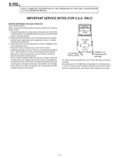
... outlet. * Using two clip leads, connect a 1.5k ohm, 10 watt resistor paralleled by a 0.15µF capacitor in the audio product. 2. AC.) or more is not lodged between the chassis and other metal parts in series with all protective devices such as conduit or electrical ground connected to 0.2 milliamp. IMPORTANT SERVICE NOTES (FOR U.S.A. XL-3600 XL-3700/C FOR A COMPLETE DESCRIPTION OF THE OPERATION OF...
... outlet. * Using two clip leads, connect a 1.5k ohm, 10 watt resistor paralleled by a 0.15µF capacitor in the audio product. 2. AC.) or more is not lodged between the chassis and other metal parts in series with all protective devices such as conduit or electrical ground connected to 0.2 milliamp. IMPORTANT SERVICE NOTES (FOR U.S.A. XL-3600 XL-3700/C FOR A COMPLETE DESCRIPTION OF THE OPERATION OF...
Service Manual
Page 3
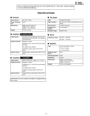
... Frequency response Dynamic range Compact disc player Non-contact, 3-beam semiconductor laser pickup 1-bit D/A converter 20 - 20,000 Hz 90 dB (1 kHz) s Amplifier XL-3600/XL-3700 Output power Output terminals Input terminals 20 watts minimum RMS per channel into 6 ohms from 100 Hz to 20 kHz, 10% total harmonic distortion Speakers: 6 ohms Headphones: 16 - 50 ohms (recommended: 32 ohms) CD digital output (optical) Subwoofer (Audio signal): 500 mV/47 k ohms Video/Auxiliary (audio signal): 500 mV/47 k ohms s Amplifier Output power Output terminals Input terminals XL...
... Frequency response Dynamic range Compact disc player Non-contact, 3-beam semiconductor laser pickup 1-bit D/A converter 20 - 20,000 Hz 90 dB (1 kHz) s Amplifier XL-3600/XL-3700 Output power Output terminals Input terminals 20 watts minimum RMS per channel into 6 ohms from 100 Hz to 20 kHz, 10% total harmonic distortion Speakers: 6 ohms Headphones: 16 - 50 ohms (recommended: 32 ohms) CD digital output (optical) Subwoofer (Audio signal): 500 mV/47 k ohms Video/Auxiliary (audio signal): 500 mV/47 k ohms s Amplifier Output power Output terminals Input terminals XL...

Service Manual
Page 4
... Play or Pause, Tuning Up Button 5 8 9 s Display 1. Surround Indicator 1 2 3 4 5 6 1 2 3 s Rear panel 1. Speaker Terminals 10. CD Open/Close Button 3. FM Stereo Mode Indicator 6. Sleep Indicator 3. Antenna Earth Terminal 6. FM 75 Ohms Antenna Jack 7. After 15 - 30 minutes, turn the TV on the TV screen. - 4 - Bass Reflex Duct 4. XL-3600 XL-3700/C 8 1 9 10 2 5 3 6 7 4 1 23 4 6 7 NAMES OF PARTS s Front panel 11 1. CD Stop, Tuning Down Button 9. FM Stereo Receiving Indicator 9. AC Power Input Jack s Speaker system 7 1. CD Digital Output Jack...
... Play or Pause, Tuning Up Button 5 8 9 s Display 1. Surround Indicator 1 2 3 4 5 6 1 2 3 s Rear panel 1. Speaker Terminals 10. CD Open/Close Button 3. FM Stereo Mode Indicator 6. Sleep Indicator 3. Antenna Earth Terminal 6. FM 75 Ohms Antenna Jack 7. After 15 - 30 minutes, turn the TV on the TV screen. - 4 - Bass Reflex Duct 4. XL-3600 XL-3700/C 8 1 9 10 2 5 3 6 7 4 1 23 4 6 7 NAMES OF PARTS s Front panel 11 1. CD Stop, Tuning Down Button 9. FM Stereo Receiving Indicator 9. AC Power Input Jack s Speaker system 7 1. CD Digital Output Jack...

Service Manual
Page 5
... Down Buttons 27. Treble Up and Down Buttons Buttons with " " mark in the illustration can be operated on the remote control only. CD Button 21 4. XL-3600 XL-3700/C - 5 - Tuner Button 5. CD Open/Close Button 9 17. Tuner Preset Down Button 26. Timer Button 6. CD Track Down Button 10 26 27 19. CD Fast Reverse, Tuning Down Button 20. CD Track Up Button 22. Remote Control Transmitter 2 12 2. Memory Button 6 7 16 20 8. Surround Button 23 10. CD Play Button 21...
... Down Buttons 27. Treble Up and Down Buttons Buttons with " " mark in the illustration can be operated on the remote control only. CD Button 21 4. XL-3600 XL-3700/C - 5 - Tuner Button 5. CD Open/Close Button 9 17. Tuner Preset Down Button 26. Timer Button 6. CD Track Down Button 10 26 27 19. CD Fast Reverse, Tuning Down Button 20. CD Track Up Button 22. Remote Control Transmitter 2 12 2. Memory Button 6 7 16 20 8. Surround Button 23 10. CD Play Button 21...
Service Manual
Page 9
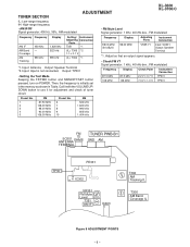
... in Table. Call it with the VOLUME UP/ DOWN button to use it for adjustment and check of tuner circuit. Then, the frequency is not connected, Output: TP301 • Setting the Test Mode Keeping the FF/FWD button and MEMORY/SET button pressed, turn on POWER. FM Preset No. Input: Antenna, Output: Speaker Terminal *2. Frequency Display 98.00 MHz (30 dBµV) 98.00 MHz Adjusting Parts VR351*1 Instrument Connection Input: SO301 Output: Speaker Terminal *1. AM 1 87.50 MHz...
... in Table. Call it with the VOLUME UP/ DOWN button to use it for adjustment and check of tuner circuit. Then, the frequency is not connected, Output: TP301 • Setting the Test Mode Keeping the FF/FWD button and MEMORY/SET button pressed, turn on POWER. FM Preset No. Input: Antenna, Output: Speaker Terminal *2. Frequency Display 98.00 MHz (30 dBµV) 98.00 MHz Adjusting Parts VR351*1 Instrument Connection Input: SO301 Output: Speaker Terminal *1. AM 1 87.50 MHz...
Service Manual
Page 10
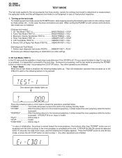
... to proceed to the ordinary standby mode. Press the POWER button to end the test mode, or press the CD STOP button to return to the step 1 by pressing the CD STOP button. Tuner Test Mode (TEST 2 BASS/TREBLE + VOL+ 3. Electronic Volume Test Mode (TEST 3 BASS/TREBLE + VOL- 4. MEMORY/SET + VOL+ [Self-diagnosis Test Mode] 1. Button input diagnosis test mode (TEST6)........MEMORY/SET + PLAY Processes are not obtained. [Ordinary test mode] 1. CD Test Mode (TEST 1) In the CD test mode the operation of initialization, the pickup is...
... to proceed to the ordinary standby mode. Press the POWER button to end the test mode, or press the CD STOP button to return to the step 1 by pressing the CD STOP button. Tuner Test Mode (TEST 2 BASS/TREBLE + VOL+ 3. Electronic Volume Test Mode (TEST 3 BASS/TREBLE + VOL- 4. MEMORY/SET + VOL+ [Self-diagnosis Test Mode] 1. Button input diagnosis test mode (TEST6)........MEMORY/SET + PLAY Processes are not obtained. [Ordinary test mode] 1. CD Test Mode (TEST 1) In the CD test mode the operation of initialization, the pickup is...

Service Manual
Page 11
... standby mode. Step 2 Mode Press the "CD PLAY" button in this button is on the laser. "POWER Test mode and power turned off to shift to obtain the operations specified below. Any other operations are not performed in this state to obtain the operations specified below . If PICKUP IN is on , input is pressed. Press the following buttons in this mode to the ordinary standby mode. Press the following buttons...
... standby mode. Step 2 Mode Press the "CD PLAY" button in this button is on the laser. "POWER Test mode and power turned off to shift to obtain the operations specified below. Any other operations are not performed in this state to obtain the operations specified below . If PICKUP IN is on , input is pressed. Press the following buttons in this mode to the ordinary standby mode. Press the following buttons...

Service Manual
Page 12
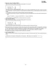
... the outer periphery while this test mode. 6. During the display, music signal is pressed. "PLAY Invalid "STOP Return to step 1 "FUNCTION Shift to step 5 "MEMORY Shift to step 7 Press FF/PRESET UP or REW/PRESET DOWN button to the ordinary standby mode. Even if playback reaches the outermost periphery of errors for 1 frame (1 sub-code block in this state to monitor BUS2 (QDRE) during "H". Other cautions...
... the outer periphery while this test mode. 6. During the display, music signal is pressed. "PLAY Invalid "STOP Return to step 1 "FUNCTION Shift to step 5 "MEMORY Shift to step 7 Press FF/PRESET UP or REW/PRESET DOWN button to the ordinary standby mode. Even if playback reaches the outermost periphery of errors for 1 frame (1 sub-code block in this state to monitor BUS2 (QDRE) during "H". Other cautions...

Service Manual
Page 13
... following buttons in hexadecimal numbers. "PLAY Invalid "STOP Return to step 1 "FUNCTION Shift to step 6 "MEMORY Shift to step 5 *If the focus is shifted to step 1. - 13 - XL-3600 XL-3700/C 7. Then data read by read command SRC2 (2) are displayed in hexadecimal numbers. Then data read by read command SRC2 (2) are displayed in hexadecimal numbers. After waiting 2 seconds, operation is not received, the...
... following buttons in hexadecimal numbers. "PLAY Invalid "STOP Return to step 1 "FUNCTION Shift to step 6 "MEMORY Shift to step 5 *If the focus is shifted to step 1. - 13 - XL-3600 XL-3700/C 7. Then data read by read command SRC2 (2) are displayed in hexadecimal numbers. Then data read by read command SRC2 (2) are displayed in hexadecimal numbers. After waiting 2 seconds, operation is not received, the...

Service Manual
Page 14
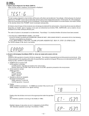
Details of TUNER function. FUNCTION switching is obtained with the ordinary operations of tuner test mode Press the "REW/PRESET DOWN" and "CD PLAY" buttons in the TEST2 mode to initialize memory. When the tuner test mode is obtained, the following display lights for judging memory error at initial setting and to restore the initial state. Turn off POWER to be checked for one second. • The TUNER TEST2 mode is invalid. CH 16...
Details of TUNER function. FUNCTION switching is obtained with the ordinary operations of tuner test mode Press the "REW/PRESET DOWN" and "CD PLAY" buttons in the TEST2 mode to initialize memory. When the tuner test mode is obtained, the following display lights for judging memory error at initial setting and to restore the initial state. Turn off POWER to be checked for one second. • The TUNER TEST2 mode is invalid. CH 16...
Service Manual
Page 15
... as one second. Lighting of ordinary timer operation. 6. Electronic volume Test Mode (TEST 3) When this mode, volume is -14 dB (STEP28), BASS/TREBLE is shifted to CD, respectively. Then pressing the "PLAY" button switches display as that of fade-out, the power is turned off (after WAIT 1 sec), and the mode is set to 0 (0 dB) and SURROUND mode to OFF, and start-up function to the standby. The button operations in accordance with the...
... as one second. Lighting of ordinary timer operation. 6. Electronic volume Test Mode (TEST 3) When this mode, volume is -14 dB (STEP28), BASS/TREBLE is shifted to CD, respectively. Then pressing the "PLAY" button switches display as that of fade-out, the power is turned off (after WAIT 1 sec), and the mode is set to 0 (0 dB) and SURROUND mode to OFF, and start-up function to the standby. The button operations in accordance with the...
Service Manual
Page 16
... the standby mode if the "POWER" button is displayed. PLAY, BASS/TREBLE, FUNCTION, VOLUME UP/DOWN, MEMORY/SET, REW, FF, STOP, CD-OPEN/CLOSE The OK/NG display of repeated times and time period are available at the initial setting by MODEL port. Position other than CLOSE: After the lid moves to CLOSE, operation proceeds to the next process. b. if the count is over 59999, display is displayed. Button input diagnosis Test Mode (TEST...
... the standby mode if the "POWER" button is displayed. PLAY, BASS/TREBLE, FUNCTION, VOLUME UP/DOWN, MEMORY/SET, REW, FF, STOP, CD-OPEN/CLOSE The OK/NG display of repeated times and time period are available at the initial setting by MODEL port. Position other than CLOSE: After the lid moves to CLOSE, operation proceeds to the next process. b. if the count is over 59999, display is displayed. Button input diagnosis Test Mode (TEST...
Service Manual
Page 17
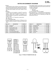
... used : the symbol K means 1000 ohm and the symbol M means 1000 kohm and the resistor without such a symbol is stopped. • Parts marked with specified ones for maintaining the safety and performance of the set . In the tuner section, ( ) : AM mode : FM stereo mode 2. NO SW719 SW720 SW725 SW726 SW727 SW728 SW802 DESCRIPTION VOLUME DOWN VOLUME UP BASS/TREBLE MEMORY/SET CLEAR FUNCTION CD...
... used : the symbol K means 1000 ohm and the symbol M means 1000 kohm and the resistor without such a symbol is stopped. • Parts marked with specified ones for maintaining the safety and performance of the set . In the tuner section, ( ) : AM mode : FM stereo mode 2. NO SW719 SW720 SW725 SW726 SW727 SW728 SW802 DESCRIPTION VOLUME DOWN VOLUME UP BASS/TREBLE MEMORY/SET CLEAR FUNCTION CD...

Service Manual
Page 26
XL-3600 XL-3700/C DISPLAY PWB-A2 A +B +B LCD701 FL DISPLAY 1 2 3 4 5 6 7 8 9 10 11 12 13 14 15 16 17 18 19 20 21 B SW727 SW720 CLEAR VOLUME UP R706 1.5K VOLUME DOWN SW719 R716 10K MEMORY/ SET SW726 CD PLAY/PAUSE/ TUNING...TUNING DOWN SW713 R718 3.9K 100 99 98 97 96 95 94 93 92 91 90 89 88 87 86 85 84 BASS/TREBLE FF>REW SW711 R720 3.9K 3 COM1 C FUNCTION PRESET...DRIVER SW710...MODEL R735 1K 20 CLID_PRO 21 FAN_DET R736 1K 22 R725 10K R721 10K 23 VSM +B 24 VREF+ 25 DI REMOCON SYS_STOP POWER RESET... 3.3/50 R7A5 10K Q702 R7B0 10K REMOTE SENSOR RX701 R7A3 100 1K 1K 2...
XL-3600 XL-3700/C DISPLAY PWB-A2 A +B +B LCD701 FL DISPLAY 1 2 3 4 5 6 7 8 9 10 11 12 13 14 15 16 17 18 19 20 21 B SW727 SW720 CLEAR VOLUME UP R706 1.5K VOLUME DOWN SW719 R716 10K MEMORY/ SET SW726 CD PLAY/PAUSE/ TUNING...TUNING DOWN SW713 R718 3.9K 100 99 98 97 96 95 94 93 92 91 90 89 88 87 86 85 84 BASS/TREBLE FF>REW SW711 R720 3.9K 3 COM1 C FUNCTION PRESET...DRIVER SW710...MODEL R735 1K 20 CLID_PRO 21 FAN_DET R736 1K 22 R725 10K R721 10K 23 VSM +B 24 VREF+ 25 DI REMOCON SYS_STOP POWER RESET... 3.3/50 R7A5 10K Q702 R7B0 10K REMOTE SENSOR RX701 R7A3 100 1K 1K 2...

Service Manual
Page 35
... procedure in CD TEST MODE "STEP 2"? Check the procedure "NO SOUND" Does the LCD track number and time indicator work properly ? Does the laser come on . Yes Check the procedure in the FF mode? Yes Does playback continue for 30 seconds after the start playback when PLAY key is normal, and set the CD TEST MODE (STEP 1). Turn the power off and then...
... procedure in CD TEST MODE "STEP 2"? Check the procedure "NO SOUND" Does the LCD track number and time indicator work properly ? Does the laser come on . Yes Check the procedure in the FF mode? Yes Does playback continue for 30 seconds after the start playback when PLAY key is normal, and set the CD TEST MODE (STEP 1). Turn the power off and then...

Service Manual
Page 40
... control. 2 CE Chip enable pin. Each analog switch is (open or connected to the VSS potential. 5 LOUT Volume + equalizer output pin. 6 LBASS2 Bass-band filter comprising capacitor and resistor connection pin. 7 LBASS1 Bass-band filter comprising capacitor and resistor connection pin. 8 LTRE Capacitor connection pin comprising treble band filter. 9 LIN Volume + equalizer input pin. 10 LSEL0 Input selector output pin. 11 L4 Input signal pin. 12* L3 Input signal pin. 13 L2 Input signal...
... control. 2 CE Chip enable pin. Each analog switch is (open or connected to the VSS potential. 5 LOUT Volume + equalizer output pin. 6 LBASS2 Bass-band filter comprising capacitor and resistor connection pin. 7 LBASS1 Bass-band filter comprising capacitor and resistor connection pin. 8 LTRE Capacitor connection pin comprising treble band filter. 9 LIN Volume + equalizer input pin. 10 LSEL0 Input selector output pin. 11 L4 Input signal pin. 12* L3 Input signal pin. 13 L2 Input signal...

Service Manual
Page 43
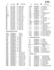
... PROTECTION CONTRE UN INCENDIE, REMPLACER SEULEMENT PAR UN FUSIBLE DE TYPE F651,F652 4.0A, 125V/ F653 1.6A, 125V. DESCRIPTION For location of SHARP Parts Distributor, Please call Toll-Free; 1-800-BE-SHARP MARK: SPARE PARTS-DELIVERY SECTION Explanation of the set . PARTS GUIDE XL-3600 XL-3700/C COMPACT AUDIO SYSTEM MODEL XL-3600 XL-3600 Compact Audio System consisting of XL-3700 (main unit) and CP-XL3700U (speaker system). MODEL XL-3700 XL-3700 Compact Audio System consisting of XL...
... PROTECTION CONTRE UN INCENDIE, REMPLACER SEULEMENT PAR UN FUSIBLE DE TYPE F651,F652 4.0A, 125V/ F653 1.6A, 125V. DESCRIPTION For location of SHARP Parts Distributor, Please call Toll-Free; 1-800-BE-SHARP MARK: SPARE PARTS-DELIVERY SECTION Explanation of the set . PARTS GUIDE XL-3600 XL-3700/C COMPACT AUDIO SYSTEM MODEL XL-3600 XL-3600 Compact Audio System consisting of XL-3700 (main unit) and CP-XL3700U (speaker system). MODEL XL-3700 XL-3700 Compact Audio System consisting of XL...
Service Manual
Page 47
... Remote Sensor AF Terminal,Antenna AG Socket,Video/AUX Input,Sub Woofer Out AF Terminal,Speaker AD Socket AC Input AQ Woofer AH Tweeter AE Switch,Push Type [Pickup In] AD Switch,Key Type [Power] AD Switch,Key Type [CD Lid Open/Close] AD Switch,Key Type [REW/Preset Down] AD Switch,Key Type [FF/Preset Up] AD Switch,Key Type [CD Stop/Tuning Down] AD Switch,Key Type [CD Play/Pause/Tuning...
... Remote Sensor AF Terminal,Antenna AG Socket,Video/AUX Input,Sub Woofer Out AF Terminal,Speaker AD Socket AC Input AQ Woofer AH Tweeter AE Switch,Push Type [Pickup In] AD Switch,Key Type [Power] AD Switch,Key Type [CD Lid Open/Close] AD Switch,Key Type [REW/Preset Down] AD Switch,Key Type [FF/Preset Up] AD Switch,Key Type [CD Stop/Tuning Down] AD Switch,Key Type [CD Play/Pause/Tuning...
Service Manual
Page 48
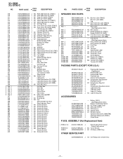
... SP603,604 GBOXS6002SJSA J GBOXS6002SJSB J GLEGP0003SJSA J GWAKP1019SJ01 J GWAKP1019SJ02 J ---- PART CODE PRICE RANK DESCRIPTION NO. Battery (UM-4) (Not Replacement Item) GCABB1064SJSB J Battery Lid,Remote Control 1 QACCU0003SJ00 J AH AC Power Supply Cord QANTL0001SJZZ J AK AM Loop Antenna QANTW0002SJZZ J AH FM Antenna QCNWH0005SJ01 J AF Speaker Wire RRMCG0037SJSA J AT Remote Control TINSE0091SJZZ J Operation Manual [XL-3600/3700] TINSK0032SJZZ J Operation Manual [XL-3700C] TINSZ0139SJZZ J Quick Guide P.W.B. HDECQ0072SJSA J HDECQ0072SJSB J PDUC-0004SJZZ J PSPAG0004SJZZ...
... SP603,604 GBOXS6002SJSA J GBOXS6002SJSB J GLEGP0003SJSA J GWAKP1019SJ01 J GWAKP1019SJ02 J ---- PART CODE PRICE RANK DESCRIPTION NO. Battery (UM-4) (Not Replacement Item) GCABB1064SJSB J Battery Lid,Remote Control 1 QACCU0003SJ00 J AH AC Power Supply Cord QANTL0001SJZZ J AK AM Loop Antenna QANTW0002SJZZ J AH FM Antenna QCNWH0005SJ01 J AF Speaker Wire RRMCG0037SJSA J AT Remote Control TINSE0091SJZZ J Operation Manual [XL-3600/3700] TINSK0032SJZZ J Operation Manual [XL-3700C] TINSZ0139SJZZ J Quick Guide P.W.B. HDECQ0072SJSA J HDECQ0072SJSB J PDUC-0004SJZZ J PSPAG0004SJZZ...


