Service Manual
Page 5
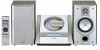
...( or ) button to adjust the hour and then press the MEMORY button. Note: The time will appear. (AM 12:00 - Setting the clock OPERATION MANUAL XL-1700/1700C 3 Within 1 minute, press the PRESET ( or ) button to select 12-hour or 24-hour display and then press the MEMORY... button. The clock starts from the AC INPUT jack on the unit. To readjust the clock: Perform "Setting the clock" from the beginning. To change ...
...( or ) button to adjust the hour and then press the MEMORY button. Note: The time will appear. (AM 12:00 - Setting the clock OPERATION MANUAL XL-1700/1700C 3 Within 1 minute, press the PRESET ( or ) button to select 12-hour or 24-hour display and then press the MEMORY... button. The clock starts from the AC INPUT jack on the unit. To readjust the clock: Perform "Setting the clock" from the beginning. To change ...

Service Manual
Page 41
To be set to be open ) terminal which is activated. Volume + ...to the outside. - 41 - Volume + equalizer input pin. Bass-band filter comprising capacitor and resistor connection pin. Input signal pin. XL-1700/1700C FUNCTION TABLE OF IC IC401 VHiLC75342M-1: Function/Volume Equalizer (LC75342M) Pin No. 1 2 3 4 5 6 7 8 9 10... to VSS. 0.5 x VDD voltage generation block for analog ground. Input signal pin. Serial data and clock input pin for control. Bass-band filter comprising capacitor and resistor connection pin. Input signal pin. Chip ...
To be set to be open ) terminal which is activated. Volume + ...to the outside. - 41 - Volume + equalizer input pin. Bass-band filter comprising capacitor and resistor connection pin. Input signal pin. XL-1700/1700C FUNCTION TABLE OF IC IC401 VHiLC75342M-1: Function/Volume Equalizer (LC75342M) Pin No. 1 2 3 4 5 6 7 8 9 10... to VSS. 0.5 x VDD voltage generation block for analog ground. Input signal pin. Serial data and clock input pin for control. Bass-band filter comprising capacitor and resistor connection pin. Input signal pin. Chip ...


