Service Manual
Page 2
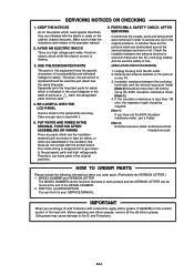
...parts and high voltage parts. Especially as a tube or tape for safety which are indicated with the printed board. BE CAREFUL WITH THE LCD PANEL Avoid a shock to the important parts for safety, or which is designed not to get closer to the IC and Transistor). Therefore...electric shock while the electric current is less than 1M ohm by using the 500V insulation resistance meter [Note 1]. 4. Remove the antenna terminal on TV and turn on the cabinet, chassis and parts. If the insulation resistance is flowing. 3. IMPORTANT When you order parts. (Particularly the VERSION LETTER...
...parts and high voltage parts. Especially as a tube or tape for safety which are indicated with the printed board. BE CAREFUL WITH THE LCD PANEL Avoid a shock to the important parts for safety, or which is designed not to get closer to the IC and Transistor). Therefore...electric shock while the electric current is less than 1M ohm by using the 500V insulation resistance meter [Note 1]. 4. Remove the antenna terminal on TV and turn on the cabinet, chassis and parts. If the insulation resistance is flowing. 3. IMPORTANT When you order parts. (Particularly the VERSION LETTER...
Service Manual
Page 4
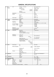
GENERAL SPECIFICATIONS G-1 TV System G-2 Tuning System G-3 Signal LCD LCD Size / Visual Size LCD Type Number of Pixels View Range Left/Right Up/Down Bright Dot Zero Bright Dot Ratio Color System Speaker Position Size Impedance Sound Output...System Analog Digital Tuner and System Receive CH Destination CH Coverage Intermediate Digital Frequency Analog Picture(FP) Sound(FS) FP-FS Preset CH Stereo/Dual TV Sound Tuner Sound Muting Video Signal Input Level Output Level S/N Ratio (Weighted) Horizontal Resolution at DVD Mode RGB Signal Output Level Audio Signal ...
GENERAL SPECIFICATIONS G-1 TV System G-2 Tuning System G-3 Signal LCD LCD Size / Visual Size LCD Type Number of Pixels View Range Left/Right Up/Down Bright Dot Zero Bright Dot Ratio Color System Speaker Position Size Impedance Sound Output...System Analog Digital Tuner and System Receive CH Destination CH Coverage Intermediate Digital Frequency Analog Picture(FP) Sound(FS) FP-FS Preset CH Stereo/Dual TV Sound Tuner Sound Muting Video Signal Input Level Output Level S/N Ratio (Weighted) Horizontal Resolution at DVD Mode RGB Signal Output Level Audio Signal ...
Service Manual
Page 6
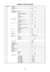
... GENERAL SPECIFICATIONS Auto Shut Off Auto Search Power On Memory Comb Filter Game Position Auto Setup(Language/CH Program) Picture Setting(TV) AV Mode(Picture Preference) Brightness , Contrast , Color Tint Sharpness Color Temperature DNR Cable Clear Picture Setting(PC) HOR Position , VER Position Phase, Clock Red, Green, Blue Auto Adjust Audio MTS...
... GENERAL SPECIFICATIONS Auto Shut Off Auto Search Power On Memory Comb Filter Game Position Auto Setup(Language/CH Program) Picture Setting(TV) AV Mode(Picture Preference) Brightness , Contrast , Color Tint Sharpness Color Temperature DNR Cable Clear Picture Setting(PC) HOR Position , VER Position Phase, Clock Red, Green, Blue Auto Adjust Audio MTS...
Service Manual
Page 13
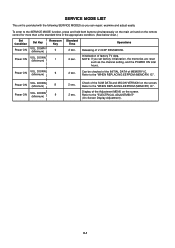
... remote control for more than a the standard time in the appropriate condition. (See below chart.) Set Condition Power ON Set Key VOL. Releasing of factory TV data. C-1 DOWN (Minimum) 8 Power ON VOL. Refer to the SERVICE MODE function, press and hold both buttons simultaneously on the main unit and on the...
... remote control for more than a the standard time in the appropriate condition. (See below chart.) Set Condition Power ON Set Key VOL. Releasing of factory TV data. C-1 DOWN (Minimum) 8 Power ON VOL. Refer to the SERVICE MODE function, press and hold both buttons simultaneously on the main unit and on the...
Service Manual
Page 14
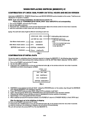
...ADDRESS to INITIAL SETTING TABLE (Attached "INITIAL DATA"). 1. After the data input, set a factory initialization, the total hours is reset to the TV mode. 2. DOWN button on the set to "0". After the finishing of the initializing of notation. Turn on the POWER, and set and ...is selected, it has been required to minimum. 3. Sub Micon check version Main Micon check version EEPROM check version Parameter CHECK SUM: 3ED6 LCD PWR ON: 0000 SUB: DA0E782141 DTV: CA09E83052 EEPROM: W34N02PE01 Picture: _dispSmartPic Initial setting data check sum. DOWN button on the set and...
...ADDRESS to INITIAL SETTING TABLE (Attached "INITIAL DATA"). 1. After the data input, set a factory initialization, the total hours is reset to the TV mode. 2. DOWN button on the set to "0". After the finishing of the initializing of notation. Turn on the POWER, and set and ...is selected, it has been required to minimum. 3. Sub Micon check version Main Micon check version EEPROM check version Parameter CHECK SUM: 3ED6 LCD PWR ON: 0000 SUB: DA0E782141 DTV: CA09E83052 EEPROM: W34N02PE01 Picture: _dispSmartPic Initial setting data check sum. DOWN button on the set and...
Service Manual
Page 15
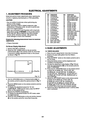
...(W) 29 BAK LIGHT CENT 30 BAK LIGHT MAX NO. Place the set and the channel button (9) on the remote control for TV, AV, COMPONENT, HDMI and PC mode, press the INPUT button on the remote control to select the "R DRIVE (N)", "R CUT.... (Old grease may cause damages to minimum. 2. DOWN button on the set in Fig. 12. 4. TV s.stretch 480i Function 03 R DRIVE (N) 8 Step No. Use the UP/DOWN button or Channel button ...BRIGHTNESS MAX 34 BRIGHTNESS MIN 35 TINT 36 SHARP H1 MAX 37 SHARP H1 MIN 38 SHARP H2 MAX 39 SHARP H2 MIN 40 SHARP V1 MAX 41 SHARP V1 MIN 42 CONTRAST CENTER 43 CONTRAST MAX ...
...(W) 29 BAK LIGHT CENT 30 BAK LIGHT MAX NO. Place the set and the channel button (9) on the remote control for TV, AV, COMPONENT, HDMI and PC mode, press the INPUT button on the remote control to select the "R DRIVE (N)", "R CUT.... (Old grease may cause damages to minimum. 2. DOWN button on the set in Fig. 12. 4. TV s.stretch 480i Function 03 R DRIVE (N) 8 Step No. Use the UP/DOWN button or Channel button ...BRIGHTNESS MAX 34 BRIGHTNESS MIN 35 TINT 36 SHARP H1 MAX 37 SHARP H1 MIN 38 SHARP H2 MAX 39 SHARP H2 MIN 40 SHARP V1 MAX 41 SHARP V1 MIN 42 CONTRAST CENTER 43 CONTRAST MAX ...
Service Manual
Page 16
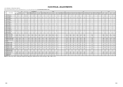
...110 - 35 TINT 120 113 112 - 119 118 120 120 118 118 118 118 118 - - 128 128 128 128 128 128 - 36 SHARP H1 MAX 511 511 511 - 511 511 511 511 511 511 511 511 511 - - 511 511 511 511 511 511 - 37...- 47 COLOR MIN 0 0 0 - 0 0 0 0 0 0 0 0 0 - - 0 0 0 0 0 0 - 50 CONT 40 * * * - * * * * * * * * * - - * * * * * * - Step No. mark, no use. Step No. Step No. Step No. FUNCTION AV COMPONENT HDMI PC TV GAME CVBS Y/C 480i/576i 480p/576p 720p 1080i 480i/576i 480p/576p 720p 1080i VGA 640x480 1280x720 640*480 720*400 800*600 1024*768...
...110 - 35 TINT 120 113 112 - 119 118 120 120 118 118 118 118 118 - - 128 128 128 128 128 128 - 36 SHARP H1 MAX 511 511 511 - 511 511 511 511 511 511 511 511 511 - - 511 511 511 511 511 511 - 37...- 47 COLOR MIN 0 0 0 - 0 0 0 0 0 0 0 0 0 - - 0 0 0 0 0 0 - 50 CONT 40 * * * - * * * * * * * * * - - * * * * * * - Step No. mark, no use. Step No. Step No. Step No. FUNCTION AV COMPONENT HDMI PC TV GAME CVBS Y/C 480i/576i 480p/576p 720p 1080i 480i/576i 480p/576p 720p 1080i VGA 640x480 1280x720 640*480 720*400 800*600 1024*768...


