Service Manual
Page 1
... maintaining the safety of the set should be restored to its original condition and only parts identical to those specified should be used. The contents are important for SHARP CORPORATION after sales service only. Be sure to change without notice. " are subject to replace these parts with " ! SERVICE MANUAL No.S480ILC26SB14 LCD COLOR TELEVISION MODEL LC-26SB14U In the interests of user-safety (Required by safety regulations...
... maintaining the safety of the set should be restored to its original condition and only parts identical to those specified should be used. The contents are important for SHARP CORPORATION after sales service only. Be sure to change without notice. " are subject to replace these parts with " ! SERVICE MANUAL No.S480ILC26SB14 LCD COLOR TELEVISION MODEL LC-26SB14U In the interests of user-safety (Required by safety regulations...
Service Manual
Page 2
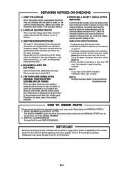
... diagram or the table of the heat sink. Make sure to the IC and Transistor). Therefore, the part which is indicated in your SERVICE MANUAL. The inside . Remove the antenna terminal on TV and turn on the contact section of parts as a tube or tape for safety. KEEP THE NOTICES As for safety which is less than 1M ohm by using...
... diagram or the table of the heat sink. Make sure to the IC and Transistor). Therefore, the part which is indicated in your SERVICE MANUAL. The inside . Remove the antenna terminal on TV and turn on the contact section of parts as a tube or tape for safety. KEEP THE NOTICES As for safety which is less than 1M ohm by using...
Service Manual
Page 4
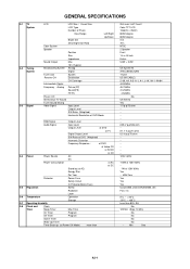
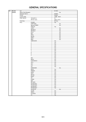
...G-3 Signal LCD LCD Size / Visual Size LCD Type Number of Pixels View Range Left/Right Up/Down Bright Dot Zero Bright Dot Ratio Color System Speaker Position Size Impedance Sound Output Max 10%(Typical) Broadcasting System Analog Digital Tuner and System Receive CH Destination CH Coverage Intermediate Digital Frequency Analog Picture(FP) Sound(FS) FP-FS Preset CH Stereo/Dual TV Sound Tuner Sound Muting Video Signal Input Level Output Level S/N Ratio (Weighted) Horizontal Resolution at DVD Mode RGB Signal Output Level Audio Signal Input Level Output Level...
...G-3 Signal LCD LCD Size / Visual Size LCD Type Number of Pixels View Range Left/Right Up/Down Bright Dot Zero Bright Dot Ratio Color System Speaker Position Size Impedance Sound Output Max 10%(Typical) Broadcasting System Analog Digital Tuner and System Receive CH Destination CH Coverage Intermediate Digital Frequency Analog Picture(FP) Sound(FS) FP-FS Preset CH Stereo/Dual TV Sound Tuner Sound Muting Video Signal Input Level Output Level S/N Ratio (Weighted) Horizontal Resolution at DVD Mode RGB Signal Output Level Audio Signal Input Level Output Level...
Service Manual
Page 5
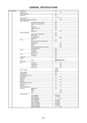
VIEW MODE 1 2 3 4 5 6 7 8 9 0 ENT INPUT FLASH BACK VOL+ VOLCH+ CHSURROUND MUTE FREEZE MENU LEFT ENTER RIGHT UP DOWN EXIT RETURN FAVORITE A FAVORITE B FAVORITE C FAVORITE D FAVORITE SLEEP AUDIO AV MODE CC RC-MQ No SHARP SHARP 10000 / 10001 3V UM-3 x 2 pcs 39 Keys Yes No ...Yes Yes Yes Yes No Yes Yes Yes Yes A2-2 G-9 Remote Control GENERAL SPECIFICATIONS Unit Glow in Dark Remocon Remocon Format Format Custom Code Power Source Voltage(D.C) UM size x pcs Total Keys Keys POWER FUNCTION Source POWER DISPLAY LIGHT SEARCH+ SEARCH- PLAY REC STOP PAUSE SKIP+ SKIP-
VIEW MODE 1 2 3 4 5 6 7 8 9 0 ENT INPUT FLASH BACK VOL+ VOLCH+ CHSURROUND MUTE FREEZE MENU LEFT ENTER RIGHT UP DOWN EXIT RETURN FAVORITE A FAVORITE B FAVORITE C FAVORITE D FAVORITE SLEEP AUDIO AV MODE CC RC-MQ No SHARP SHARP 10000 / 10001 3V UM-3 x 2 pcs 39 Keys Yes No ...Yes Yes Yes Yes No Yes Yes Yes Yes A2-2 G-9 Remote Control GENERAL SPECIFICATIONS Unit Glow in Dark Remocon Remocon Format Format Custom Code Power Source Voltage(D.C) UM size x pcs Total Keys Keys POWER FUNCTION Source POWER DISPLAY LIGHT SEARCH+ SEARCH- PLAY REC STOP PAUSE SKIP+ SKIP-
Service Manual
Page 6
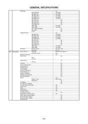
... Red, Green, Blue Auto Adjust Audio MTS Tone Control (Bass/Treble/Balance) Stable Sound Surround BBE SRS WOW (SRS 3D/Focus/Tru Bass) Variable Audio Out Tuning CH Program Air/Cable ADD/DELETE Label CH Label Video Label Favorite CH V-Chip Type RRT Setup Lock Hotel Lock Channel Lock Video Lock Panel Lock Menu Language Closed Caption CC Advanced View Mode (Picture Size) Picture Scroll Film Mode Aspect Backlight PFC(Power Factor circuit) Freeze frame PIP/POP Direct Input Selection Digital Out Dolby Digital MPEG...
... Red, Green, Blue Auto Adjust Audio MTS Tone Control (Bass/Treble/Balance) Stable Sound Surround BBE SRS WOW (SRS 3D/Focus/Tru Bass) Variable Audio Out Tuning CH Program Air/Cable ADD/DELETE Label CH Label Video Label Favorite CH V-Chip Type RRT Setup Lock Hotel Lock Channel Lock Video Lock Panel Lock Menu Language Closed Caption CC Advanced View Mode (Picture Size) Picture Scroll Film Mode Aspect Backlight PFC(Power Factor circuit) Freeze frame PIP/POP Direct Input Selection Digital Out Dolby Digital MPEG...
Service Manual
Page 7
...;720p 1920×1080i Wall Mount Size W x H(mm) Screw Size Owner's Manual Language w/Guarantee Card Remote Control Unit Rod Antenna Poles Terminal Loop Antenna Terminal U/V Mixer DC Car Cord (Center+) Guarantee Card Warning Sheet Circuit Diagram Antenna Change Plug Service Facility List Important Safeguard Dew/AHC Caution Sheet Quick Set-up Sheet Battery UM size x pcs OEM Brand AC Adapter AC Cord (for AC Adapter) AC Cord (Flat Polarity Plugs) Cable Cramp Stand Stand Screw Hexagon Wrench AV Cord (2Pin-1Pin) Registration...
...;720p 1920×1080i Wall Mount Size W x H(mm) Screw Size Owner's Manual Language w/Guarantee Card Remote Control Unit Rod Antenna Poles Terminal Loop Antenna Terminal U/V Mixer DC Car Cord (Center+) Guarantee Card Warning Sheet Circuit Diagram Antenna Change Plug Service Facility List Important Safeguard Dew/AHC Caution Sheet Quick Set-up Sheet Battery UM size x pcs OEM Brand AC Adapter AC Cord (for AC Adapter) AC Cord (Flat Polarity Plugs) Cable Cramp Stand Stand Screw Hexagon Wrench AV Cord (2Pin-1Pin) Registration...
Service Manual
Page 8
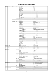
... H (mm) w/o Handle, Stand Approx. GENERAL SPECIFICATIONS G-12 Interface G-13 Set Size G-14 Weight G-15 Carton G-16 Material G-17 Environment Switch Indicator Terminals Top Power (Tact) Channel Up Channel Down Volume Up Volume Down Menu Play Eject Skip+, Search+ Skip-, Search- Input 2 Video Output Audio Output Component Input 1 Analog Audio Component Input 2 Analog Audio HDMI Input 1 Analog Audio HDMI Input 2 Analog Audio Sub Woofer Out PC Monitor Input Analog Audio Digital Audio Output DC Jack (Center +) VHF/UHF Antenna Input Video Input 3 Audio Input 3 S -
... H (mm) w/o Handle, Stand Approx. GENERAL SPECIFICATIONS G-12 Interface G-13 Set Size G-14 Weight G-15 Carton G-16 Material G-17 Environment Switch Indicator Terminals Top Power (Tact) Channel Up Channel Down Volume Up Volume Down Menu Play Eject Skip+, Search+ Skip-, Search- Input 2 Video Output Audio Output Component Input 1 Analog Audio Component Input 2 Analog Audio HDMI Input 1 Analog Audio HDMI Input 2 Analog Audio Sub Woofer Out PC Monitor Input Analog Audio Digital Audio Output DC Jack (Center +) VHF/UHF Antenna Input Video Input 3 Audio Input 3 S -
Service Manual
Page 13
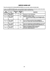
... both buttons simultaneously on the main unit and on the remote control for more than a the standard time in the appropriate condition. (See below chart.) Set Condition Power ON Set Key VOL. DOWN (Minimum) Remocon Key 0 Power ON VOL. SERVICE MODE LIST This unit is provided with the following SERVICE MODES so you set factory initialization, the memories are reset such as the channel setting, and the POWER ON...
... both buttons simultaneously on the main unit and on the remote control for more than a the standard time in the appropriate condition. (See below chart.) Set Condition Power ON Set Key VOL. DOWN (Minimum) Remocon Key 0 Power ON VOL. SERVICE MODE LIST This unit is provided with the following SERVICE MODES so you set factory initialization, the memories are reset such as the channel setting, and the POWER ON...
Service Manual
Page 14
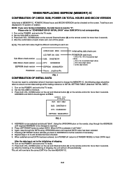
... button on the set and Channel button (6) on the POWER, and set to the initializing of shipping. 10. Set the VOLUME to "0". When DATA is now selected and should "blink". Turn on the remote control for more than 2 seconds. 4. POWER ON total hours. = (16 x 16 x 16 x thousands digit value) + (16 x 16 x hundreds digit value) + (16 x tens digit value) + (ones digit value) FIG. 1 CONFIRMATION OF INITIAL DATA If a service repair...
... button on the set and Channel button (6) on the POWER, and set to the initializing of shipping. 10. Set the VOLUME to "0". When DATA is now selected and should "blink". Turn on the remote control for more than 2 seconds. 4. POWER ON total hours. = (16 x 16 x 16 x thousands digit value) + (16 x 16 x hundreds digit value) + (16 x tens digit value) + (ones digit value) FIG. 1 CONFIRMATION OF INITIAL DATA If a service repair...
Service Manual
Page 15
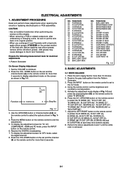
... perform these adjustments when repairing the circuits or replacing electrical parts or PCB assemblies. To display the adjustment screen for DTV mode, select the digital channel. 8. Place the set the brightness and contrast to the AV mode. 4. DOWN button on the set and the channel (9) on the screen as shown in Aging Test for more than 2 seconds. Perform the above adjustments 6 and 7 until the white color is achieved. TV s.stretch 480i...
... perform these adjustments when repairing the circuits or replacing electrical parts or PCB assemblies. To display the adjustment screen for DTV mode, select the digital channel. 8. Place the set the brightness and contrast to the AV mode. 4. DOWN button on the set and the channel (9) on the screen as shown in Aging Test for more than 2 seconds. Perform the above adjustments 6 and 7 until the white color is achieved. TV s.stretch 480i...
Service Manual
Page 16
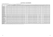
...100 - - 100 100 100 100 100 100 - 31 BAK LIGHT MIN 0 0 0 - 0 0 0 0 0 0 0 ...SHARP H1 MAX 511 511 511 -...COLOR MIN 0 0 0 - 0 0 0 0 0 0 0 0 0 - - 0 0 0 0 0 0 - 50 CONT 40 * * * - * * * * * * * * * - - * * * * * * - with * mark, please adjust it according to the situation of the adjustment item is set . Step No. Step No. FUNCTION AV COMPONENT HDMI PC TV GAME... ADJUSTMENTS 2-2: Confirmation of Fixed Value (Step No.) Please check if the fixed values of each of the set correctly referring below. (TV/AV/COMPONENT/HDMI/PC/DTV)...
...100 - - 100 100 100 100 100 100 - 31 BAK LIGHT MIN 0 0 0 - 0 0 0 0 0 0 0 ...SHARP H1 MAX 511 511 511 -...COLOR MIN 0 0 0 - 0 0 0 0 0 0 0 0 0 - - 0 0 0 0 0 0 - 50 CONT 40 * * * - * * * * * * * * * - - * * * * * * - with * mark, please adjust it according to the situation of the adjustment item is set . Step No. Step No. FUNCTION AV COMPONENT HDMI PC TV GAME... ADJUSTMENTS 2-2: Confirmation of Fixed Value (Step No.) Please check if the fixed values of each of the set correctly referring below. (TV/AV/COMPONENT/HDMI/PC/DTV)...
Service Manual
Page 18
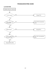
Yes Change DIGITAL PCB. Check IC401 and peripheral circuit. E-1 No No Is there voltage at pin No 10 of IC402 6V? Change F401. Change R412. (LCD SECTION) POWER DOES NOT TURN ON TROUBLESHOOTING GUIDE Yes Is F401 broken? No Is there voltage at pin 1 of IC401 19V? Yes Yes Is R412 broken? Check IC402 and peripheral circuit.
Yes Change DIGITAL PCB. Check IC401 and peripheral circuit. E-1 No No Is there voltage at pin No 10 of IC402 6V? Change F401. Change R412. (LCD SECTION) POWER DOES NOT TURN ON TROUBLESHOOTING GUIDE Yes Is F401 broken? No Is there voltage at pin 1 of IC401 19V? Yes Yes Is R412 broken? Check IC402 and peripheral circuit.
Service Manual
Page 20
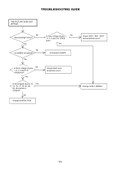
Yes Is there signal at pins No 1, 2, 3, 4 and 5 of CP2804 5V? Change V2301 (PANEL). Yes No Is CD2804 connected? No Change DIGITAL PCB. Check IC407 and peripheral circuit. Check IC401, T401, D437 and peripheral circuit. Yes Is there voltage at pins 13, Yes 14, 16, 17, 19, 20, 22, 23, 25 and 26 of CP406 24V? Yes Connected CD2804. E-3 TROUBLESHOOTING GUIDE THE PICTURE DOES NOT APPEAR No Does backlight shine? Is there voltage at pins 1, No 2, 3, 4 and 5 of CP2804?
Yes Is there signal at pins No 1, 2, 3, 4 and 5 of CP2804 5V? Change V2301 (PANEL). Yes No Is CD2804 connected? No Change DIGITAL PCB. Check IC407 and peripheral circuit. Check IC401, T401, D437 and peripheral circuit. Yes Is there voltage at pins 13, Yes 14, 16, 17, 19, 20, 22, 23, 25 and 26 of CP406 24V? Yes Connected CD2804. E-3 TROUBLESHOOTING GUIDE THE PICTURE DOES NOT APPEAR No Does backlight shine? Is there voltage at pins 1, No 2, 3, 4 and 5 of CP2804?
Service Manual
Page 21
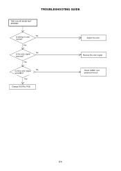
Adjust the color. E-4 TROUBLESHOOTING GUIDE THE COLOR DOES NOT APPEAR No Is setting of color normal? Yes Change DIGITAL PCB. Check IC2801 and peripheral circuit. Receive the color signal. Yes No Is the color signal received? Yes No Is there color signal at IC2801?
Adjust the color. E-4 TROUBLESHOOTING GUIDE THE COLOR DOES NOT APPEAR No Is setting of color normal? Yes Change DIGITAL PCB. Check IC2801 and peripheral circuit. Receive the color signal. Yes No Is the color signal received? Yes No Is there color signal at IC2801?
Service Manual
Page 29
... B11 D3 D11 D2 B10 D1 D10 D0 NOTE:THIS SCHEMATIC DIAGRAM IS THE LATEST AT THE TIME OF PRINTING AND SUBJECT TO CHANGE WITHOUT NOTICE NOTE:THE DC VOLTAGE AT EACH PART WAS MEASURED WITH THE DIGITAL TESTER WHEN THE COLOR BROADCAST WAS RECEIVED IN GOOD CONDITION AND PICTURE IS NORMAL. PC_TOOL_RX PC_TOOL_TX HDMI_SW A_MUTE JG2803 JG2804 JG2805...
... B11 D3 D11 D2 B10 D1 D10 D0 NOTE:THIS SCHEMATIC DIAGRAM IS THE LATEST AT THE TIME OF PRINTING AND SUBJECT TO CHANGE WITHOUT NOTICE NOTE:THE DC VOLTAGE AT EACH PART WAS MEASURED WITH THE DIGITAL TESTER WHEN THE COLOR BROADCAST WAS RECEIVED IN GOOD CONDITION AND PICTURE IS NORMAL. PC_TOOL_RX PC_TOOL_TX HDMI_SW A_MUTE JG2803 JG2804 JG2805...
Service Manual
Page 37
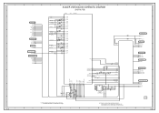
... 12 +30V 14 SDA 15 SCL 16 AFT 17 +5V 18 IF_OUT 19 IF_AGC 20 IF_OUT1 21 IF_OUT2 D E TUNER SCHEMATIC DIAGRAM (DIGITAL PCB) 24 25 L5801 22uHNLV25 F W878 8 G TO SCALER VIDEO/AUDIO TU_CVBS H 8 7 3.3 3.3 2.6 5.0 B5809 0 FCM1608KF-102T02 NC 0.9 0.2 0.4 2.0 NC 1.5 5.0 B5808 ...PART WAS MEASURED NOTE:THIS SCHEMATIC DIAGRAM IS THE LATEST AT THE TIME WITH THE DIGITAL TESTER WHEN THE COLOR BROADCAST OF PRINTING AND SUBJECT TO CHANGE WITHOUT NOTICE WAS RECEIVED IN GOOD CONDITION AND PICTURE IS NORMAL. CAUTION:SINCE THESE PARTS MARKED BY ARE CRITICAL FOR SAFETY,USE ONES DESCRIBED IN PARTS LIST...
... 12 +30V 14 SDA 15 SCL 16 AFT 17 +5V 18 IF_OUT 19 IF_AGC 20 IF_OUT1 21 IF_OUT2 D E TUNER SCHEMATIC DIAGRAM (DIGITAL PCB) 24 25 L5801 22uHNLV25 F W878 8 G TO SCALER VIDEO/AUDIO TU_CVBS H 8 7 3.3 3.3 2.6 5.0 B5809 0 FCM1608KF-102T02 NC 0.9 0.2 0.4 2.0 NC 1.5 5.0 B5808 ...PART WAS MEASURED NOTE:THIS SCHEMATIC DIAGRAM IS THE LATEST AT THE TIME WITH THE DIGITAL TESTER WHEN THE COLOR BROADCAST OF PRINTING AND SUBJECT TO CHANGE WITHOUT NOTICE WAS RECEIVED IN GOOD CONDITION AND PICTURE IS NORMAL. CAUTION:SINCE THESE PARTS MARKED BY ARE CRITICAL FOR SAFETY,USE ONES DESCRIBED IN PARTS LIST...
Service Manual
Page 38
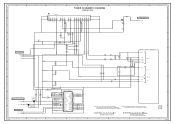
...TUNER TU_CVBS I2C_CLK I2C_DATA TO HDMI HP_RST FROM SCALER POWER AD_A3.3V FROM/TO AV SWITCH2 SW_Y_IN SW_C_IN MCLK SDOUT LRCK BCLK C D E F SCALER VIDEO/AUDIO SCHEMATIC DIAGRAM (DIGITAL... 0.1 B V8 3.3 SCIRXD V7 3.3 SCISCK(GPIO) W73.3 C2965 0.1 B ASW0 ASW1 ASW2 VDIM LCD-H MCU_SCIRXD MCU_SCITXD IIC_OFF NC 4321 0 A0 0 A1 0 A2 0 Vss Vcc WP SCL SDA 5678...SCHEMATIC DIAGRAM IS THE LATEST AT THE TIME OF PRINTING AND SUBJECT TO CHANGE WITHOUT NOTICE B C D NOTE:THE DC VOLTAGE AT EACH PART WAS MEASURED WITH THE DIGITAL TESTER WHEN THE COLOR BROADCAST WAS RECEIVED IN GOOD CONDITION AND PICTURE...
...TUNER TU_CVBS I2C_CLK I2C_DATA TO HDMI HP_RST FROM SCALER POWER AD_A3.3V FROM/TO AV SWITCH2 SW_Y_IN SW_C_IN MCLK SDOUT LRCK BCLK C D E F SCALER VIDEO/AUDIO SCHEMATIC DIAGRAM (DIGITAL... 0.1 B V8 3.3 SCIRXD V7 3.3 SCISCK(GPIO) W73.3 C2965 0.1 B ASW0 ASW1 ASW2 VDIM LCD-H MCU_SCIRXD MCU_SCITXD IIC_OFF NC 4321 0 A0 0 A1 0 A2 0 Vss Vcc WP SCL SDA 5678...SCHEMATIC DIAGRAM IS THE LATEST AT THE TIME OF PRINTING AND SUBJECT TO CHANGE WITHOUT NOTICE B C D NOTE:THE DC VOLTAGE AT EACH PART WAS MEASURED WITH THE DIGITAL TESTER WHEN THE COLOR BROADCAST WAS RECEIVED IN GOOD CONDITION AND PICTURE...
Service Manual
Page 41
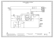
... SCHEMATIC DIAGRAM IS THE LATEST AT THE TIME OF PRINTING AND SUBJECT TO CHANGE WITHOUT NOTICE NOTE:THE DC VOLTAGE AT EACH PART WAS MEASURED WITH THE DIGITAL TESTER WHEN THE COLOR BROADCAST WAS RECEIVED IN GOOD CONDITION AND PICTURE IS NORMAL. ATTENTION:POUR UNE PROTECTION CONTINUE LES RISQUES D'INCEIE N'UTILISER QUE DES FUSIBLE DE MEME TYPE 1 6.3A 125V(F401). A B C D E F G H POWER SCHEMATIC DIAGRAM...
... SCHEMATIC DIAGRAM IS THE LATEST AT THE TIME OF PRINTING AND SUBJECT TO CHANGE WITHOUT NOTICE NOTE:THE DC VOLTAGE AT EACH PART WAS MEASURED WITH THE DIGITAL TESTER WHEN THE COLOR BROADCAST WAS RECEIVED IN GOOD CONDITION AND PICTURE IS NORMAL. ATTENTION:POUR UNE PROTECTION CONTINUE LES RISQUES D'INCEIE N'UTILISER QUE DES FUSIBLE DE MEME TYPE 1 6.3A 125V(F401). A B C D E F G H POWER SCHEMATIC DIAGRAM...
Service Manual
Page 42
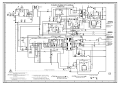
...TIME OF PRINTING AND SUBJECT TO CHANGE WITHOUT NOTICE NOTE:THE DC VOLTAGE AT EACH PART WAS MEASURED WITH THE DIGITAL TESTER WHEN THE COLOR BROADCAST WAS RECEIVED IN GOOD CONDITION AND PICTURE IS NORMAL. CAUTION:F404 IS MANUFACTURED BY SKYGATE CO.,LTD., TYPE 20N. A B C D E F POWER2 SCHEMATIC DIAGRAM 8 (POWER PCB) G H 8 7 FROM POWER INV_SW+24V SW+12V[UNREG] AT+5V P_GND INV_GND INV_GND 6 LCD...Q423 KTC3875S_Y_RTK L408 47uH 1315 R483 R484 8.2K 820 +-1% +-1% LCD+B SW 0 Q411 KRC102SRTK 3.2 0 PANEL_POWER_H LCD-H TO SOUND P.CON+5V R493_1 2.2K R470 560 1/4W P_GND 4 P....
...TIME OF PRINTING AND SUBJECT TO CHANGE WITHOUT NOTICE NOTE:THE DC VOLTAGE AT EACH PART WAS MEASURED WITH THE DIGITAL TESTER WHEN THE COLOR BROADCAST WAS RECEIVED IN GOOD CONDITION AND PICTURE IS NORMAL. CAUTION:F404 IS MANUFACTURED BY SKYGATE CO.,LTD., TYPE 20N. A B C D E F POWER2 SCHEMATIC DIAGRAM 8 (POWER PCB) G H 8 7 FROM POWER INV_SW+24V SW+12V[UNREG] AT+5V P_GND INV_GND INV_GND 6 LCD...Q423 KTC3875S_Y_RTK L408 47uH 1315 R483 R484 8.2K 820 +-1% +-1% LCD+B SW 0 Q411 KRC102SRTK 3.2 0 PANEL_POWER_H LCD-H TO SOUND P.CON+5V R493_1 2.2K R470 560 1/4W P_GND 4 P....
Service Manual
Page 55
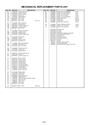
... HINGE 121 761WSA0480 ANGLE MAIN 122 761WSBA016 PLATE JACK 123 800WR00084 DAMPER SPEAKER 124 722000A655 SHEET SERIAL 125 723000D739 MERCURY CAUTION LABEL (SHARP) 126 723527A123 SHEET RATING 127 723000D814 SHEET JACK 128 723000D799 POP LABEL 129 800WQ00127 FELT SHEET 130 800WQ00134 FELT SHEET 40*60*T0.5 REF. JB5ND000 POLYBAG,INSTRUCTION(RED CAUTION) K1-1 MECHANICAL REPLACEMENT PARTS LIST REF.
... HINGE 121 761WSA0480 ANGLE MAIN 122 761WSBA016 PLATE JACK 123 800WR00084 DAMPER SPEAKER 124 722000A655 SHEET SERIAL 125 723000D739 MERCURY CAUTION LABEL (SHARP) 126 723527A123 SHEET RATING 127 723000D814 SHEET JACK 128 723000D799 POP LABEL 129 800WQ00127 FELT SHEET 130 800WQ00134 FELT SHEET 40*60*T0.5 REF. JB5ND000 POLYBAG,INSTRUCTION(RED CAUTION) K1-1 MECHANICAL REPLACEMENT PARTS LIST REF.


