Sharp LC-26SB14U Support Question
Sharp LC-26SB14U Support Question
Find answers below for this question about Sharp LC-26SB14U - 26" LCD TV.Need a Sharp LC-26SB14U manual? We have 1 online manual for this item!
Question posted by rsdecade on March 2nd, 2011
I Have A Common Problem With Sharp Tv's I Have A White Screen. The Caps Are O
white screen, we all know that this tv is not worth a lot of money to compensate buying a 100 plus board. I am looking for info how to fix the board.
Current Answers
Related Sharp LC-26SB14U Manual Pages
Service Manual - Page 1
...has been published to be used for
SHARP CORPORATION after sales service only. CONTENTS
...BOARDS G-1~G-8 • SCHEMATIC DIAGRAMS ...H-1~H-40 • WAVEFORMS ...I-1, I-2 • MECHANICAL EXPLODED VIEWS J-1 • REPLACEMENT PARTS LIST K1-1~K2-6
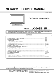
Parts marked with specified ones for maintaining the safety of the set. SERVICE MANUAL
No.S480ILC26SB14
LCD COLOR TELEVISION
MODEL LC-26SB14U...
Service Manual - Page 2
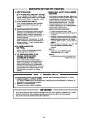
... or external metal and the AC cord plug blades. and DESCRIPTION You can be found on the TV. 3. KEEP THE NOTICES
As for safety which use a Tester.
[Note 2] External exposure metal...
Please include the following informations when you exchange IC and Transistor with the printed board. BE CAREFUL WITH THE LCD PANEL
Avoid a shock to keep the indications and notices in the circuit diagram or the...
Service Manual - Page 3
...-2
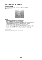
In case of using lead free solder will tend to splash when heated too high (about 1100oF/ 600oC). • All products with the printed circuit board with PbF printing must be sure to heat the soldering points with the lead free solder until it to 650oF ± 20oF (350oC ± 10oC...
Service Manual - Page 4
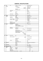
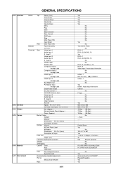
GENERAL SPECIFICATIONS
G-1 TV System
G-2 Tuning System
G-3 Signal
LCD
LCD Size / Visual Size
LCD Type
Number of Pixels
View Range
Left/Right
Up/...CH
Destination
CH Coverage
Intermediate Digital
Frequency Analog Picture(FP)
Sound(FS)
FP-FS
Preset CH
Stereo/Dual TV Sound
Tuner Sound Muting
Video Signal
Input Level
Output Level
S/N Ratio (Weighted)
Horizontal Resolution at DVD ...
Service Manual - Page 5
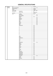
...+ VOLCH+ CHSURROUND MUTE FREEZE MENU LEFT ENTER RIGHT UP DOWN EXIT RETURN FAVORITE A FAVORITE B FAVORITE C FAVORITE D FAVORITE SLEEP AUDIO AV MODE CC
RC-MQ No
SHARP SHARP 10000 / 10001 3V UM-3 x 2 pcs 39 Keys Yes
No No Yes No No No No No No No No No Yes Yes Yes Yes Yes...
Service Manual - Page 6
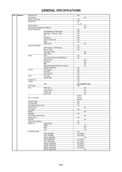
...Filter
Game Position
Auto Setup(Language/CH Program)
Picture Setting(TV)
AV Mode(Picture Preference)
Brightness , Contrast , Color
Tint
Sharpness
Color Temperature
DNR
Cable Clear
Picture Setting(PC)
HOR Position...Favorite CH
V-Chip
Type
RRT Setup
Lock
Hotel Lock
Channel Lock
Video Lock
Panel Lock
Menu Language
Closed Caption
CC Advanced
View Mode (Picture Size)
Picture ...
Service Manual - Page 7
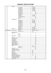
...-up Sheet
Battery
UM size x pcs
OEM Brand
AC Adapter
AC Cord (for AC Adapter)
AC Cord (Flat Polarity Plugs)
Cable Cramp
Stand
Stand Screw
Hexagon Wrench
AV Cord (2Pin-1Pin)
Registration Card (NDL Card)
...Yes Yes (60Hz) Yes (60Hz) Yes (60Hz) Yes (60Hz) No No No No Yes (60Hz) Yes (60Hz) Yes (100 x 100) M4 x 10 English/French/Spanish Yes Yes No --No -No No No No No No No No No No Yes UM-3...
Service Manual - Page 8
...Container Stuffing (40' container)
w/Pallet
w/Wrapping
Cabinet Front
Rear
Jack Panel
PCB
Non-Halogen Demand
Eyelet Demand
Environmental standard requirement
Pb-free
Measures...Description of Origin
Gift Box Material
W/Color Photo Label
W/Handle
Dimensions W x D x H(mm)
Description of SHARP
Phase3(Phase3A)
Yes
Yes
A2-5 Input 1
Video Input 2
Audio Input 2
S - Input 3
Other ...
Service Manual - Page 9
...connectors: (CP302, CP2804 and CP4303).
2. Remove the 2 screws (2). 6. Holder Panel
Angle Main (2)
(2) (2)
(2)
(1) Angle Main (1) (1)
LCD Block
(1)
(A)
Holder Panel
Plate Button Ass'y
(1) (1)
(1) (B)
Operation PCB (3) (2)
(3)
(3)
(A) (C)
(3) (3) (3)
Angle Hinge
Fig. 1-4
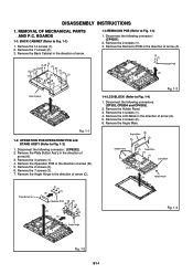
Fig. 1-2 B1-1 BOARDS
1-1: BACK CABINET (Refer to Fig. 1-2)
1. Disconnect the following connector: (CP6202...
Service Manual - Page 10
Remove the 5 screws (2). 4. Remove the 5 screws (5). 8. Remove the 4 screws (1). 2. Remove the Cover LCD in the
direction of arrow.
(2)
(1) (1)
(1) (1)
Cover LCD
LCD Panel
(B)
Fig. 1-7
Fig. 1-6
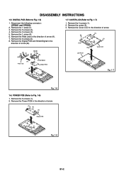
1-6: POWER PCB (Refer to Fig. 1-7)
1. Remove the Digital PCB and Shield Digital in the direction of arrow (B).
(2) (3)
(1)
(2) (4)
(5) (5)
(5)
(5) (5)
(A) Plate Jack
Shield ...
Service Manual - Page 11
... IC when removing it. Peel off the Masking Tape.
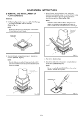
5. DISASSEMBLY INSTRUCTIONS
2. REMOVAL AND INSTALLATION OF FLAT PACKAGE IC
REMOVAL
1. Braided Shield Wire
Soldering Iron
IC
Fig. 2-2
IC pattern
Fig. 2-4
B2-1...and forth easily after desoldering the leads completely. Put Masking Tape (cotton tape) around the Flat Package IC to protect other parts from any damage. (Refer to Fig. 2-2.) NOTE Do...
Service Manual - Page 13
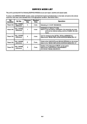
...channel setting, and the POWER ON total hours.
Refer to the "ELECTRICAL ADJUSTMENT" (On-Screen Display Adjustment). Display of V-CHIP PASSWORD.
2 sec. Power ON
VOL.
C-1 DOWN (Minimum...)
1
Standard Time
Operations
2 sec.
Releasing of the Adjustment MENU on the screen. Check of factory TV data. Refer to the "WHEN REPLACING EEPROM (MEMORY) IC".
Initialization of the...
Service Manual - Page 14
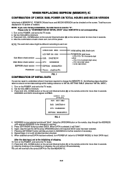
...to finish DATA input.
ADDRESS is not corresponding. 1. Using the UP/DOWN buton on the screen. Press LEFT/RIGHT button to "CONFIRMATION OF INITIAL DATA" when SUM DATA is now selected ...After the data input, set to the TV mode. 2. Press both VOL. C-2
Sub Micon check version Main Micon check version
EEPROM check version Parameter
CHECK SUM: 3ED6 LCD PWR ON: 0000 SUB: DA0E782141 DTV:...
Service Manual - Page 15
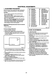
...Screen Display Adjustment
1. Set the VOLUME to normal position. 5. Fig. 1-1
3. Receive the DIGITAL broadcasting. 7. FUNCTION 31 BAK LIGHT MIN 32 BRIGHTNESS CENT 33 BRIGHTNESS MAX 34 BRIGHTNESS MIN 35 TINT 36 SHARP H1 MAX 37 SHARP H1 MIN 38 SHARP H2 MAX 39 SHARP H2 MIN 40 SHARP V1 MAX 41 SHARP... adjustments 6 and 7 until the white color is achieved. D-1 TV s.stretch 480i
Function
03 R DRIVE...
Service Manual - Page 16
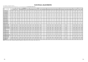
...Fixed Value (Step No.) Please check if the fixed values of each of the set correctly referring below. (TV/AV/COMPONENT/HDMI/PC/DTV)
NO. FUNCTION
AV
COMPONENT
HDMI
PC
TV...50
50
50
-
-
50
50
50
50
50
50
-
30 BAK LIGHT MAX
100 100 100 - 100 100 100 100 100 100 100 100 100
-
-
100 100 100 100 100 100
-
31 BAK LIGHT MIN
0
0
0
-
0
0
0
0
0
0
...SHARP H1 MAX
511 511 511 -...
Service Manual - Page 18
Yes
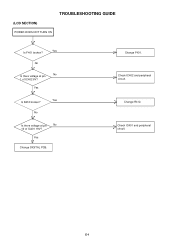
Change DIGITAL PCB.
Check IC402 and peripheral circuit. Change R412. Check IC401 and peripheral circuit. No
No Is there voltage at pin
No
10 of IC402 6V?
Yes
Yes Is R412 broken?
Change F401.
(LCD SECTION)
POWER DOES NOT TURN ON
TROUBLESHOOTING GUIDE
Yes Is F401 broken?
No
Is there voltage at pin 1 of IC401 19V? E-1
Service Manual - Page 41
... IN PARTS LIST ONLY
CAUTION: DIGITAL TRANSISTOR
F
G
2
PCB240 CEG353
1
H
H-26
A
B
C
D
E
F
G
H
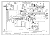
POWER SCHEMATIC DIAGRAM
8
F401 6.3A125V
6.3A...FH402 003P-2100
EYF-52BCY
D404_1 ENE241D-10A-Q6
1
WHITE
WHITE
7
D402
1
2
3
4
COIL,LINE FILTER ...
R541
180K
D433 1H3-E
R441 15K 5.0
FEED BACK IC410
1H3-E 100 1/4W
PS2561AL1-1-V(W) R443
1K
1.0
5.0
R546 10K
5.0
BUFFER
D
...
Service Manual - Page 49
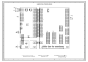
...CEG353
NC
E1 CVBS_IN_1
J4206
3245
H1 H2 H3
NC
CD3805
J401
2
BLACK
1
WHITE
PC/DVI AUDIO IN J4201
567 12
34
CP401
TUNER+30V 1 1
POWER_FAIL 2...RXIN1+
22
RXIN1-
23
GND
24
RXIN0+
25
RXIN0-
26
GND
27
GND
28
VDD+3.3V/NC/GND 29 NC VDD... 6 RESET_N 7 FLASH_WP 8 ASEMD0 9 GND 10 VDD33 11 GND 12
CD2804
V2301_1 LCD PANEL
24
DIGITAL PCB PCBDH0 CEG352
SIF-out 5
AGC 7 NC V_OUT 8
+5V ...
Service Manual - Page 55
...
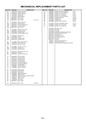
COVER LCD ASS'Y COVER LCD SPRING EARTH...PANEL
115
761WPA0473 HOLDER SPEAKER-L
116
761WPA0474 HOLDER SPEAKER-R
117
761WPA0477 COVER HINGE
118
723000D908 SHEET BARCODE
119
723000D909 SHEET BARCODE
120
761WSA0466 ANGLE HINGE
121
761WSA0480 ANGLE MAIN
122
761WSBA016 PLATE JACK
123
800WR00084 DAMPER SPEAKER
124
722000A655 SHEET SERIAL
125
723000D739 MERCURY CAUTION LABEL (SHARP...
Service Manual - Page 62
No part of this publication may be reproduced, stored in a retrieval system, or transmitted in any form or by any means, electronic, mechanical, photocopying, recording, or otherwise, without prior written permission of the publisher.
SHARP ELECTRONICS CORPORATION Sharp Plaza. Mahwah, New Jersey 07430-2135
COPYRIGHT © 2008 BY SHARP CORPORATION
ALL RIGHTS RESERVED.
Similar Questions

White Screen Problem With Lcd Tv Lc26sb14u
How to troubleshoot and repair ?
How to troubleshoot and repair ?
(Posted by thl748 11 years ago)

What To Do When Screen Is All White
(Posted by ladeannalloyd 12 years ago)

Problem - Tv Turns Off As Soon As I Turn It On - How Do I Fix?
(Posted by wdhalsey 12 years ago)
Where Can I Purchase A Lcd Screen For My Lc-46sb54u Flat Panel Tv Brand Is Shar
(Posted by allwayswillbe 12 years ago)
