Sharp LC-26SB14U Support Question
Sharp LC-26SB14U Support Question
Find answers below for this question about Sharp LC-26SB14U - 26" LCD TV.Need a Sharp LC-26SB14U manual? We have 1 online manual for this item!
Question posted by thl748 on December 1st, 2012
White Screen Problem With Lcd Tv Lc26sb14u
How to troubleshoot and repair ?
Current Answers
Answer #1: Posted by TVDan on December 1st, 2012 4:12 PM
TVDan

Member since:
August 8th, 2011 Points: 4,732,000

Member since:
August 8th, 2011 Points: 4,732,000
I've seen problems with the +5vdc supply to the LCD panel cause this problem, and other times it's the panel itself. check for this voltage on pins 11 and 12 of plug CP401. If it's missing suspect IC407 (LA5779). Pin 1 has +12vdc, pin 2 is the +5vdc output and pin 5 is the on/off control forthis IC (0vdc is on).
TV Dan
Related Sharp LC-26SB14U Manual Pages
Service Manual - Page 1
...-6
Parts marked with specified ones for maintaining the safety and performance of the set.
Be sure to change without notice. SERVICE MANUAL
No.S480ILC26SB14
LCD COLOR TELEVISION
MODEL LC-26SB14U
In the interests of user-safety (Required by safety regulations in some countries) the set should be restored to its original condition and only...
Service Manual - Page 2
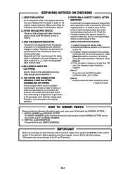
BE CAREFUL WITH THE LCD PANEL
Avoid a shock to ...there are put these do not contact with the labels or seals on the TV. 3. IMPORTANT
When you exchange IC and Transistor with it in this equipment ...material such as a mark, the designated parts must be more than 1M ohm, the inspection repair should be required.
[Note 1] If you order parts. (Particularly the VERSION LETTER.) 1....
Service Manual - Page 4
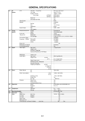
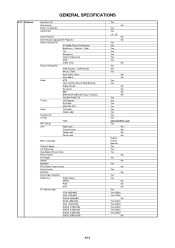
GENERAL SPECIFICATIONS
G-1 TV System
G-2 Tuning System
G-3 Signal
LCD
LCD Size / Visual Size
LCD Type
Number of Pixels
View Range
Left/Right
Up/...CH
Destination
CH Coverage
Intermediate Digital
Frequency Analog Picture(FP)
Sound(FS)
FP-FS
Preset CH
Stereo/Dual TV Sound
Tuner Sound Muting
Video Signal
Input Level
Output Level
S/N Ratio (Weighted)
Horizontal Resolution at DVD ...
Service Manual - Page 6
... Search Power On Memory Comb Filter
Game Position
Auto Setup(Language/CH Program)
Picture Setting(TV)
AV Mode(Picture Preference)
Brightness , Contrast , Color
Tint
Sharpness
Color Temperature
DNR
Cable...Label
Favorite CH
V-Chip
Type
RRT Setup
Lock
Hotel Lock
Channel Lock
Video Lock
Panel Lock
Menu Language
Closed Caption
CC Advanced
View Mode (Picture Size)
Picture Scroll
...
Service Manual - Page 9
... the following connector:
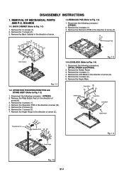
(CP4201). 2. REMOVAL OF MECHANICAL PARTS AND P.C. Remove the Operation PCB in the direction of arrow (B). 5. Holder Panel
Angle Main (2)
(2) (2)
(2)
(1) Angle Main (1) (1)
LCD Block
(1)
(A)
Holder Panel
Plate Button Ass'y
(1) (1)
(1) (B)
Operation PCB (3) (2)
(3)
(3)
(A) (C)
(3) (3) (3)
Angle Hinge
Fig. 1-4
Fig. 1-2 B1-1 Remove the...
Service Manual - Page 10
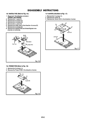
... in the direction of arrow.
(2)
(1) (1)
(1) (1)
Cover LCD
LCD Panel
(B)
Fig. 1-7
Fig. 1-6
1-6: POWER PCB (Refer to Fig. 1-6)
1. Remove the Power PCB in the direction of arrow.
(1) (1)
... in the direction of arrow (B).
(2) (3)
(1)
(2) (4)
(5) (5)
(5)
(5) (5)
(A) Plate Jack
Shield Digital Digital PCB
1-7: COVER LCD (Refer to Fig. 1-5)
1. Remove the 1 screw (1). 3.
Service Manual - Page 13
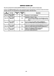
Releasing of factory TV data.
NOTE: If you can repair, examine and adjust easily. Refer to the "WHEN REPLACING EEPROM (MEMORY) IC". Power...the INITIAL DATA of the SUM DATA and MICON VERSION on the screen.
Check of MEMORY IC. DOWN (Minimum)
6
2 sec.
Display of the Adjustment MENU on the screen. SERVICE MODE LIST
This unit is provided with the following SERVICE MODES...
Service Manual - Page 14
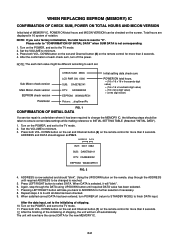
...to the TV mode. 2.
ADDRESS is undertaken where it will now have the correct DATA for more than 2 seconds. 12. After the data input, set to the initializing of notation. Turn on the screen. The ... version Main Micon check version
EEPROM check version Parameter
CHECK SUM: 3ED6 LCD PWR ON: 0000 SUB: DA0E782141 DTV: CA09E83052 EEPROM: W34N02PE01 Picture: _dispSmartPic
Initial setting data check ...
Service Manual - Page 15
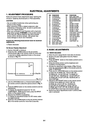
...grease may cause damages to minimum. 2. TV s.stretch 480i
Function
03 R DRIVE ...repairing the circuits or replacing electrical parts or PCB assemblies.
Adjust the LEFT/RIGHT button on the remote control.
6. To display the adjustment screen for more than 15 minutes. 2.
ELECTRICAL ADJUSTMENTS
1. Pattern Generator
On-Screen Display Adjustment
1. BASIC ADJUSTMENTS
2-1: WHITE...
Service Manual - Page 18
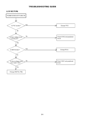
Change F401.
Check IC401 and peripheral circuit. E-1 No
Is there voltage at pin 1 of IC401 19V?
No
No Is there voltage at pin
No
10 of IC402 6V? Check IC402 and peripheral circuit. Change R412.
Yes
Yes Is R412 broken? Yes
Change DIGITAL PCB.
(LCD SECTION)
POWER DOES NOT TURN ON
TROUBLESHOOTING GUIDE
Yes Is F401 broken?
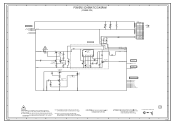
Service Manual - Page 22
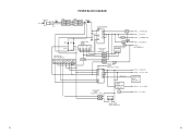
AT+5V CP401__2. POWER FAIL CP401__6.P.CON+5V CP401__3. LCD+B CP401__13. SYS_POWER_H
CP401__18.SW+12V CP406__1,2,3,4,5. +24V SOUND AMP IC302 AN17808B CP401__11,12. LCD_H
REGULATOR IC403 KIA431A-AT
F-1
F-2 POWER BLOCK DIAGRAM
CD3805 AC IN
F401 ...
Service Manual - Page 33
...
TO PANEL
IC2801
7
R8J66954BG
C2801
CP2804 A2006WR0-2X15P-HK
7
100P CH NC VDD+3.3V/NC/GND 30
VDD+3.3V/NC/GND 29
GND
28
LVDS0OUT0M E19 1.5 LVDS0OUT0P F19 1.5
NR2811 CRA108220JV
LCD_TXOUT0LCD_TXOUT0+
GND
27
RXIN0- 26
RXIN0...23
RXIN1+ 22
GND
21
RXIN2- 20
CD2804
V2301_1 V260B1-L01_M
RXIN2+ 19
CURU1704
LCD PANEL
6
GND
18
RXCLK IN- 17
RXCLK IN+ 16
PLL POWER LVDS_CH0
D1.0V...
Service Manual - Page 38
... FLASH
IIC_OFF I2C_CLK I2C_DATA
TO AV SWITCH2
ASW0
4
FROM/TO MICON I2C_CLK I2C_DATA MCU_SCIRXD MCU_SCITXD
3
FROM/TO REGULATOR2 LCD-H VDIM GND AT+3.3V D3.3V
2
PCBDH0 CEG352
1
H
H-20 A 8 7
6
5
4
3
...
R2847 10K
C2959 0.1 B
V8 3.3 SCIRXD V7 3.3 SCISCK(GPIO) W73.3
C2965 0.1 B
ASW0 ASW1 ASW2 VDIM
LCD-H
MCU_SCIRXD MCU_SCITXD
IIC_OFF
NC
4321
0 A0 0 A1 0 A2 0 Vss
Vcc WP SCL SDA
5678
3.4
0 R2856...
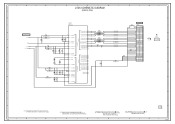
Service Manual - Page 40
...
4 AT+3.3V
5
GND
7
6 P.CON+5V
7
AT+5V
8
AT+5V
9
GND
10
GND
11 LCD+B
12 LCD+B
13 LCD_H
14 P.CON+9V
15
GND
16
GND
17 STBY_H
18 SW+12V
NC
6
19 REMOCON_IN
20 LIGHT_CTL...0.001 B R3001 100K
B
L3003 330uHNLCV32T
TUNER+30V POWER_FAIL SYS_POWER_H
AT+3.3V
D5.0V AT+5V
VDD_PANEL LCD-H
P.CON+9V
STBY-H
IR_REMO VDIM KEY_A BLON KEY_B
C3009 0.001 B
5
4
3
SH3001 SH3002 SH3003...
Service Manual - Page 41
...ONES DESCRIBED IN PARTS LIST ONLY
CAUTION: DIGITAL TRANSISTOR
F
G
2
PCB240 CEG353
1
H
H-26
THE ALUMI ELECTROLYTIC CAPACITOR MARKED NP IS NON POLAR ONE.
ATTENTION:POUR UNE PROTECTION CONTINUE LES ...YKE31-0149N
FH401 EYF-52BCY
BLACK
CP404 FH402 003P-2100
EYF-52BCY
D404_1 ENE241D-10A-Q6
1
WHITE
WHITE
7
D402
1
2
3
4
COIL,LINE FILTER L401
SS30V-R200132
SH402 YQ-12
SH410 YQ...
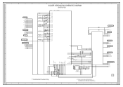
Service Manual - Page 42
...
LIGHT_CTL
VDIM
2A 125V
W814
LIGHT_POWER_H BLON SW+12V
F404 SW+12V[UNREG]
13.5
DC/DC(5V) IC IC407
LCD+B
LCD+B
20N_2000FS
12.4
LA5779
5
2A 125V
12.8
EV+17V REG
Q422
KTB1151
R491_1 330
VIN VOUT G 2.5V ON/...L404 22uH TSL0808
TO JACK2
P.CON+5V
4
FROM/TO REGULATOR
SW+12V
VDIM
BLON
3
LCD-H
LCD+B
P.CON+5V
SYS_POWER_H
P.CON+5V
AT+5V SYS_POWER_H
P_GND
2
2
1
H-27
2A ...
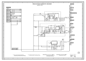
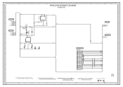
Service Manual - Page 43
...
C
D
E
F
REGULATOR SCHEMATIC DIAGRAM
8
(POWER PCB)
G
H
8
7
FROM/TO POWER2 SW+12V VDIM BLON LCD-H LCD+B
P.CON+5V SYS_POWER_H
6
FROM/TO POWER
POWER_FAIL AT+34V AT+5V
SYS_POWER_H P_GND
5
4
AT+5V
AT+34V
TU+32V...9V
GND
5
GND
4
TUNER+30V POWER_FAIL SYS_POWER_H
AT+3.3V
P.CON+5V AT+5V
P_GND
3
LCD+B LCD-H P.CON+9V
STBY-H SW+12V IR_REMO
VDIM
BLON
2
1
H-29
NOTE:THIS SCHEMATIC DIAGRAM IS...
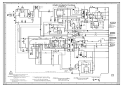
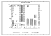
Service Manual - Page 49
...CEG353
NC
E1 CVBS_IN_1
J4206
3245
H1 H2 H3
NC
CD3805
J401
2
BLACK
1
WHITE
PC/DVI AUDIO IN J4201
567 12
34
CP401
TUNER+30V 1 1
POWER_FAIL 2...RXIN1+
22
RXIN1-
23
GND
24
RXIN0+
25
RXIN0-
26
GND
27
GND
28
VDD+3.3V/NC/GND 29 NC VDD... 6 RESET_N 7 FLASH_WP 8 ASEMD0 9 GND 10 VDD33 11 GND 12
CD2804
V2301_1 LCD PANEL
24
DIGITAL PCB PCBDH0 CEG352
SIF-out 5
AGC 7 NC V_OUT 8
+5V ...
Service Manual - Page 55
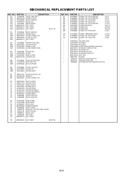
...'Y COVER LCD SPRING EARTH
107
8965TS1210 CUSHION W10/H12/L10
108
761WSA0459 SHIELD IC
109
706WPA0027 COVER CONNECTOR
110
706WPA0033 PLATE POWER
111
899RFC21V0 HOLDER CORD
112
752WSA0705 SHIELD DIGITAL
113
753WUA0063 SPRING EARTH
114
761WPAA183 HOLDER PANEL
115
761WPA0473 HOLDER SPEAKER-L
116
761WPA0474 HOLDER SPEAKER-R
117
761WPA0477 COVER HINGE
118
723000D908...
Service Manual - Page 61
SP302
070Y056007 SPEAKER 070Y056007 SPEAKER
S0412F06 S0412F06
TM101 076B0MQ051 TRANSMITTER ! V2301 09EV126010 LCD
ETR0088-010401LF V260B1-L01_M
RESISTOR RC CARBON RESISTOR
CAPACITORS CC CERAMIC CAPACITOR CE ALUMI ELECTROLYTIC CAPACITOR CP POLYESTER CAPACITOR CPP POLYPROPYLENE CAPACITOR CPL PLASTIC CAPACITOR ...
Similar Questions

How To Fix A Sharp Lcd Tv Wont Power On Model Lc 26sb14u
(Posted by lilKo 9 years ago)

White Screen On 52d824 Sharp Lcd
When turned on the TV now does not show any image, instead the screen slowly turns white andstays th...
When turned on the TV now does not show any image, instead the screen slowly turns white andstays th...
(Posted by AndreiF 12 years ago)

I Have A Common Problem With Sharp Tv's I Have A White Screen. The Caps Are O
white screen, we all know that this tv is not worth a lot of money to compensate buying a 100 plus b...
white screen, we all know that this tv is not worth a lot of money to compensate buying a 100 plus b...
(Posted by rsdecade 13 years ago)


My Sharp Lc-26sb24u Problem Audio Ok No Picture Just White Screen
(Posted by perez1802003 13 years ago)