Sharp LC-26SB14U Support Question
Sharp LC-26SB14U Support Question
Find answers below for this question about Sharp LC-26SB14U - 26" LCD TV.Need a Sharp LC-26SB14U manual? We have 1 online manual for this item!
Question posted by deo301 on November 4th, 2010
My Tv Has A White Screen
The person who posted this question about this Sharp product did not include a detailed explanation. Please use the "Request More Information" button to the right if more details would help you to answer this question.
Current Answers
Related Sharp LC-26SB14U Manual Pages
Service Manual - Page 1
... the safety and performance of the set .
" are subject to change without notice. Be sure to replace these parts with " ! SERVICE MANUAL
No.S480ILC26SB14
LCD COLOR TELEVISION
MODEL LC-26SB14U
In the interests of user-safety (Required by safety regulations in some countries) the set should be restored to its original condition and only...
Service Manual - Page 2
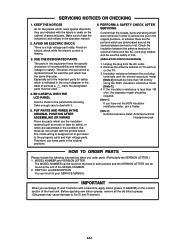
...while the electric current is indicated in the operation manual.
2. BE CAREFUL WITH THE LCD PANEL
Avoid a shock to keep the indications and notices in the circuit diagram or the ... wiring is replaced should be more than 1M ohm, the inspection repair should be found on the TV. 3. PUT PARTS AND WIRES IN THE ORIGINAL POSITION AFTER ASSEMBLING OR WIRING There are assembled in your SERVICE...
Service Manual - Page 4
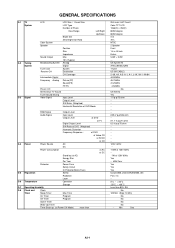
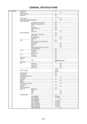
GENERAL SPECIFICATIONS
G-1 TV System
G-2 Tuning System
G-3 Signal
LCD
LCD Size / Visual Size
LCD Type
Number of Pixels
View Range
Left/Right
Up/...CH
Destination
CH Coverage
Intermediate Digital
Frequency Analog Picture(FP)
Sound(FS)
FP-FS
Preset CH
Stereo/Dual TV Sound
Tuner Sound Muting
Video Signal
Input Level
Output Level
S/N Ratio (Weighted)
Horizontal Resolution at DVD ...
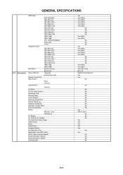
Service Manual - Page 6
... Search Power On Memory Comb Filter
Game Position
Auto Setup(Language/CH Program)
Picture Setting(TV)
AV Mode(Picture Preference)
Brightness , Contrast , Color
Tint
Sharpness
Color Temperature
DNR
Cable...Label
Favorite CH
V-Chip
Type
RRT Setup
Lock
Hotel Lock
Channel Lock
Video Lock
Panel Lock
Menu Language
Closed Caption
CC Advanced
View Mode (Picture Size)
Picture Scroll
...
Service Manual - Page 7
...
Important Safeguard
Dew/AHC Caution Sheet
Quick Set-up Sheet
Battery
UM size x pcs
OEM Brand
AC Adapter
AC Cord (for AC Adapter)
AC Cord (Flat Polarity Plugs)
Cable Cramp
Stand
Stand Screw
Hexagon Wrench
AV Cord (2Pin-1Pin)
Registration Card (NDL Card)
300 to 75ohm Antenna Adapter
Sheet Information (Return...
Service Manual - Page 8
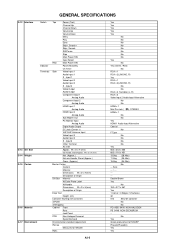
...-
Input 1
Video Input 2
Audio Input 2
S - No
Yes
Green procurement of Origin
Drop Test
Height (cm)
Container Stuffing (40' container)
w/Pallet
w/Wrapping
Cabinet Front
Rear
Jack Panel
PCB
Non-Halogen Demand
Eyelet Demand
Environmental standard requirement
Pb-free
Measures for Whisker
Rohs
Yes
Yes
Yes
Yes
Yes
No
No
No
No
No...
Service Manual - Page 9
...(1) (1) (1)
(2)
(2) (2)
(1) (1) (1)
(1)
(1)
(1) (1) (1)
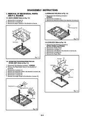
1-3 REMOCON PCB (Refer to Fig. 1-4)
1. Remove the LCD Block in the direction of arrow (A). 5.
Holder Panel
Angle Main (2)
(2) (2)
(2)
(1) Angle Main (1) (1)
LCD Block
(1)
(A)
Holder Panel
Plate Button Ass'y
(1) (1)
(1) (B)
Operation PCB (3) (2)
(3)
(3)
(A) (C)
(3) (3) (3)
Angle Hinge
Fig. 1-4
Fig. 1-2 B1...
Service Manual - Page 10
... the direction of arrow (B).
(2) (3)
(1)
(2) (4)
(5) (5)
(5)
(5) (5)
(A) Plate Jack
Shield Digital Digital PCB
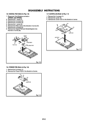
1-7: COVER LCD (Refer to Fig. 1-7)
1. Remove the screw (2). 3. Remove the 5 screws (2). 4. Remove the Cover LCD in the direction of arrow.
(2)
(1) (1)
(1) (1)
Cover LCD
LCD Panel
(B)
Fig. 1-7
Fig. 1-6
1-6: POWER PCB (Refer to Fig. 1-5)
1. Remove the 5 screws...
Service Manual - Page 11
...in the vertical direction towards the IC pattern.
DISASSEMBLY INSTRUCTIONS
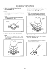
2. REMOVAL AND INSTALLATION OF FLAT PACKAGE IC
REMOVAL
1. When IC starts moving back and forth easily after desoldering the...leads completely. Peel off the Masking Tape.
5. Put Masking Tape (cotton tape) around the Flat Package IC to protect other parts from IC leads.
3. Blower type IC desoldering machine
Masking Tape...
Service Manual - Page 13
... REPLACING EEPROM (MEMORY) IC". DOWN (Minimum)
6
2 sec. Refer to the "ELECTRICAL ADJUSTMENT" (On-Screen Display Adjustment). DOWN (Minimum)
9
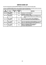
2 sec. 2 sec. SERVICE MODE LIST
This unit is provided with ...Standard Time
Operations
2 sec.
Power ON
VOL.
Power ON
VOL. C-1 Releasing of factory TV data.
NOTE: If you can repair, examine and adjust easily. Refer to the "WHEN...
Service Manual - Page 14
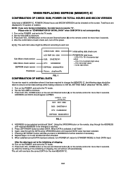
...After the confirmation of each set a factory initialization, the total hours is reset to the TV mode. 2. POWER ON total hours. = (16 x 16 x 16 x thousands digit...Micon check version
EEPROM check version Parameter
CHECK SUM: 3ED6 LCD PWR ON: 0000 SUB: DA0E782141 DTV: CA09E83052 EEPROM: ...POWER, and set and Channel button (8) on the screen. Total hours are displayed in 16 system of shipping....
Service Manual - Page 15
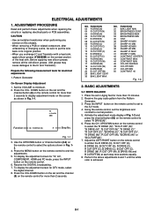
...replacing electrical parts or PCB assemblies. Pattern Generator
On-Screen Display Adjustment
1. DOWN button on the set and... button on the set in Fig. 12.
4. BASIC ADJUSTMENTS
2-1: WHITE BALANCE
1. Place the set and the channel
(9) on the remote ...channel. 8. Set the VOLUME to the IC and Transistor). Press the VOL.
TV s.stretch 480i
Function
03 R DRIVE (N)
8
Step No.
Use the UP...
Service Manual - Page 16
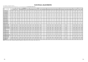
... Fixed Value (Step No.) Please check if the fixed values of each of the set correctly referring below. (TV/AV/COMPONENT/HDMI/PC/DTV)
NO. Step No. FUNCTION
AV
COMPONENT
HDMI
PC
TV
GAME
CVBS Y/C
480i/576i 480p/576p 720p 1080i 480i/576i 480p/576p 720p 1080i VGA 640x480 1280x720 640*480...
Service Manual - Page 18
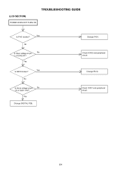
Yes
Yes Is R412 broken? No
Is there voltage at pin 1 of IC401 19V?
Change R412. (LCD SECTION)
POWER DOES NOT TURN ON
TROUBLESHOOTING GUIDE
Yes Is F401 broken?
E-1 Yes
Change DIGITAL PCB. Check IC401 and peripheral circuit.
Change F401.
No
No Is there voltage at pin
No
10 of IC402 6V? Check IC402 and peripheral circuit.
Service Manual - Page 20
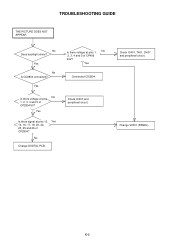
Check IC407 and peripheral circuit.
Change V2301 (PANEL).
Yes
Is there signal at pins 13, Yes 14, 16, 17, 19, 20, 22, 23, 25 and 26 of CP406 24V? Check IC401, T401, D437 and peripheral circuit. TROUBLESHOOTING GUIDE
THE PICTURE DOES NOT APPEAR
No Does backlight shine?
No
Change DIGITAL PCB.
E-3 ...
Service Manual - Page 22
...-1-V(W)
8
10
7
13
5
14
15
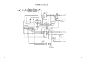
SOUND +B
2
1 IC407 DC/DC(5V) LA5779-E
FEED BACK
IC408
SW
PS2561AL1-1-V(W)
41 32
31
CP401__1.TUNER+30V CP401__7.8. AT+5V CP401__2. LCD+B CP401__13. LCD_H
REGULATOR IC403 KIA431A-AT
F-1
F-2 POWER FAIL CP401__6.P.CON+5V CP401__3.
Service Manual - Page 33
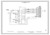
.../GND 29
GND
28
LVDS0OUT0M E19 1.5 LVDS0OUT0P F19 1.5
NR2811 CRA108220JV
LCD_TXOUT0LCD_TXOUT0+
GND
27
RXIN0- 26
RXIN0+ 25
FROM REGULATOR2
B2806
HCB1608KF-221T20
D3.3V
B2807
HCB1608KF-221T20
6
C2865 10V 22 V-S... 23
RXIN1+ 22
GND
21
RXIN2- 20
CD2804
V2301_1 V260B1-L01_M
RXIN2+ 19
CURU1704
LCD PANEL
6
GND
18
RXCLK IN- 17
RXCLK IN+ 16
PLL POWER LVDS_CH0
D1.0V VDD_PANEL
...
Service Manual - Page 41
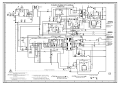
...YKE31-0149N
FH401 EYF-52BCY
BLACK
CP404 FH402 003P-2100
EYF-52BCY
D404_1 ENE241D-10A-Q6
1
WHITE
WHITE
7
D402
1
2
3
4
COIL,LINE FILTER L401
SS30V-R200132
SH402 YQ-12
SH410 YQ... FOR SAFETY,USE ONES DESCRIBED IN PARTS LIST ONLY
CAUTION: DIGITAL TRANSISTOR
F
G
2
PCB240 CEG353
1
H
H-26 A
B
H-25
R448 39K +-1%
R449 6.8K +-1%
R467 75K +-1%
CAUTION: IS THE LIVE CONNECTION
34 21...
Service Manual - Page 49
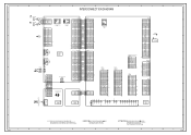
...CEG353
NC
E1 CVBS_IN_1
J4206
3245
H1 H2 H3
NC
CD3805
J401
2
BLACK
1
WHITE
PC/DVI AUDIO IN J4201
567 12
34
CP401
TUNER+30V 1 1
POWER_FAIL 2...RXIN1+
22
RXIN1-
23
GND
24
RXIN0+
25
RXIN0-
26
GND
27
GND
28
VDD+3.3V/NC/GND 29 NC VDD... 6 RESET_N 7 FLASH_WP 8 ASEMD0 9 GND 10 VDD33 11 GND 12
CD2804
V2301_1 LCD PANEL
24
DIGITAL PCB PCBDH0 CEG352
SIF-out 5
AGC 7 NC V_OUT 8
+5V ...
Service Manual - Page 55
...'Y COVER LCD SPRING EARTH
107
8965TS1210 CUSHION W10/H12/L10
108
761WSA0459 SHIELD IC
109
706WPA0027 COVER CONNECTOR
110
706WPA0033 PLATE POWER
111
899RFC21V0 HOLDER CORD
112
752WSA0705 SHIELD DIGITAL
113
753WUA0063 SPRING EARTH
114
761WPAA183 HOLDER PANEL
115
761WPA0473 HOLDER SPEAKER-L
116
761WPA0474 HOLDER SPEAKER-R
117
761WPA0477 COVER HINGE
118
723000D908...
Similar Questions

How Do I Get The Power On For A Sharp Tv Flat Screen
(Posted by gmakr 10 years ago)

White Screen Problem With Lcd Tv Lc26sb14u
How to troubleshoot and repair ?
How to troubleshoot and repair ?
(Posted by thl748 11 years ago)

What To Do When Screen Is All White
(Posted by ladeannalloyd 12 years ago)

White Screen On 52d824 Sharp Lcd
When turned on the TV now does not show any image, instead the screen slowly turns white andstays th...
When turned on the TV now does not show any image, instead the screen slowly turns white andstays th...
(Posted by AndreiF 12 years ago)
I Have A Common Problem With Sharp Tv's I Have A White Screen. The Caps Are O
white screen, we all know that this tv is not worth a lot of money to compensate buying a 100 plus b...
white screen, we all know that this tv is not worth a lot of money to compensate buying a 100 plus b...
(Posted by rsdecade 13 years ago)