

Service Manual
Page 16
.... Also, do not attempt these adjustments unless the proper equipment is important to enter the service mode: Press [MENU] and [POWER] buttons on table 1. Remote control unit 4. Initial Setting General : Enter service mode. Set initial data as shown on the TV unit simultaneously in the standby mode. 1. ITEM NOTE: ... Data ITEM RF-BRT RF-CNT RF-CLR-R RF-CLR-B RF-TNT RF-SHR V-BRT V-CNT V-CLR-R V-CLR-B V-TNT V-SHR BUTTON (on the DATA VALUE remote control) 122 200 130 [MENU] [1] 115 135 112 123 182 110 [MENU] [2] 110 138 112 S-BRT S-CNT S-CLR-R S-CLR-B S-TNT S-SHR D1-BRT ...
.... Also, do not attempt these adjustments unless the proper equipment is important to enter the service mode: Press [MENU] and [POWER] buttons on table 1. Remote control unit 4. Initial Setting General : Enter service mode. Set initial data as shown on the TV unit simultaneously in the standby mode. 1. ITEM NOTE: ... Data ITEM RF-BRT RF-CNT RF-CLR-R RF-CLR-B RF-TNT RF-SHR V-BRT V-CNT V-CLR-R V-CLR-B V-TNT V-SHR BUTTON (on the DATA VALUE remote control) 122 200 130 [MENU] [1] 115 135 112 123 182 110 [MENU] [2] 110 138 112 S-BRT S-CNT S-CLR-R S-CLR-B S-TNT S-SHR D1-BRT ...

Service Manual
Page 17
...20 minutes. 2. Refer to 0.291) Figure It carries out in the field. Turn the power off and on again. (Main power button on the remote control unit and select "C/D2" mode. 5. [RF/INPUT1]----(APL80%) Press [6] button to select "DB(C/D1)" for Red adjustment.When "x" value and ... to 0.283) y (0.281 to "1. When "x" value and "y" value are not within specification, adjust "C-DB(C/D2)" or "CDR(C/D2)". Press [VOL -] button on the remote control unit. (selecting "BRT" mode). 5-2 A7121EA Refer to "1. EQ. [RF/INPUT1] C/D1 [INPUT2] C/D2 White Purity (APL 80%) or (APL 20%) Spec. ...
...20 minutes. 2. Refer to 0.291) Figure It carries out in the field. Turn the power off and on again. (Main power button on the remote control unit and select "C/D2" mode. 5. [RF/INPUT1]----(APL80%) Press [6] button to select "DB(C/D1)" for Red adjustment.When "x" value and ... to 0.283) y (0.281 to "1. When "x" value and "y" value are not within specification, adjust "C-DB(C/D2)" or "CDR(C/D2)". Press [VOL -] button on the remote control unit. (selecting "BRT" mode). 5-2 A7121EA Refer to "1. EQ. [RF/INPUT1] C/D1 [INPUT2] C/D2 White Purity (APL 80%) or (APL 20%) Spec. ...
Service Manual
Page 18
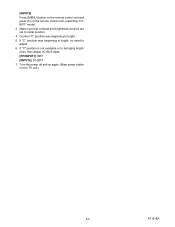
If "C" position was beginning to be highly brightness, then adjust IIC-BUS dada. [RF/INPUT1]: BRT [INPUT2]: D1-BRT 7. [INPUT2] Press [MENU] button on the remote control unit and press [3] on the TV unit.) 5-3 A7121EA Make sure that contrast and brightness controls are set to adjust. 6. If "C" position is not available or to bright. 5. Turn the power off and on again. (Main power button on the remote control unit. (selecting "D1BRT" mode). 3. Confirm "C" position was beginning to bright, no need to initial position. 4.
If "C" position was beginning to be highly brightness, then adjust IIC-BUS dada. [RF/INPUT1]: BRT [INPUT2]: D1-BRT 7. [INPUT2] Press [MENU] button on the remote control unit and press [3] on the TV unit.) 5-3 A7121EA Make sure that contrast and brightness controls are set to adjust. 6. If "C" position is not available or to bright. 5. Turn the power off and on again. (Main power button on the remote control unit. (selecting "D1BRT" mode). 3. Confirm "C" position was beginning to bright, no need to initial position. 4.

Service Manual
Page 19
HOW TO INITIALIZE THE LCD TELEVISION 1. Confirm "FF" indication on the remote control unit. 3. To initialize the LCD television, press [DISPLAY] button on the upper right of the screen. 6-1 A7121INT To enter the service mode, press [MENU] and [POWER] buttons on the TV unit simultaneously in the standby mode. 2.
HOW TO INITIALIZE THE LCD TELEVISION 1. Confirm "FF" indication on the remote control unit. 3. To initialize the LCD television, press [DISPLAY] button on the upper right of the screen. 6-1 A7121INT To enter the service mode, press [MENU] and [POWER] buttons on the TV unit simultaneously in the standby mode. 2.

Service Manual
Page 20
...+9V is not output. 7-5 18 DTV-ON+1.8V is not output. 7-5 19 The key operation is not functioning. 7-6 20 No operation is possible from the remote control unit. 7-6 21 Picture does not appear normally. (Tuner input (Analog) / Video input/S-Video input) 7-7 22 Picture does not appear normally. (Tuner input (Digital)) 7-7 23...
...+9V is not output. 7-5 18 DTV-ON+1.8V is not output. 7-5 19 The key operation is not functioning. 7-6 20 No operation is possible from the remote control unit. 7-6 21 Picture does not appear normally. (Tuner input (Analog) / Video input/S-Video input) 7-7 22 Picture does not appear normally. (Tuner input (Digital)) 7-7 23...
Service Manual
Page 25
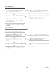
...pulse sent out Pin(1) terminal of CN102A (shown below) increase? Check AL+3.3V(D) line and service it if defective. Replace the infrared remote control receiver (RCV1142) or the remote control unit. SW1101,1102,1103,1104,1105,1107 : CN1301 PIN 2 SW1111 : CN1301 PIN 1 Yes Check IC1202 and the periphery circuit,...No Yes Check IC1202 and the periphery circuit, and service it if defective. FLOW CHART NO.19 The key operation is possible from the remote control unit. No Are the contact point and installation state of CN1302 , and service it if defective. 7-6 A7121TS FLOW CHART NO.20 ...
...pulse sent out Pin(1) terminal of CN102A (shown below) increase? Check AL+3.3V(D) line and service it if defective. Replace the infrared remote control receiver (RCV1142) or the remote control unit. SW1101,1102,1103,1104,1105,1107 : CN1301 PIN 2 SW1111 : CN1301 PIN 1 Yes Check IC1202 and the periphery circuit,...No Yes Check IC1202 and the periphery circuit, and service it if defective. FLOW CHART NO.19 The key operation is possible from the remote control unit. No Are the contact point and installation state of CN1302 , and service it if defective. 7-6 A7121TS FLOW CHART NO.20 ...

Service Manual
Page 29
A7121BLS 8-1 NOTE: CBA AND PWB MEANS PRINTED WIRING BOARD. IC1202 (TV MICRO CONTROLLER) KEY-IN-2 4 KEY-IN-1 3 REMOTE 27 RESET 94 XIN 37 XOUT 38 Q917 RESET AL+3.3V(D) X1301 27MHz DTV-ON-H 152 BACKLIGHT-SW 157 P-ON-H 28 BACKLIGHT-ADJ 20 IF-... (MEMORY) 7 WP 5 SDA 6 SCL IC61 (MEMORY) 5 SDA 6 SCL MAIN CBA CN1301 1 KEY-IN-2 2 KEY-IN-1 CL1107 1 2 KEY SWITCH KEY SWITCH FUNCTION CBA CN1302 3 REMOTE 4 P-ON-H CL1104 3 4 RV1142 REMOTE SENSOR Q1142 LED DRIVE D1142 POWER AL+3.3V(D) IR SENSOR CBA DTV-ON-H BACKLIGHT-SW P-ON-H BACKLIGHT-ADJ TO POWER SUPPLY BLOCK DIAGRAM TO...
A7121BLS 8-1 NOTE: CBA AND PWB MEANS PRINTED WIRING BOARD. IC1202 (TV MICRO CONTROLLER) KEY-IN-2 4 KEY-IN-1 3 REMOTE 27 RESET 94 XIN 37 XOUT 38 Q917 RESET AL+3.3V(D) X1301 27MHz DTV-ON-H 152 BACKLIGHT-SW 157 P-ON-H 28 BACKLIGHT-ADJ 20 IF-... (MEMORY) 7 WP 5 SDA 6 SCL IC61 (MEMORY) 5 SDA 6 SCL MAIN CBA CN1301 1 KEY-IN-2 2 KEY-IN-1 CL1107 1 2 KEY SWITCH KEY SWITCH FUNCTION CBA CN1302 3 REMOTE 4 P-ON-H CL1104 3 4 RV1142 REMOTE SENSOR Q1142 LED DRIVE D1142 POWER AL+3.3V(D) IR SENSOR CBA DTV-ON-H BACKLIGHT-SW P-ON-H BACKLIGHT-ADJ TO POWER SUPPLY BLOCK DIAGRAM TO...
Service Manual
Page 52
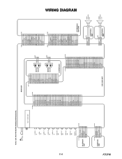
...-Y IN VIDEO-Pb IN VIDEO-Pr IN AUDIO(R) -IN1 AUDIO(L) -IN1 AUDIO(R) -IN2 AUDIO(L) -IN2 DIGITAL AUDIO-OUT CL1104 1 2 IR SENSOR 3 CBA 4 5 AL+3.3V(D) GND REMOTE P-ON-H NU CN1302 1 2 3 4 5 CN1201 1 2 3 4 5 6 7 8 9 10 11 12 13 14 15 16 17 18 19 20 21 22 23 24 25 26 27 28 29 30...
...-Y IN VIDEO-Pb IN VIDEO-Pr IN AUDIO(R) -IN1 AUDIO(L) -IN1 AUDIO(R) -IN2 AUDIO(L) -IN2 DIGITAL AUDIO-OUT CL1104 1 2 IR SENSOR 3 CBA 4 5 AL+3.3V(D) GND REMOTE P-ON-H NU CN1302 1 2 3 4 5 CN1201 1 2 3 4 5 6 7 8 9 10 11 12 13 14 15 16 17 18 19 20 21 22 23 24 25 26 27 28 29 30...
Service Manual
Page 53
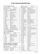
... On Signal 2 at High 23 VOLUME Volume Control Signal Output 24 VDD+1.2V +1.2V VDD 25 VDD+1.2V +1.2V VDD 26 NU Not Used 27 REMOTE Remote Control Signal Input 28 P-ON-H Power On Signal at High 29 BUS-OPEN Chip select 30 SCL Serial Clock 31 SDA Serial Data 32 NU...
... On Signal 2 at High 23 VOLUME Volume Control Signal Output 24 VDD+1.2V +1.2V VDD 25 VDD+1.2V +1.2V VDD 26 NU Not Used 27 REMOTE Remote Control Signal Input 28 P-ON-H Power On Signal at High 29 BUS-OPEN Chip select 30 SCL Serial Clock 31 SDA Serial Data 32 NU...
Service Manual
Page 72
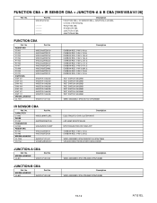
... 333HT/F45-50K NPN TRANSISTOR KRC103M-AT/P CARBON RES. 1/4W J 120 Ω CARBON RES. 1/4W J 330 Ω WIRE ASSEMBLY 5PIN SENSOR 15V 5PIN/70MM SENSOR REMOTE RECEIVER KSM-603SR2E JUNCTION-A CBA Ref. No.
... 333HT/F45-50K NPN TRANSISTOR KRC103M-AT/P CARBON RES. 1/4W J 120 Ω CARBON RES. 1/4W J 330 Ω WIRE ASSEMBLY 5PIN SENSOR 15V 5PIN/70MM SENSOR REMOTE RECEIVER KSM-603SR2E JUNCTION-A CBA Ref. No.


