
Service Manual
Page 1
... SCHEMATIC DIAGRAM ...14 VOLTAGE ...31 WIRING SIDE OF P.W.BOARD ...32 FUNCTION TABLE OF IC ...38 FL DISPLAY ...44 REPLACEMENT PARTS LIST/EXPLODED VIEW PACKING OF THE SET (FOR U.S.A. ONLY) SHARP CORPORATION This document has been published to those specified be used . CONTENTS Page IMPORTANT SERVICE NOTES (FOR U.S.A. The contents are subject to change without notice. S7250HTCN300/ HOME CINEMA COMMAND MODEL HT-CN300(S) HT-CN300 Home Cinema Command consisting of user...
... SCHEMATIC DIAGRAM ...14 VOLTAGE ...31 WIRING SIDE OF P.W.BOARD ...32 FUNCTION TABLE OF IC ...38 FL DISPLAY ...44 REPLACEMENT PARTS LIST/EXPLODED VIEW PACKING OF THE SET (FOR U.S.A. ONLY) SHARP CORPORATION This document has been published to those specified be used . CONTENTS Page IMPORTANT SERVICE NOTES (FOR U.S.A. The contents are subject to change without notice. S7250HTCN300/ HOME CINEMA COMMAND MODEL HT-CN300(S) HT-CN300 Home Cinema Command consisting of user...
Service Manual
Page 2
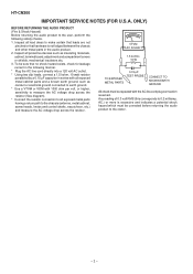
... protective devices such as conduit or electrical ground connected to earth ground. * Use a VTVM or VOM with 1000 ohm per volt, or higher, sensitivity to all exposed metal cabinet parts and a known earth ground, such as insulating materials, cabinet, terminal board, adjustment ... metal parts in series with the AC line cord plug connection reversed. HT-CN300 IMPORTANT SERVICE NOTES (FOR U.S.A. Inspect all lead dress to the user, perform the following manner. * Plug the AC line cord directly into a 120 volt AC outlet. * Using two clip leads, connect a 1.5 kohm, 10 watt resistor paralleled...
... protective devices such as conduit or electrical ground connected to earth ground. * Use a VTVM or VOM with 1000 ohm per volt, or higher, sensitivity to all exposed metal cabinet parts and a known earth ground, such as insulating materials, cabinet, terminal board, adjustment ... metal parts in series with the AC line cord plug connection reversed. HT-CN300 IMPORTANT SERVICE NOTES (FOR U.S.A. Inspect all lead dress to the user, perform the following manner. * Plug the AC line cord directly into a 120 volt AC outlet. * Using two clip leads, connect a 1.5 kohm, 10 watt resistor paralleled...
Service Manual
Page 3
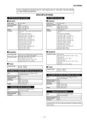
... RCA type Audio input (Video 1): RCA type (L/R) Audio input (Auxiliary): RCA type (L/R) Video input (Video 2): RCA type S-video input (DVD): S-terminal Video input (DVD): RCA type Audio input (Video 2): RCA type (L/R) Digital input (DVD): Optical Digital input (DVD): Coaxial Amplifier Power output (FTC) Rated power output 30 watts minimum RMS per channel into 6 ohms from 200 Hz to 20 kHz, 10 % total harmonic distortion Front: 30 W + 30 W (10% T.H.D, 1 kHz) Center: 30 W (10% T.H.D, 1 kHz) Surround: 30 W + 30 W (10% T.H.D, 1 kHz) Subwoofer: 30 W (10% T.H.D, 100 Hz) Tuner Frequency range FM...
... RCA type Audio input (Video 1): RCA type (L/R) Audio input (Auxiliary): RCA type (L/R) Video input (Video 2): RCA type S-video input (DVD): S-terminal Video input (DVD): RCA type Audio input (Video 2): RCA type (L/R) Digital input (DVD): Optical Digital input (DVD): Coaxial Amplifier Power output (FTC) Rated power output 30 watts minimum RMS per channel into 6 ohms from 200 Hz to 20 kHz, 10 % total harmonic distortion Front: 30 W + 30 W (10% T.H.D, 1 kHz) Center: 30 W (10% T.H.D, 1 kHz) Surround: 30 W + 30 W (10% T.H.D, 1 kHz) Subwoofer: 30 W (10% T.H.D, 100 Hz) Tuner Frequency range FM...
Service Manual
Page 4
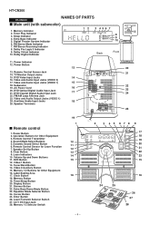
... Select Button 6. Clear Button 9. Video-2/Auxiliary Button 15. Timer Play Indicator 3. FM Stereo Receiving Indicator 8. Subwoofer 19. DVD Optical Digital Audio Input Jack 21. Memory Button 19. Display Button 21. Extra Bass Indicator 5. AC Power Cord 16 20. FM/AM Loop Antenna Jack 23. Sound Mode Select Buttons 5. DVD Button 12. Power Button 13 13. Speaker Terminals 11 12 20 21 22 23 24 25 Remote control 1. Volume Up and Down Buttons 11. Memory 1/2 Buttons for Other Equipment 16. Extra Bass/Demo Mode Button 23. Enter Button 26. HT-CN300 HT...
... Select Button 6. Clear Button 9. Video-2/Auxiliary Button 15. Timer Play Indicator 3. FM Stereo Receiving Indicator 8. Subwoofer 19. DVD Optical Digital Audio Input Jack 21. Memory Button 19. Display Button 21. Extra Bass Indicator 5. AC Power Cord 16 20. FM/AM Loop Antenna Jack 23. Sound Mode Select Buttons 5. DVD Button 12. Power Button 13 13. Speaker Terminals 11 12 20 21 22 23 24 25 Remote control 1. Volume Up and Down Buttons 11. Memory 1/2 Buttons for Other Equipment 16. Extra Bass/Demo Mode Button 23. Enter Button 26. HT-CN300 HT...

Service Manual
Page 5
.... Full-Range Speaker 2. Mounting Slot 5. Front 1 HT-CN300 3 Side 2 3 Bottom 5 4 6 - 5 - Remote Sensor 2. Remote Sensor Connection Plug Double-sided tape for remote control sensor: 1 You can fix the remote control sensor with the supplied tape. 2 Caution: Carefully choose where you place the remote control sensor as the tape adhesive may fall. Speaker Terminals 6. Remote Control Indicator 3. Angle Adjusting Lever 3. Label indication Front Speaker (right): Red Front Speaker (left): White Center Speaker: Green Surround Speaker (right): Gray Surround Speaker (left...
.... Full-Range Speaker 2. Mounting Slot 5. Front 1 HT-CN300 3 Side 2 3 Bottom 5 4 6 - 5 - Remote Sensor 2. Remote Sensor Connection Plug Double-sided tape for remote control sensor: 1 You can fix the remote control sensor with the supplied tape. 2 Caution: Carefully choose where you place the remote control sensor as the tape adhesive may fall. Speaker Terminals 6. Remote Control Indicator 3. Angle Adjusting Lever 3. Label indication Front Speaker (right): Red Front Speaker (left): White Center Speaker: Green Surround Speaker (right): Gray Surround Speaker (left...
Service Manual
Page 6
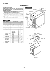
... LCD Cover 1. Screw D1) x25 6-1, 7-1 Rear Panel 5 DSP PWB 1. Flat Cable E3) x4 4. Screw F1) x4 7-2 PWB Unit 2. Socket J2) x4 10 Speaker PWB 1. Flat Cable C2) x3 3. Screw G1) x3 7-3 ...Video PWB 1. PWB 1. Screw K1) x1 7-3 11 Subwoofer 1. Hexagon Screw ...... (B1) x2 6-1 3 Top Cover A/ LCD PWB 1. Screw C3) x4 4 Back Cover L/R/ 1. Socket E2) x1 3. Screw J1) x6 7-3 2. After servicing the unit, be removed when disassembling the unit. Screw C1) x4 6-2 2. Screw E1) x2 7-2 2. Screw H1) x2 7-3 9 AMP. Socket G2) x2 8 Audio PWB 1. HT...
... LCD Cover 1. Screw D1) x25 6-1, 7-1 Rear Panel 5 DSP PWB 1. Flat Cable E3) x4 4. Screw F1) x4 7-2 PWB Unit 2. Socket J2) x4 10 Speaker PWB 1. Flat Cable C2) x3 3. Screw G1) x3 7-3 ...Video PWB 1. PWB 1. Screw K1) x1 7-3 11 Subwoofer 1. Hexagon Screw ...... (B1) x2 6-1 3 Top Cover A/ LCD PWB 1. Screw C3) x4 4 Back Cover L/R/ 1. Socket E2) x1 3. Screw J1) x6 7-3 2. After servicing the unit, be removed when disassembling the unit. Screw C1) x4 6-2 2. Screw E1) x2 7-2 2. Screw H1) x2 7-3 9 AMP. Socket G2) x2 8 Audio PWB 1. HT...

Service Manual
Page 7
... Remote control sensoe is available in assembles only and may not be disassembled. - 7 - PWB (J2)x1 (K1)x1 ø3x8mm (J1)x6 ø3x8mm AMP. Subwoofer Box DSP PWB Rear Panel (G1)x3 ø3x8mm HT-CN300 (G2)x1 Tuner PWB Video PWB (J2)x1 Tuner PWB (D1)x19 ø3x8mm Figure 7-1 (H1)x2 ø3x8mm (G2)x1 Audio PWB (J2)x2 Speaker...
... Remote control sensoe is available in assembles only and may not be disassembled. - 7 - PWB (J2)x1 (K1)x1 ø3x8mm (J1)x6 ø3x8mm AMP. Subwoofer Box DSP PWB Rear Panel (G1)x3 ø3x8mm HT-CN300 (G2)x1 Tuner PWB Video PWB (J2)x1 Tuner PWB (D1)x19 ø3x8mm Figure 7-1 (H1)x2 ø3x8mm (G2)x1 Audio PWB (J2)x2 Speaker...
Service Manual
Page 8
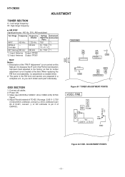
... IF VR351 T351 FM MUTE LEVEL OSD SECTION 1: Connect all cables. 2: Power ON 3: Video input (DVD IN or VIDEO 1-IN or VIDEO 2-IN) :NTSC Signal. 4: Adjust Vfc with DC voltmeter, connect (+) of DC voltmeter to pin 26 of IC401, connect (-) of DC voltmeter to pin 2 of the "FM IF Adjustment" is needed at the field. HT-CN300 ADJUSTMENT TUNER SECTION fL: Low-range frequency fH: High-range frequency • AM IF/RF...
... IF VR351 T351 FM MUTE LEVEL OSD SECTION 1: Connect all cables. 2: Power ON 3: Video input (DVD IN or VIDEO 1-IN or VIDEO 2-IN) :NTSC Signal. 4: Adjust Vfc with DC voltmeter, connect (+) of DC voltmeter to pin 26 of IC401, connect (-) of DC voltmeter to pin 2 of the "FM IF Adjustment" is needed at the field. HT-CN300 ADJUSTMENT TUNER SECTION fL: Low-range frequency fH: High-range frequency • AM IF/RF...
Service Manual
Page 9
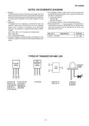
... 333ID213 EL204GT EL204HT - 9 - In the power section, a tape is being played back. • Parts marked with " 1 " ( ) are important for maintaining the safety and performance of the set . In the tuner section, indicates AM indicates FM stereo 2. REF. Be sure to change for improvement without any symbol is ohm-type resistor. HT-CN300 NOTES ON SCHEMATIC DIAGRAM • Resistor: To differentiate the units...
... 333ID213 EL204GT EL204HT - 9 - In the power section, a tape is being played back. • Parts marked with " 1 " ( ) are important for maintaining the safety and performance of the set . In the tuner section, indicates AM indicates FM stereo 2. REF. Be sure to change for improvement without any symbol is ohm-type resistor. HT-CN300 NOTES ON SCHEMATIC DIAGRAM • Resistor: To differentiate the units...

Service Manual
Page 11
...POWER AMP 8 LM4766 1 3 4 W 15 2 IC10 REMOTE SENSOR 1 2 3 SW678 +B7 RY250 +B2 SUBWOOFER J201 CENTER 20ATT Q210 Q220 20ATT Q240 Q230 10 5 L IC202 13 8 POWER LM4766 AMP 1 3 4 R 2 15 RY230 +B2 10 5 IC201 L 13 POWER AMP 1 8 LM4766 3 4 R 2 15 RY210 +B2 -B1 D101 +B1 F101 8A/125V T100 MAIN POWER TRANSFORMER SURROUND MAIN SPEAKER TERMINAL +B6 Q202 FAN MOTOR DRIVER...F511 4A/125V L511 LINE FILTER AC POWER SUPPLY CORD AC 120 V/60 Hz IC501 KTA7805AP1 CONSTANT VOLTAGE REGULATOR D522 D523 D524 D525 T501 SUB POWER TRANSFORMER Figure 11 BLOCK DIAGRAM (2/4) - 11 -
...POWER AMP 8 LM4766 1 3 4 W 15 2 IC10 REMOTE SENSOR 1 2 3 SW678 +B7 RY250 +B2 SUBWOOFER J201 CENTER 20ATT Q210 Q220 20ATT Q240 Q230 10 5 L IC202 13 8 POWER LM4766 AMP 1 3 4 R 2 15 RY230 +B2 10 5 IC201 L 13 POWER AMP 1 8 LM4766 3 4 R 2 15 RY210 +B2 -B1 D101 +B1 F101 8A/125V T100 MAIN POWER TRANSFORMER SURROUND MAIN SPEAKER TERMINAL +B6 Q202 FAN MOTOR DRIVER...F511 4A/125V L511 LINE FILTER AC POWER SUPPLY CORD AC 120 V/60 Hz IC501 KTA7805AP1 CONSTANT VOLTAGE REGULATOR D522 D523 D524 D525 T501 SUB POWER TRANSFORMER Figure 11 BLOCK DIAGRAM (2/4) - 11 -

Service Manual
Page 12
HT... 14 8 D6 O6 13 9 D7 O7 12 10 GND CK 11 IC709 GP1F32R DIGITAL IN VCC 1 GND 2 VOUT 3 +5V +B4A IC721 TC7WU04U INVERTER CON707 SPDIF ...15 D2 16 D1 17 D0 4 RD 21 EXTMEM IC706 CS493292 DSP XMT958 3 MCLK 44 SCLK 43 LRCLK 42 AUDAT0 41 AUDAT1 ...RESET SCDOUT CS INTREQ SCDIN VD1 VD2 VD3 DGND1 DGND2 DGND3 AGND 36 18 19 20 6 1 12 23 2 13 24 35 1 +B5B +2V5 IC704 74HC07AF BUFFER AMP. 2 3 6 9 10 12 VCC 14 GND 7 IC707 TC7WU04U DUAL2-INPUT... SDA 30 F_SP_RLY 82 C_SP_RLY 81 S_SP_RLY 80 W_SP_RLY 79 S_MUTE POWER DPL_LED AAC_LED VIR_LED DTS_LED STD_LED DD_LED RXIN FLD_RESET FLD_CS FLD_SCK FLD_SDATA ...
HT... 14 8 D6 O6 13 9 D7 O7 12 10 GND CK 11 IC709 GP1F32R DIGITAL IN VCC 1 GND 2 VOUT 3 +5V +B4A IC721 TC7WU04U INVERTER CON707 SPDIF ...15 D2 16 D1 17 D0 4 RD 21 EXTMEM IC706 CS493292 DSP XMT958 3 MCLK 44 SCLK 43 LRCLK 42 AUDAT0 41 AUDAT1 ...RESET SCDOUT CS INTREQ SCDIN VD1 VD2 VD3 DGND1 DGND2 DGND3 AGND 36 18 19 20 6 1 12 23 2 13 24 35 1 +B5B +2V5 IC704 74HC07AF BUFFER AMP. 2 3 6 9 10 12 VCC 14 GND 7 IC707 TC7WU04U DUAL2-INPUT... SDA 30 F_SP_RLY 82 C_SP_RLY 81 S_SP_RLY 80 W_SP_RLY 79 S_MUTE POWER DPL_LED AAC_LED VIR_LED DTS_LED STD_LED DD_LED RXIN FLD_RESET FLD_CS FLD_SCK FLD_SDATA ...

Service Manual
Page 38
... 14 15 Figure 38 BLOCK DIAGRAM OF IC - 38 - FC AFC control voltage input. SYNC IN Video signal input in the built-in the crystal oscillator for an internal sync signal. SECMA SECAM mode switching at input. 526/625 Scan line switching (525/625) at input. CV OUT Composite video signal output. SYNC DET EX-NOR output by horizontal sync signals (AFC) and CSYNC (sync separation). HT-CN300 FUNCTION TABLE OF IC IC401 VHiLC74763...
... 14 15 Figure 38 BLOCK DIAGRAM OF IC - 38 - FC AFC control voltage input. SYNC IN Video signal input in the built-in the crystal oscillator for an internal sync signal. SECMA SECAM mode switching at input. 526/625 Scan line switching (525/625) at input. CV OUT Composite video signal output. SYNC DET EX-NOR output by horizontal sync signals (AFC) and CSYNC (sync separation). HT-CN300 FUNCTION TABLE OF IC IC401 VHiLC74763...

Service Manual
Page 39
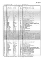
... control. 45 P70 DSP RESET Output DSP Microcomputer reset. 46 VDD VDD Input (+) Power supply. 47 P127 DSP SMUTE IN Input DSP S-mute Signal input . 48 P126 49 P125 DSP POWER IN DD LED Input Input DSP power on signal input. Power output level input 27 ANI6 PROTECT Input Protect input. 28 ANI5 THERMO Input Thermo level input. 29 ANI4 TUN SM Input Tuner signal meter. 30 ANI3 DIST 1 Input Distination 1. 31 32-33 ANI2 ANI1-ANI0 DIST 0 KEY 1-KEY 0 Input Input Distination 0. DSP DTS LED input. 52 P122 VIR LED Input DSP...
... control. 45 P70 DSP RESET Output DSP Microcomputer reset. 46 VDD VDD Input (+) Power supply. 47 P127 DSP SMUTE IN Input DSP S-mute Signal input . 48 P126 49 P125 DSP POWER IN DD LED Input Input DSP power on signal input. Power output level input 27 ANI6 PROTECT Input Protect input. 28 ANI5 THERMO Input Thermo level input. 29 ANI4 TUN SM Input Tuner signal meter. 30 ANI3 DIST 1 Input Distination 1. 31 32-33 ANI2 ANI1-ANI0 DIST 0 KEY 1-KEY 0 Input Input Distination 0. DSP DTS LED input. 52 P122 VIR LED Input DSP...

Service Manual
Page 40
... sw input. 59 P113 V SW 2 Output Video select sw 2. 60 P112 V SW 1 Output Video select sw 1. 61 P111 V REC MUTE Output Video REC mute. 62 P110 FUNC_DVD Output Function DVD : H, other :L. 63* P107 FUNC_TUNER Output Function tuner : H, other : L. 64 P106 NO USE Output GND. 65* P105 LMUTE Output Line out mute control. 66 P104 AC RLY Output AC RLY control. 67 P103 W SP RLY Output Subwoofer rely control. 68 P102 S SP RLY Output Surround speaker rely control. 69...
... sw input. 59 P113 V SW 2 Output Video select sw 2. 60 P112 V SW 1 Output Video select sw 1. 61 P111 V REC MUTE Output Video REC mute. 62 P110 FUNC_DVD Output Function DVD : H, other :L. 63* P107 FUNC_TUNER Output Function tuner : H, other : L. 64 P106 NO USE Output GND. 65* P105 LMUTE Output Line out mute control. 66 P104 AC RLY Output AC RLY control. 67 P103 W SP RLY Output Subwoofer rely control. 68 P102 S SP RLY Output Surround speaker rely control. 69...
Service Manual
Page 41
... L-MUTE Output Output DSP IC RESET output. Audition model select input. 43* P53/BCLK F_CONT Output Switches power supply frequency and changes oscillation frequency. 44* P52/RD FM_STB Output When function is not connected to VCC via pull-down resistance. Active "L". "L" fixed. 20 P82/INT0 21* P81/TA4IN/U RX_IN TIMER_LED Input Output Sharp method, remote control input.. Input Connected to unused external bus. 9 CNVSS FLASH_VCC Input Used in the single chip mode. Surround mode stanrd IND. 24 P76/TA3OUT DTS_LED Output DTS IND...
... L-MUTE Output Output DSP IC RESET output. Audition model select input. 43* P53/BCLK F_CONT Output Switches power supply frequency and changes oscillation frequency. 44* P52/RD FM_STB Output When function is not connected to VCC via pull-down resistance. Active "L". "L" fixed. 20 P82/INT0 21* P81/TA4IN/U RX_IN TIMER_LED Input Output Sharp method, remote control input.. Input Connected to unused external bus. 9 CNVSS FLASH_VCC Input Used in the single chip mode. Surround mode stanrd IND. 24 P76/TA3OUT DTS_LED Output DTS IND...
Service Manual
Page 42
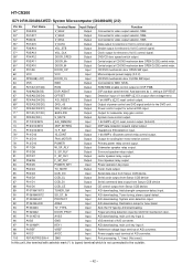
... Input A/D downloading. Port Name Terminal Name Input/Output Function 52* P42/A18 V_SEL2 Output Connected to video output selector, SW2. 53* P41/A17 V_SEL3 Output Connected to video output selector, SW4. 54* P40A16 V_SEL4 Output Connected to the outside. - 42 - HT-CN300 IC710 RH-iX0489AWZZ: System Microcomputer (IX0489AW) (2/2) Pin No. Destination setup for cooling fan motor rotation control. 78 P12/D10 POWER Output Primary power relay control ouput. 79 P11/D9 W_SP_RLY Output Subwoofer speaker...
... Input A/D downloading. Port Name Terminal Name Input/Output Function 52* P42/A18 V_SEL2 Output Connected to video output selector, SW2. 53* P41/A17 V_SEL3 Output Connected to video output selector, SW4. 54* P40A16 V_SEL4 Output Connected to the outside. - 42 - HT-CN300 IC710 RH-iX0489AWZZ: System Microcomputer (IX0489AW) (2/2) Pin No. Destination setup for cooling fan motor rotation control. 78 P12/D10 POWER Output Primary power relay control ouput. 79 P11/D9 W_SP_RLY Output Subwoofer speaker...
Service Manual
Page 43
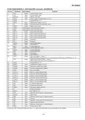
... pin). Input Power down & reset. Master clock input. Input Digital power supply, 4.5-5.5 V. Output Transmit channel (through data) output. Analog input overflow detect. (Note 1) When analog input of Lch or Rch overflows: "H" - Output Common voltage output, AVDD/2. Output DAC 2 R channel analog output. Input Slave mode. Input Receiver channel input 3 (internal bias pin). Input Serial control mode select. Chip address 0 Output Output Zero input detect 2. (Note 1) When input data in the group 2 is "0" continuously over 8192 times or RSTN bit is not connected to...
... pin). Input Power down & reset. Master clock input. Input Digital power supply, 4.5-5.5 V. Output Transmit channel (through data) output. Analog input overflow detect. (Note 1) When analog input of Lch or Rch overflows: "H" - Output Common voltage output, AVDD/2. Output DAC 2 R channel analog output. Input Slave mode. Input Receiver channel input 3 (internal bias pin). Input Serial control mode select. Chip address 0 Output Output Zero input detect 2. (Note 1) When input data in the group 2 is "0" continuously over 8192 times or RSTN bit is not connected to...

Service Manual
Page 45
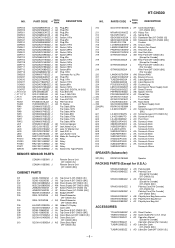
...; CY Square type (without lead wire) VR • • CZ Square type (without lead wire) VC J .. For U.S.A. Be sure to order. 3. HT-CN300 PARTS GUIDE HOME CINEMA COMMAND MODEL HT-CN300(S) HT-CN300 Home Cinema Command consisting of HT-CN300 (main unit), CP-CN300F (front speakers), CP-CN300C (center speaker) and CP-CN300R (surround speakers). REF. CAUTION:FOR CONTINUED PROTECTION AGAINST FIRE HAZARD, REPLACE ONLY WITH SAME TYPE F101,102...
...; CY Square type (without lead wire) VR • • CZ Square type (without lead wire) VC J .. For U.S.A. Be sure to order. 3. HT-CN300 PARTS GUIDE HOME CINEMA COMMAND MODEL HT-CN300(S) HT-CN300 Home Cinema Command consisting of HT-CN300 (main unit), CP-CN300F (front speakers), CP-CN300C (center speaker) and CP-CN300R (surround speakers). REF. CAUTION:FOR CONTINUED PROTECTION AGAINST FIRE HAZARD, REPLACE ONLY WITH SAME TYPE F101,102...
Service Manual
Page 51
... Display Flat Cable,25Pin Flat Cable,10Pin Flat Cable,14Pin Flat Cable,8Pin Flat Cable,17Pin Flat Cable,11Pin Flat Cable,19Pin AK Terminal,Speaker AF Jack,Video In/Out AF Jack,TV Monitor Out AF Jack,DVD In AH Jack,Audio In/Out AM Motor,Air Cooling Fan AK Relay AK Relay AK Relay AE Relay AC Switch,Key Type [Power] REMOTE SENSOR PARTS CCABA1012BGM1 J CCABA1012BGM2 J CABINET PARTS Remote Sensor Unit [HT-CN300 (S)] Remote...
... Display Flat Cable,25Pin Flat Cable,10Pin Flat Cable,14Pin Flat Cable,8Pin Flat Cable,17Pin Flat Cable,11Pin Flat Cable,19Pin AK Terminal,Speaker AF Jack,Video In/Out AF Jack,TV Monitor Out AF Jack,DVD In AH Jack,Audio In/Out AM Motor,Air Cooling Fan AK Relay AK Relay AK Relay AE Relay AC Switch,Key Type [Power] REMOTE SENSOR PARTS CCABA1012BGM1 J CCABA1012BGM2 J CABINET PARTS Remote Sensor Unit [HT-CN300 (S)] Remote...
Service Manual
Page 54
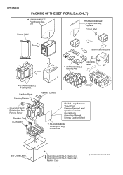
... Bag, Remote Sensor Speaker Cord AC Adaptor Remote Control FM/AM Loop Antenna Video Cord Remote Sensor Label Speaker Cushion Quick Guide Operation Manual Energy Caution Sheet SSAKA0002BGZZ Polyethylene Bag, Accessories Bar Code Label SPAKC0054BGZZ [HT-CN300 (S)] SPAKC0055BGZZ [HT-CN300 (BK)] Packing Case - 9 - : Not Replacement Item Label Front Bottom SPAKA0006BGZZ Packing Add. ONLY) SSAKH0008BGZZ Polyethylene Bag, Unit Energy Label SSAKH0006BGZZ Polyethylene Bag, Speaker Color Label Bottom Specifications Label SPAKA0007BGZZ...
... Bag, Remote Sensor Speaker Cord AC Adaptor Remote Control FM/AM Loop Antenna Video Cord Remote Sensor Label Speaker Cushion Quick Guide Operation Manual Energy Caution Sheet SSAKA0002BGZZ Polyethylene Bag, Accessories Bar Code Label SPAKC0054BGZZ [HT-CN300 (S)] SPAKC0055BGZZ [HT-CN300 (BK)] Packing Case - 9 - : Not Replacement Item Label Front Bottom SPAKA0006BGZZ Packing Add. ONLY) SSAKH0008BGZZ Polyethylene Bag, Unit Energy Label SSAKH0006BGZZ Polyethylene Bag, Speaker Color Label Bottom Specifications Label SPAKA0007BGZZ...


