
Service Manual
Page 1
... 3-1 [2] Removing and reinstalling the main part.s....... 3-5 CHAPTER 8. ADJUSTMENTS [1] Mechanism section 2-1 [2] Tuner section 2-1 [3] TEST MODE 2-2 [4] CD SECTION 2-4 [5] CD section 2-4 [6] Standard Specification of CD circuit 5-2 [4] Voltage 5-3 CHAPTER 6. CD-G10000/CP-G10000S SERVICE MANUAL No. In the interests of the set . SHARP CORPORATION This document has been published to change without notice. CIRCUIT SCHEMATICS AND PARTS LAYOUT [1] Schematic diagram 6-1 [2] Wiring side of the set . FLOWCHART [1] Troubleshooting 7-1 CHAPTER 3. The contents are important...
... 3-1 [2] Removing and reinstalling the main part.s....... 3-5 CHAPTER 8. ADJUSTMENTS [1] Mechanism section 2-1 [2] Tuner section 2-1 [3] TEST MODE 2-2 [4] CD SECTION 2-4 [5] CD section 2-4 [6] Standard Specification of CD circuit 5-2 [4] Voltage 5-3 CHAPTER 6. CD-G10000/CP-G10000S SERVICE MANUAL No. In the interests of the set . SHARP CORPORATION This document has been published to change without notice. CIRCUIT SCHEMATICS AND PARTS LAYOUT [1] Schematic diagram 6-1 [2] Wiring side of the set . FLOWCHART [1] Troubleshooting 7-1 CHAPTER 3. The contents are important...
Service Manual
Page 2
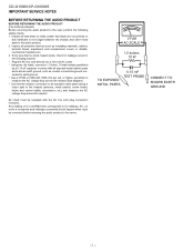
... EXPOSED METAL PARTS 0.15 mF TEST PROBE CONNECT TO KNOWN EARTH GROUND - Any reading of 0.3 volt RMS (this corresponds to the owner. Inspect all exposed metal parts having a return path to the chassis (antenna, metal cabinet, screw heads, knobs and control shafts, escutcheon, etc.) and measure the AC voltage drop across the resistor. CD-G10000/CP-G10000S IMPORTANT SERVICE NOTES BEFORE...
... EXPOSED METAL PARTS 0.15 mF TEST PROBE CONNECT TO KNOWN EARTH GROUND - Any reading of 0.3 volt RMS (this corresponds to the owner. Inspect all exposed metal parts having a return path to the chassis (antenna, metal cabinet, screw heads, knobs and control shafts, escutcheon, etc.) and measure the AC voltage drop across the resistor. CD-G10000/CP-G10000S IMPORTANT SERVICE NOTES BEFORE...
Service Manual
Page 3
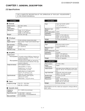
... watts minimum RMS per channel into 16 ohms from 5 kHz to 20 kHz, 10% total harmonic distortion Output terminals Front speakers: 8 ohms Rear speakers: 16 ohms Headphones: 16 - 50 ohms (recommended: 32 ohms) Subwoofer pre-out (audio signal): 200 mV/10 k ohms at 70 Hz Video out: 1 Vp-p (75 ohms) Input terminals Game/ Auxiliary (audio signal): 500 mV/ 47 k ohms Game/Video: 1 Vp-p (75 ohms) Tuner Frequency range FM: 87.5 - 108.0 MHz AM: 530 - 1,720 kHz Cassette deck Frequency...
... watts minimum RMS per channel into 16 ohms from 5 kHz to 20 kHz, 10% total harmonic distortion Output terminals Front speakers: 8 ohms Rear speakers: 16 ohms Headphones: 16 - 50 ohms (recommended: 32 ohms) Subwoofer pre-out (audio signal): 200 mV/10 k ohms at 70 Hz Video out: 1 Vp-p (75 ohms) Input terminals Game/ Auxiliary (audio signal): 500 mV/ 47 k ohms Game/Video: 1 Vp-p (75 ohms) Tuner Frequency range FM: 87.5 - 108.0 MHz AM: 530 - 1,720 kHz Cassette deck Frequency...

Service Manual
Page 4
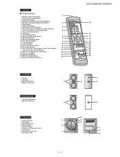
... Disc Pause Indicator 18. Subwoofer Pre-output Jack 3. FM Antenna Ground Terminal 4 6. Disc Tray Open/Close Button 7 16. Enter Button 8 18. MP3 Disc Navigation Mode Select Button 10 22. MP3 Folder Indicator 3. Tape 2 Record Indicator 9. Tuning Up Button 2 7. CD Button 29. Timer Play Indicator 7. Timer Recording Indicator 8. AC Power Cord 4. MP3 Title Indicators 4. FM Stereo Mode Indicator 11. Disc Repeat Play Indicator 17. FM 75 Ohms Antenna Terminal 5. AM Loop Antenna Jack 5 7. CD-G10000/CP-G10000S [2] Names of parts CD-G10000 Front panel...
... Disc Pause Indicator 18. Subwoofer Pre-output Jack 3. FM Antenna Ground Terminal 4 6. Disc Tray Open/Close Button 7 16. Enter Button 8 18. MP3 Disc Navigation Mode Select Button 10 22. MP3 Folder Indicator 3. Tape 2 Record Indicator 9. Tuning Up Button 2 7. CD Button 29. Timer Play Indicator 7. Timer Recording Indicator 8. AC Power Cord 4. MP3 Title Indicators 4. FM Stereo Mode Indicator 11. Disc Repeat Play Indicator 17. FM 75 Ohms Antenna Terminal 5. AM Loop Antenna Jack 5 7. CD-G10000/CP-G10000S [2] Names of parts CD-G10000 Front panel...
Service Manual
Page 5
... Input/Disc Direct Search Buttons 5. Equalizer Mode Select Button 5 14. Cursor Buttons 8 19. Disc Track Up or Fast Forward, Tape 2 Fast Forward, Tuner Preset Up, Time Up Button 10 11 22. Game/Video Button 13 25. Tweeter 3. Speaker Terminals CP-SW10000S 1. Power Switch 5. Cooling Fan 8. CD Button 12. Disc Random Button 7 17. Character Button 18. Disc Pause Button 21. Woofers 2. Full-range Speakers 2. Crossover Frequency Control 7. Memory/Set Button 8. Extra Bass Button 6 15. Disc Play or Repeat, Tape Play Button 12 23. MP3 Disc Display Button...
... Input/Disc Direct Search Buttons 5. Equalizer Mode Select Button 5 14. Cursor Buttons 8 19. Disc Track Up or Fast Forward, Tape 2 Fast Forward, Tuner Preset Up, Time Up Button 10 11 22. Game/Video Button 13 25. Tweeter 3. Speaker Terminals CP-SW10000S 1. Power Switch 5. Cooling Fan 8. CD Button 12. Disc Random Button 7 17. Character Button 18. Disc Pause Button 21. Woofers 2. Full-range Speakers 2. Crossover Frequency Control 7. Memory/Set Button 8. Extra Bass Button 6 15. Disc Play or Repeat, Tape Play Button 12 23. MP3 Disc Display Button...
Service Manual
Page 6
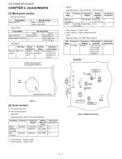
...; Tape Speed Normal speed Test Tape MTT-111 Adjusting Point Variable Resistor in motor Figure 1 [2] Tuner section fL: Low-range frequency fH: High-range frequency • AM IF/RF Signal generator: 400 Hz, 30%, AM modulated Test Stage AM IF AM Band Coverage AM Tracking Frequency 450 kHz - 990 kHz Frequency Display 1,720 kHz 530 kHz 990 kHz Setting/ Adjusting Parts T351 (fL): T306 1.1 ± 0.1 V (fL): T303 Instrument Connection *1 *2 *1 *1. Input: Antenna Output...
...; Tape Speed Normal speed Test Tape MTT-111 Adjusting Point Variable Resistor in motor Figure 1 [2] Tuner section fL: Low-range frequency fH: High-range frequency • AM IF/RF Signal generator: 400 Hz, 30%, AM modulated Test Stage AM IF AM Band Coverage AM Tracking Frequency 450 kHz - 990 kHz Frequency Display 1,720 kHz 530 kHz 990 kHz Setting/ Adjusting Parts T351 (fL): T306 1.1 ± 0.1 V (fL): T303 Instrument Connection *1 *2 *1 *1. Input: Antenna Output...
Service Manual
Page 7
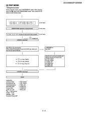
... using manual. Adjustment result automatically will display as below for each 2 sec: a) "FOF_XXXX" b) "TOF_XXXX" c) "TBAL_XX" d) "TGAN_XX" f) "FGAN_XX" g) "RFLS_XX" -------- FLAT X-BASS - then, press the CD button to page 2-3 Do TOC IL. IL isn't done key input. CD-G10000/CP-G10000S CD T EST IL isn't done OPEN/CLOSE operation is input into PLAY key, track number can be appoint directly. STOP explanation: a) Focus off set b)Tracking off set c)Tracking balance...
... using manual. Adjustment result automatically will display as below for each 2 sec: a) "FOF_XXXX" b) "TOF_XXXX" c) "TBAL_XX" d) "TGAN_XX" f) "FGAN_XX" g) "RFLS_XX" -------- FLAT X-BASS - then, press the CD button to page 2-3 Do TOC IL. IL isn't done key input. CD-G10000/CP-G10000S CD T EST IL isn't done OPEN/CLOSE operation is input into PLAY key, track number can be appoint directly. STOP explanation: a) Focus off set b)Tracking off set c)Tracking balance...

Service Manual
Page 8
Tracking ON play at that specific point. Laser ON. Adjustment result automatically will display as below for each 2 sec: a) "FOF_XXXX" b) "TOF_XXXX" c) "TBAL_XX" d) "TGAN_XX" f) "FGAN_XX" g) "RFLS_XX" key input. key input. Tracking OFF play from that specific point. CD-G10000/CP-G10000S A key input. key input. key input. STOP Sliding the PICKUP with>, > button must only be 2 - 3
Tracking ON play at that specific point. Laser ON. Adjustment result automatically will display as below for each 2 sec: a) "FOF_XXXX" b) "TOF_XXXX" c) "TBAL_XX" d) "TGAN_XX" f) "FGAN_XX" g) "RFLS_XX" key input. key input. Tracking OFF play from that specific point. CD-G10000/CP-G10000S A key input. key input. key input. STOP Sliding the PICKUP with>, > button must only be 2 - 3
Service Manual
Page 9
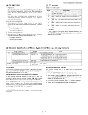
... Specification of each disc can be 0 dB.) * Focus gain adjustment * Tracking gain adjustment [5] CD section CD-G10000/CP-G10000S CD Error code description Error 01 10* 11* 20* 21* 31 Explanation When Pickup set tapering/parts replacement. 1. Press OPEN/CLOSE button until "WAIT"→ "FINISHED" appears. 4. TRAY error. When it change to +B PROTECTION. ** is changed, these adjustments are performed automatically. When it detect TRAY operation error during initialize process. CD DSP Communication Error. Display...
... Specification of each disc can be 0 dB.) * Focus gain adjustment * Tracking gain adjustment [5] CD section CD-G10000/CP-G10000S CD Error code description Error 01 10* 11* 20* 21* 31 Explanation When Pickup set tapering/parts replacement. 1. Press OPEN/CLOSE button until "WAIT"→ "FINISHED" appears. 4. TRAY error. When it change to +B PROTECTION. ** is changed, these adjustments are performed automatically. When it detect TRAY operation error during initialize process. CD DSP Communication Error. Display...

Service Manual
Page 42
... servicing the unit, be removed when disassembling the unit. Flat Cable B3) x1 4. Flat Wire E2) x1 3. Flat Cable F2) x1 7 Display PWB 1. Flat Cable J2) x2 3. Changer Chassis .... (K2) x1 11 CD Mechanism 1. Take off nylon bands or wire holders where they were before starting to remove the power supply plug from electrostatic damage. (A1)x3 M3x10mm Rear Panel B Top...
... servicing the unit, be removed when disassembling the unit. Flat Cable B3) x1 4. Flat Wire E2) x1 3. Flat Cable F2) x1 7 Display PWB 1. Flat Cable J2) x2 3. Changer Chassis .... (K2) x1 11 CD Mechanism 1. Take off nylon bands or wire holders where they were before starting to remove the power supply plug from electrostatic damage. (A1)x3 M3x10mm Rear Panel B Top...

Service Manual
Page 56
... Wiring Side of P.W.Board for this symbol P means pico-farad and the unit of the capacitor without any symbol is being played back. 5. In the tuner section, indicates AM indicates FM stereo 2. CD-G10000/CP-G10000S ACSMECeDuaHrdvr-kGiAioce1etP0M0T0aE0n/uRCaPl5-G.1C00IR00CSUIT DESCRIPTION [1] Notes on schematic diagram • Resistor: To differentiate the units of resistors, such symbol as K and M are used : this model...
... Wiring Side of P.W.Board for this symbol P means pico-farad and the unit of the capacitor without any symbol is being played back. 5. In the tuner section, indicates AM indicates FM stereo 2. CD-G10000/CP-G10000S ACSMECeDuaHrdvr-kGiAioce1etP0M0T0aE0n/uRCaPl5-G.1C00IR00CSUIT DESCRIPTION [1] Notes on schematic diagram • Resistor: To differentiate the units of resistors, such symbol as K and M are used : this model...

Service Manual
Page 67
.../ SET RD11 RD12 RD13 RD14 680 820 1K 1.5K SW712 SW713 SW714 SW715 SW729 SW730 SW731 SW732 SW733 SW734 SW735 OPEN/ CLOSE DIRECT PLAY DISC 2 DISC 4 DISC 5 DISC 3 RD15 RD16 RD17 RD18 RD19 RD20 DISC 1 RD21 2.2K 2.7K 3.9K 5.6K 10K 15K 33K SW716 SW717 SW718 SW719 SW720 SW721 SW722 SW723 TUNER (BAND) RD01 680 CD RD02 820 TAPE GAME/ X-BASS/ VIDEO DEMO...
.../ SET RD11 RD12 RD13 RD14 680 820 1K 1.5K SW712 SW713 SW714 SW715 SW729 SW730 SW731 SW732 SW733 SW734 SW735 OPEN/ CLOSE DIRECT PLAY DISC 2 DISC 4 DISC 5 DISC 3 RD15 RD16 RD17 RD18 RD19 RD20 DISC 1 RD21 2.2K 2.7K 3.9K 5.6K 10K 15K 33K SW716 SW717 SW718 SW719 SW720 SW721 SW722 SW723 TUNER (BAND) RD01 680 CD RD02 820 TAPE GAME/ X-BASS/ VIDEO DEMO...

Service Manual
Page 83
...Turn the power off any adjustment make certain that the lens is displayed. 1) Check the power to IC1 (LC78648E), the presence of the clock signal (16.9344 MHz) and the status of the RESET terminal (pin 67 on the CD cleaner disc which has the mark next to the PICKUP-IN Switch (NSW1) position? You will automatically stop button...optical pickup Lens cleaner disc Parts code UDSKA0004AFZZ HOW TO USE 1. Pressing the CD operation key is dirty. When the CD does not function The CD section may be effective for about 20 seconds and the CD player will hear music for 30-50 operations...
...Turn the power off any adjustment make certain that the lens is displayed. 1) Check the power to IC1 (LC78648E), the presence of the clock signal (16.9344 MHz) and the status of the RESET terminal (pin 67 on the CD cleaner disc which has the mark next to the PICKUP-IN Switch (NSW1) position? You will automatically stop button...optical pickup Lens cleaner disc Parts code UDSKA0004AFZZ HOW TO USE 1. Pressing the CD operation key is dirty. When the CD does not function The CD section may be effective for about 20 seconds and the CD player will hear music for 30-50 operations...

Service Manual
Page 84
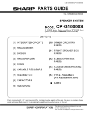
...Yes 2. When a disc is displayed. Yes 4. Is the turntable rotating? No If the level is generated, DRF will go H. CD-G10000/CP-G10000S (1) Focus-HF system check. Press the Tray1 CD Eject Button without inserting a disc, and try starting the playback operation. Stopped CH1=500 mV...Zoom : 2 K =Trigger= Mode : AUTO Type : EDGE CH1 Delay : 0.0 ns Hold off : 0.2 µs Figure 2 7 - 2 Figure 3 Vp-p=1.0 V~1.3 V 0.5 mV/div,0.5 µsec/div No Sled motor (NM2). Does the focus (lens) move to "H"? No Check the laser diode driver Q1 peripheral circuit. No Spindle ...
...Yes 2. When a disc is displayed. Yes 4. Is the turntable rotating? No If the level is generated, DRF will go H. CD-G10000/CP-G10000S (1) Focus-HF system check. Press the Tray1 CD Eject Button without inserting a disc, and try starting the playback operation. Stopped CH1=500 mV...Zoom : 2 K =Trigger= Mode : AUTO Type : EDGE CH1 Delay : 0.0 ns Hold off : 0.2 µs Figure 2 7 - 2 Figure 3 Vp-p=1.0 V~1.3 V 0.5 mV/div,0.5 µsec/div No Sled motor (NM2). Does the focus (lens) move to "H"? No Check the laser diode driver Q1 peripheral circuit. No Spindle ...

Service Manual
Page 87
... INternal signal monitor pin 1. LR channel GND pin. Setting in Reset ZHI AVDD1/2 - - - - - slice level con- A signal input pin. D signal input pin. Laser power control signal input pin. Analog power supply pin 2. Synchronization signal detection output pin. that are unused must be connected to 0 V. pose I /O pin 2. ACSMECeDuaHrdvr-kGiAioce1etP0M0T0aE0n/uRCaPl 8-G. 1O00T0H0SERS CD-G10000/CP-G10000S [1] Function table of these pose I/O pin 1. LVDD/2 - C1, C2 error correction monitor pin 7.35 kHz Synchronization signal output pin. Digital...
... INternal signal monitor pin 1. LR channel GND pin. Setting in Reset ZHI AVDD1/2 - - - - - slice level con- A signal input pin. D signal input pin. Laser power control signal input pin. Analog power supply pin 2. Synchronization signal detection output pin. that are unused must be connected to 0 V. pose I /O pin 2. ACSMECeDuaHrdvr-kGiAioce1etP0M0T0aE0n/uRCaPl 8-G. 1O00T0H0SERS CD-G10000/CP-G10000S [1] Function table of these pose I/O pin 1. LVDD/2 - C1, C2 error correction monitor pin 7.35 kHz Synchronization signal output pin. Digital...

Service Manual
Page 88
D/A converter R channel output supply pin. L Input Input L L L Input Input - - - - - Digital power supply pin. MONI3~5, DRF, WRQB pin output mode switching input pin. DAC external clock input pin. Bit clock output pin. Error flag monitor pin, or sub Controlled by commands from the micropro- sub code read clock input pin. open drain output DF. Phase comparison output pin 2 to all power supply pins, i, e., AVDD1, AVDD2, XVDD, DVDD, LVDD and RVDD) 8 - 2 Built-in VCO power supply pin. The...
D/A converter R channel output supply pin. L Input Input L L L Input Input - - - - - Digital power supply pin. MONI3~5, DRF, WRQB pin output mode switching input pin. DAC external clock input pin. Bit clock output pin. Error flag monitor pin, or sub Controlled by commands from the micropro- sub code read clock input pin. open drain output DF. Phase comparison output pin 2 to all power supply pins, i, e., AVDD1, AVDD2, XVDD, DVDD, LVDD and RVDD) 8 - 2 Built-in VCO power supply pin. The...

Service Manual
Page 93
... NO USE TRAY SW2 TRAY SW1 DISC SW CLAMP SW DIST S30-S20 S19/DEST0 S18/DEST1 S17/DEST2 S16/DEST3 Input/Output Input Output Output Output Output Output Input Output Output Input Output Input - - Input Input Input Input Input Input Input Input Input Input Input Input - Main clock output 4.19 MHz. Connect to the outside. 8 - 7 Power failure detect. 5-Changer Photo SW. Speaker abnormal detect. Ground voltage. New sound mode SW1. FL Segment driver. FL segment driver/Destination input. CD Chip enable. Tape Fool Proof A & B SW. Tape motor control. New sound mode...
... NO USE TRAY SW2 TRAY SW1 DISC SW CLAMP SW DIST S30-S20 S19/DEST0 S18/DEST1 S17/DEST2 S16/DEST3 Input/Output Input Output Output Output Output Output Input Output Output Input Output Input - - Input Input Input Input Input Input Input Input Input Input Input Input - Main clock output 4.19 MHz. Connect to the outside. 8 - 7 Power failure detect. 5-Changer Photo SW. Speaker abnormal detect. Ground voltage. New sound mode SW1. FL Segment driver. FL segment driver/Destination input. CD Chip enable. Tape Fool Proof A & B SW. Tape motor control. New sound mode...

Service Manual
Page 109
... SW734 92LSWICH1401AT AC SW735 92LSWICH1401AT AC WTM705 QCNCW019FAWZZ AB WTM901 QCNCW019EAWZZ AB Fuse,2A/125V Fuse,6A/125V Flat Cable,16Pin Flat Cable,11Pin Flat Cable,16Pin Flat Cable,7Pin Flat Cable,16Pin Ferrit Bead FL Display Flat Wire,6Pin Flat Wire,5Pin Jack,Game Input Jack,Video Out Jack,Headphones Jack,Subwoofer Pre-Out Switch,Jog Type [Volume] Lug Terminal Lug Terminal Lug Terminal Lug Terminal Motor with Gear...
... SW734 92LSWICH1401AT AC SW735 92LSWICH1401AT AC WTM705 QCNCW019FAWZZ AB WTM901 QCNCW019EAWZZ AB Fuse,2A/125V Fuse,6A/125V Flat Cable,16Pin Flat Cable,11Pin Flat Cable,16Pin Flat Cable,7Pin Flat Cable,16Pin Ferrit Bead FL Display Flat Wire,6Pin Flat Wire,5Pin Jack,Game Input Jack,Video Out Jack,Headphones Jack,Subwoofer Pre-Out Switch,Jog Type [Volume] Lug Terminal Lug Terminal Lug Terminal Lug Terminal Motor with Gear...
Service Manual
Page 127
... maintaining the safety and performance of the set . Be sure to replace these parts with " " are subject to be used for maintaining the safety of CP-G10000S (front speaker system) and CP-SW10000S (active subwoofer). CD-G10000/CP-G10000S PARTS GUIDE No. SHARP CORPORATION This document has been published to change without notice. The contents are important for after sales service only. CONTENTS [1] INTEGRATED CIRCUITS [2] TRANSISTORS [3] DIODES [10...
... maintaining the safety and performance of the set . Be sure to replace these parts with " " are subject to be used for maintaining the safety of CP-G10000S (front speaker system) and CP-SW10000S (active subwoofer). CD-G10000/CP-G10000S PARTS GUIDE No. SHARP CORPORATION This document has been published to change without notice. The contents are important for after sales service only. CONTENTS [1] INTEGRATED CIRCUITS [2] TRANSISTORS [3] DIODES [10...

Service Manual
Page 134
... Cover,Front White Reflector Edge Light Panel Decoration Cover,Rear Duct Port Ass'y Front Panel Ass'y Speaker Box Ass'y Rear Cover Knob,Power Knob,Volume/Crossover Frequency Bracket,Heat Sink Support Bracket,Fan Bushing,AC Power Supply Cord Chassis,Amp. ASSEMBLY (Not Replacement Item) ! PWB-A 92LPWB6242AMPS - ! CD-G10000/CP-G10000S NO. Chassis Heat Sink Heat Sink,Sub Spacer AC Power Supply Cord with CNS801 Holder,Fuse Label,Specifications Spring,Ring Nylon Band,80mm...
... Cover,Front White Reflector Edge Light Panel Decoration Cover,Rear Duct Port Ass'y Front Panel Ass'y Speaker Box Ass'y Rear Cover Knob,Power Knob,Volume/Crossover Frequency Bracket,Heat Sink Support Bracket,Fan Bushing,AC Power Supply Cord Chassis,Amp. ASSEMBLY (Not Replacement Item) ! PWB-A 92LPWB6242AMPS - ! CD-G10000/CP-G10000S NO. Chassis Heat Sink Heat Sink,Sub Spacer AC Power Supply Cord with CNS801 Holder,Fuse Label,Specifications Spring,Ring Nylon Band,80mm...


