
Manual
Page 3
ENEnGgLliIsShH CONTENTS Page ADJUSTING THE HAND POSITION 5 TIME/CALENDAR SETTING 6 STOPWATCH ...7 TACHYMETER ...9 NOTES ON USING THE WATCH 11 BATTERY CHANGE ...13 SPECIFICATIONS ...15 6 For the care of your watch, see "TO PRESERVE THE QUALITY OF YOUR WATCH" in the attached Worldwide Guarantee and Instruction Booklet. 3
ENEnGgLliIsShH CONTENTS Page ADJUSTING THE HAND POSITION 5 TIME/CALENDAR SETTING 6 STOPWATCH ...7 TACHYMETER ...9 NOTES ON USING THE WATCH 11 BATTERY CHANGE ...13 SPECIFICATIONS ...15 6 For the care of your watch, see "TO PRESERVE THE QUALITY OF YOUR WATCH" in the attached Worldwide Guarantee and Instruction Booklet. 3
Manual
Page 13
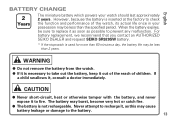
... soon as this may be less than 2 years. For battery replacement, we recommend that you contact an AUTHORIZED SEIKO DEALER and request SEIKO SR920SW battery. * If the stopwatch is necessary to take out the battery, keep it , as possible to replace it , consult a doctor immediately. q The battery is inserted at the factory to fire. When the...
... soon as this may be less than 2 years. For battery replacement, we recommend that you contact an AUTHORIZED SEIKO DEALER and request SEIKO SR920SW battery. * If the stopwatch is necessary to take out the battery, keep it , as possible to replace it , consult a doctor immediately. q The battery is inserted at the factory to fire. When the...
Manual
Page 14
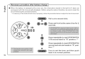
... back in IC does not correspond with a new one, the information stored in the built-in to normal position. 14 English Necessary procedure after battery change q When the battery is replaced with the time actually displayed. A « B A and B w A w Press and hold at the same time for 2 seconds. * STOPWATCH second hand turns half...
... back in IC does not correspond with a new one, the information stored in the built-in to normal position. 14 English Necessary procedure after battery change q When the battery is replaced with the time actually displayed. A « B A and B w A w Press and hold at the same time for 2 seconds. * STOPWATCH second hand turns half...
Manual
Page 15
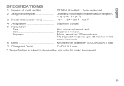
...° C (23° F ~ 122° F) 4 Driving system 5 Display system Time Date Stopwatch Step motor, 3 pieces Hour, minute and second hands Displayed in 1/10 second increments. 6 Battery Miniature silver oxide battery SEIKO SR920SW, 1 piece 7 IC (Integrated Circuit C-MOS-LSI, 1 piece * The specifications are subject to 60 minutes in numerals.
...° C (23° F ~ 122° F) 4 Driving system 5 Display system Time Date Stopwatch Step motor, 3 pieces Hour, minute and second hands Displayed in 1/10 second increments. 6 Battery Miniature silver oxide battery SEIKO SR920SW, 1 piece 7 IC (Integrated Circuit C-MOS-LSI, 1 piece * The specifications are subject to 60 minutes in numerals.
Parts Catalog
Page 1
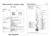
SEIKO SR920SW, Maxell SR920SW, Sony SR920SW, Eveready 371, Matsushita SR920SW Battery life is approximately 2 years. n it. 04 (). 0 z- Al Outside diameter Movement size Casing diameter Height Time indication Driving system Additional mechanism Loss/gain Regulation system Measuring gate by quartz tester Battery Jewels (X 1.0) 029.5 mm 26.0 mm between 3 o'clock and... Item -.._________ Cal. No am Movement V657A v., Ire. Pa. •••• reel • ' °:.. Voltage: 1.65V 0 jewel SEIKO CORPORATION 1 PARTS CATALOGUE Disassembling procedure Figs.
SEIKO SR920SW, Maxell SR920SW, Sony SR920SW, Eveready 371, Matsushita SR920SW Battery life is approximately 2 years. n it. 04 (). 0 z- Al Outside diameter Movement size Casing diameter Height Time indication Driving system Additional mechanism Loss/gain Regulation system Measuring gate by quartz tester Battery Jewels (X 1.0) 029.5 mm 26.0 mm between 3 o'clock and... Item -.._________ Cal. No am Movement V657A v., Ire. Pa. •••• reel • ' °:.. Voltage: 1.65V 0 jewel SEIKO CORPORATION 1 PARTS CATALOGUE Disassembling procedure Figs.
Parts Catalog
Page 2
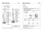
...wheel and pinion Those parts specified above are determined based on the extreme right. PARTS CATALOGUE Cal. PARTS CATALOGUE Cal. V657A •fe***4S -----1 Battery (See the front page.) Winding stem 25 0012 066 Switch spring screw S6 f'sk \ Switch spring 27 4003 029 Circuit block 28 4270 357... Battery connection I mt..4 0 N The numeral is printed on the designof cases, Check thecase number and refer to "CASING PARTS CATALOGUE" to the table below. ...
...wheel and pinion Those parts specified above are determined based on the extreme right. PARTS CATALOGUE Cal. PARTS CATALOGUE Cal. V657A •fe***4S -----1 Battery (See the front page.) Winding stem 25 0012 066 Switch spring screw S6 f'sk \ Switch spring 27 4003 029 Circuit block 28 4270 357... Battery connection I mt..4 0 N The numeral is printed on the designof cases, Check thecase number and refer to "CASING PARTS CATALOGUE" to the table below. ...
Parts Catalog
Page 3
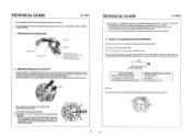
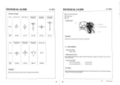
...minat Input terminal 1+) O C-MOS-LSI Crystal unit -- AVM -'I cio? •C) O 0 e • Before doing so, chock that the battery is re-installed following repairing procedures, be sure to short-circuit the AC terminal of Cal, V657A. • For the repairing, checking and measuring ...Chronograph minute, second and 1/10 second hands Since a plastic main plate is only for the particular points of the circuit block and the battery connection I . Cod block output terminal (tor motor driving center handsl II. The chronograph 1/10 second hand makes a full revolution clockwise...
...minat Input terminal 1+) O C-MOS-LSI Crystal unit -- AVM -'I cio? •C) O 0 e • Before doing so, chock that the battery is re-installed following repairing procedures, be sure to short-circuit the AC terminal of Cal, V657A. • For the repairing, checking and measuring ...Chronograph minute, second and 1/10 second hands Since a plastic main plate is only for the particular points of the circuit block and the battery connection I . Cod block output terminal (tor motor driving center handsl II. The chronograph 1/10 second hand makes a full revolution clockwise...
Parts Catalog
Page 5
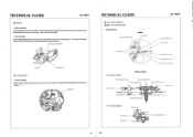
... plate securely. Step rotor (A) rJ Train wheel bridge (B) Center wheel and pinio Step rotor (B) Rotor stator Main plate -- Then, remove the battery. • How to remove Remove the winding stem with the crown at the normal position while pushing the setting lever (marked with "PUSH If... tweezers, catch the protrusion of the switch spring indicated in the illustration below, and detach the hooking portion from the main plate. V657A Z3 Battery • How to Minute wheel and pinion - TECHNICAL GUIDE Cal. Fourth wheel anti 1111110(1 Fifth wheel and pinion (A) Train wheel bridge (A)...
... plate securely. Step rotor (A) rJ Train wheel bridge (B) Center wheel and pinio Step rotor (B) Rotor stator Main plate -- Then, remove the battery. • How to remove Remove the winding stem with the crown at the normal position while pushing the setting lever (marked with "PUSH If... tweezers, catch the protrusion of the switch spring indicated in the illustration below, and detach the hooking portion from the main plate. V657A Z3 Battery • How to Minute wheel and pinion - TECHNICAL GUIDE Cal. Fourth wheel anti 1111110(1 Fifth wheel and pinion (A) Train wheel bridge (A)...
Parts Catalog
Page 6
... 0281 890 Remarks: Reassemble the step rotor (B) with conductive tweezers. 11 12 95.1 Printed in Japan Cal. V657A • Distinction of the circuit block and battery connection (+) with its pinion facing the main plate side. TECHNICAL GUIDE O Train wheel setting lever 54 Setting lever CI Yoke • Setting position r/ 0 Remarks: Check...
... 0281 890 Remarks: Reassemble the step rotor (B) with conductive tweezers. 11 12 95.1 Printed in Japan Cal. V657A • Distinction of the circuit block and battery connection (+) with its pinion facing the main plate side. TECHNICAL GUIDE O Train wheel setting lever 54 Setting lever CI Yoke • Setting position r/ 0 Remarks: Check...


