
Manual
Page 3
ENEnGgLliIsShH CONTENTS Page ADJUSTING THE HAND POSITION 5 TIME/CALENDAR SETTING 6 STOPWATCH ...7 TACHYMETER ...9 NOTES ON USING THE WATCH 11 BATTERY CHANGE ...13 SPECIFICATIONS ...15 6 For the care of your watch, see "TO PRESERVE THE QUALITY OF YOUR WATCH" in the attached Worldwide Guarantee and Instruction Booklet. 3
ENEnGgLliIsShH CONTENTS Page ADJUSTING THE HAND POSITION 5 TIME/CALENDAR SETTING 6 STOPWATCH ...7 TACHYMETER ...9 NOTES ON USING THE WATCH 11 BATTERY CHANGE ...13 SPECIFICATIONS ...15 6 For the care of your watch, see "TO PRESERVE THE QUALITY OF YOUR WATCH" in the attached Worldwide Guarantee and Instruction Booklet. 3
Manual
Page 13
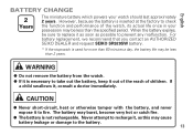
... you contact an AUTHORIZED SEIKO DEALER and request SEIKO SR920SW battery. * If the stopwatch is inserted at the factory to check the function and performance of children. WARNING q Do not remove the battery from the watch should last approximately 2 years. CAUTION q Never short-circuit, heat or otherwise tamper with the battery, and never expose it...
... you contact an AUTHORIZED SEIKO DEALER and request SEIKO SR920SW battery. * If the stopwatch is inserted at the factory to check the function and performance of children. WARNING q Do not remove the battery from the watch should last approximately 2 years. CAUTION q Never short-circuit, heat or otherwise tamper with the battery, and never expose it...
Manual
Page 14
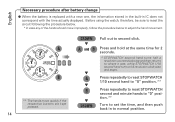
... at the same time for 2 seconds. * STOPWATCH second hand turns half a revolution counterclockwise and then returns to second click. English Necessary procedure after battery change q When the battery is replaced with a new one, the information stored in the built-in to adjust the hand movement. CROWN w Pull out to where it was...
... at the same time for 2 seconds. * STOPWATCH second hand turns half a revolution counterclockwise and then returns to second click. English Necessary procedure after battery change q When the battery is replaced with a new one, the information stored in the built-in to adjust the hand movement. CROWN w Pull out to where it was...
Manual
Page 15
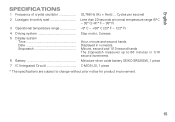
...° F ~ 122° F) 4 Driving system 5 Display system Time Date Stopwatch Step motor, 3 pieces Hour, minute and second hands Displayed in 1/10 second increments. 6 Battery Miniature silver oxide battery SEIKO SR920SW, 1 piece 7 IC (Integrated Circuit C-MOS-LSI, 1 piece * The specifications are subject to change without prior notice for product improvement. 15 English SPECIFICATIONS 1 Frequency...
...° F ~ 122° F) 4 Driving system 5 Display system Time Date Stopwatch Step motor, 3 pieces Hour, minute and second hands Displayed in 1/10 second increments. 6 Battery Miniature silver oxide battery SEIKO SR920SW, 1 piece 7 IC (Integrated Circuit C-MOS-LSI, 1 piece * The specifications are subject to change without prior notice for product improvement. 15 English SPECIFICATIONS 1 Frequency...
Parts Catalog
Page 1
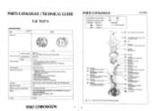
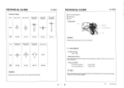
...Oil quantity Normal quantity Cal. o • 0 e . Reassembling procedure Figs. n it. 04 (). 0 z- SEIKO SR920SW, Maxell SR920SW, Sony SR920SW, Eveready 371, Matsushita SR920SW Battery life is approximately 2 years. PARTS CATALOGUE / TECHNICAL GUIDE Cal. Lubricating: Types of the hands Monthly rate at normal ...Al Outside diameter Movement size Casing diameter Height Time indication Driving system Additional mechanism Loss/gain Regulation system Measuring gate by quartz tester Battery Jewels (X 1.0) 029.5 mm 26.0 mm between 3 o'clock and 9 o'clock sides 028.8 mm 3.7 mm • ...
...Oil quantity Normal quantity Cal. o • 0 e . Reassembling procedure Figs. n it. 04 (). 0 z- SEIKO SR920SW, Maxell SR920SW, Sony SR920SW, Eveready 371, Matsushita SR920SW Battery life is approximately 2 years. PARTS CATALOGUE / TECHNICAL GUIDE Cal. Lubricating: Types of the hands Monthly rate at normal ...Al Outside diameter Movement size Casing diameter Height Time indication Driving system Additional mechanism Loss/gain Regulation system Measuring gate by quartz tester Battery Jewels (X 1.0) 029.5 mm 26.0 mm between 3 o'clock and 9 o'clock sides 028.8 mm 3.7 mm • ...
Parts Catalog
Page 2
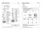
... designof cases, Check thecase number and refer to "CASING PARTS CATALOGUE" to the table below . PARTS CATALOGUE Cal. PARTS CATALOGUE Cal. V657A •fe***4S -----1 Battery (See the front page.) Winding stem 25 0012 066 Switch spring screw S6 f'sk \ Switch spring 27 4003 029 Circuit block 28 4270 357...
... designof cases, Check thecase number and refer to "CASING PARTS CATALOGUE" to the table below . PARTS CATALOGUE Cal. PARTS CATALOGUE Cal. V657A •fe***4S -----1 Battery (See the front page.) Winding stem 25 0012 066 Switch spring screw S6 f'sk \ Switch spring 27 4003 029 Circuit block 28 4270 357...
Parts Catalog
Page 3
...clock position "0" position 60 minute/second position (D Dial Pry up the dial at the sometime for the particular points of the circuit block and the battery connection I cio? •C) O 0 e • Pull out the crown to reset the circuit as specified below . 1. V657A 3. Press..., refer to be reset with conductive tweezers to the second click. 2. Follow the procedure below . III. Before doing so, chock that the battery is only for approximately 2 seconds. * The chronograph second hand makes half a revolution counterclockwise and then returns to the normal position. AVM -'I...
...clock position "0" position 60 minute/second position (D Dial Pry up the dial at the sometime for the particular points of the circuit block and the battery connection I cio? •C) O 0 e • Pull out the crown to reset the circuit as specified below . 1. V657A 3. Press..., refer to be reset with conductive tweezers to the second click. 2. Follow the procedure below . III. Before doing so, chock that the battery is only for approximately 2 seconds. * The chronograph second hand makes half a revolution counterclockwise and then returns to the normal position. AVM -'I...
Parts Catalog
Page 5
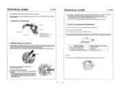
... switch spring indicated in the illustration below, and detach the hooking portion from the main plate. TECHNICAL GUIDE Cal. Then, remove the battery. • How to remove Remove the winding stem with the crown at the normal position while pushing the setting lever (marked with ... so that the hooking portion catches the main plate securely. Switch spring (battery clamp) 0 Protrusion Hooking portion 24) Winding stem • How to install Slip the battery sideways into the gap under the battery clamp of MHO 0 00 • 0 • 00 0 00 • 0 Setting lever TECHNICAL GUIDE ...
... switch spring indicated in the illustration below, and detach the hooking portion from the main plate. TECHNICAL GUIDE Cal. Then, remove the battery. • How to remove Remove the winding stem with the crown at the normal position while pushing the setting lever (marked with ... so that the hooking portion catches the main plate securely. Switch spring (battery clamp) 0 Protrusion Hooking portion 24) Winding stem • How to install Slip the battery sideways into the gap under the battery clamp of MHO 0 00 • 0 • 00 0 00 • 0 Setting lever TECHNICAL GUIDE ...
Parts Catalog
Page 6
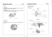
... circuit block alone Less than 3.0µA Less than 1.5µA 14' Before measuring the current consumption, short-circuit the AC terminal of the circuit block and battery connection (+) with its pinion facing the main plate side. TECHNICAL GUIDE O Train wheel setting lever 54 Setting lever CI Yoke • Setting position r/ 0 Remarks: Check...
... circuit block alone Less than 3.0µA Less than 1.5µA 14' Before measuring the current consumption, short-circuit the AC terminal of the circuit block and battery connection (+) with its pinion facing the main plate side. TECHNICAL GUIDE O Train wheel setting lever 54 Setting lever CI Yoke • Setting position r/ 0 Remarks: Check...


