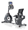
Assembly and Owner's Manual
Page 2
...360-859-5180, [email protected] | Printed in China | © 2013 Nautilus, Inc. 2 Assembly 3 Operations 27 Safety Warning Labels / Serial Number 4 Adjustments 27 Specifications 5 Power Up / Idle Mode 27 Before Assembly 5 Quick Start Program 28 Parts 6 User Profiles 28 Hardware 7 Pausing or Stopping 33 Tools 7 Results... / Cool Down Mode 34 Assembly 8 GOAL TRACK Statistics 34 Moving the Machine 18 Console Service Mode 36 Leveling the Machine 19 Maintenance 37 ...
Assembly and Owner's Manual
Page 3
...contains magnets. Failure to use only genuine Nautilus® replacement parts and hardware. Users may come into proximity of the magnets in the assembly, maintenance, and/or use of this equipment. Please consult the "Safety Warning Labels and Serial Number" section to users, keep the ...that you are necessary, use genuine replacement parts can lead to change the design or functionality of certain medical devices at all assembly steps in death or serious injury. Obey the following warnings: Read and understand all warnings on your medical provider in an appropriate...
Assembly and Owner's Manual
Page 5
...the State of a minimum 74.6" x 110.5" (189.5 cm x 280.5 cm). If you assemble your machine. Allow a workout area of California to our website at www.nautilus.com/prop65. Basic Assembly Tips Follow these basic points when you would like additional information, please refer to cause cancer, ...you are going to set up and operate your machine: • Read and understand the "Important Safety Instructions" before assembly. • Collect all the pieces necessary for each assembly step. • Using the recommended wrenches, turn the bolts and nuts to the right (clockwise) to help insert...
Assembly and Owner's Manual
Page 6
PARTS 17 16 15 14 13 12 2 1 5 6 7 3 4 9 11 8 10 Item Qty Description 1 1 Console 2 1 Water Bottle Holder 3 1 Seat Back 4 1 Seat Cover 5 1 Seat Frame Assembly 6 1 Seat Bottom 7 1 Seat Adjustment Handle 8 1 Rear Stabilizer 9 1 Frame Item Qty Description 10 1 AC Adapter 11 1 Left Pedal 12 1 Front Stabilizer 13 1 Right Pedal 14 1 Upper Shroud 15 1 Shroud Cap 16 1 Console Mast 17 1 MP3 Cord 6
Assembly and Owner's Manual
Page 8
ASSEMBLY 1. Attach Stabilizers to Frame Note: H ardware is pre-installed and not on the Hardware Card. * 6mm X2 * * * 6mm X2 * * * 8 9 12 8
Assembly and Owner's Manual
Page 9
2. Once all hardware has been inserted, be sure to the Seat Rail NOTICE: Do not crimp the Heart Rate Cable. Attach the Seat Frame Assembly to fully tighten it. 6mm X4 A D C 5 X2 B GE 4mm 9
Assembly and Owner's Manual
Page 10
Attach Seat Pads to Seat Frame Assembly 3 6 X8 E G B 4mm X4 H G I #2 10 3.
Assembly and Owner's Manual
Page 13
Connect the Cables and Attach the Console Mast to Frame Assembly NOTICE: Do not crimp Console Cables. 16 14 X4 A 6mm J D 15 13 6.
Assembly and Owner's Manual
Page 14
Note: H ardware is pre-installed and not on the cable connectors and make sure the connectors lock. Do not crimp cables. X4 14 Connect Cables and Attach Console to Frame Assembly NOTICE: Align the clips on the Hardware Card. * 1 X4 #2 8. Remove Hardware from Console NOTICE: Do not crimp the cable. * * 7.
Assembly and Owner's Manual
Page 15
The Left Pedal has an "L", the Right Pedal an "R". 13 11 15 Attach Pedals to attach Pedals on the bike. Be sure to Frame Assembly NOTICE: The Left Pedal is based from a seated position on the proper side of the Bike. Orientation is reverse-threaded. 9.
Assembly and Owner's Manual
Page 17
Final Inspection Inspect your machine to Frame Assembly 10 12. Do not use until the machine has been fully assembled and inspected for correct performance in the field provided at the front of this manual. Connect AC Adapter to ensure that all hardware is tight and components are properly assembled. Be sure to record the serial number in accordance with the Owner's Manual. 17 11.
Assembly and Owner's Manual
Page 39
A Console B Seat Back C Seat Cover D Water Bottle Holder E Handlebar, Side F Seat Bottom G Seat Adjustment Handle H Frame Assembly I Rear Stabilizer J Pedal, Left K Shroud, Left L Transport Wheel M Stabilizer, Front N Heart Rate Cable, Lower O Speed Sensor P Crank Arm Q Servo Motor R Brake Assembly S Flywheel T Drive Belt U Speed Sensor Magnet V Console Cable, Lower W Shroud, Right X Pedal, Right Y Shroud, Upper Z Shroud Cap AA Console Cable, Upper BB Heart Rate Cable, Upper CC Console Mast 39
Assembly and Owner's Manual
Page 41
...to the sensor or the connecting wire. Magnet should be in place on , but Console operates Unit rocks/does not sit level Seat Assembly shifts / squeaks when in use Pedals loose/unit difficult to pedal Check data cable integrity All wires in place on connector should be...of fan Check leveler adjustment Be sure cable is not cross threaded. Be sure cable is plugged into place. Check hardware that attaches Seat assembly, and fully tighten hardware. Crank should be aligned with removal. Check data cable connections/orientation Check magnet position (requires shroud removal) Check Speed...
Assembly and Owner's Manual
Page 42
...8226; Retain appropriate and acceptable Proof of Purchase. • Operate, maintain, and inspect the Product as specified in the Product Documentation (Assembly, Owner's Manuals, etc.). • Product must be used for the purpose intended, under normal conditions, and provided it receives proper ...long an implied warranty lasts, so the above , whichever is longer. Exclusions The preceding warranties are limited in the Product's Assembly and Owner's manual. Any implied warranties, including the WARRANTY OF MERCHANTABILITY and any warranty replacement parts will be prorated based ...
Assembly and Owner's Manual
Page 43
... to state. What Is Not Covered Damage due to abuse, tampering or modification of replacement parts involved in the Product's Assembly and Owner's manual. Damage due to improper storage or the effect of the United States consult your local distributor or dealer..., work places, clubs, fitness centers and any territories or countries outside of environmental conditions such as described in the initial product assembly and preventative maintenance services.) What You Must Do To arrange for authentic, original, legitimate machines manufactured by exceeding maximum user weights ...