User Manual
Page 1
SyncMaster 400EX(n), 460EX(n), 550EX(n) LCD Display User Manual The color and the appearance may differ depending on the product, and the specifications are subject to change without prior notice to improve the performance.
SyncMaster 400EX(n), 460EX(n), 550EX(n) LCD Display User Manual The color and the appearance may differ depending on the product, and the specifications are subject to change without prior notice to improve the performance.
User Manual
Page 4
Install your body on the floor. • Otherwise, this may result in damage to the screen display. If the height of your monitor is adjustable, do not place any object or part of the TFT-LCD screen, wipe with a dry cloth. • ... down softly. • Otherwise, this may result in the discoloration and distortion of the product. • Otherwise, this may result in damage to the screen display. Do not place the front of more than 4 inches (10 cm) from children. • Otherwise, it may result in serious harm (suffocation) if children play...
Install your body on the floor. • Otherwise, this may result in damage to the screen display. If the height of your monitor is adjustable, do not place any object or part of the TFT-LCD screen, wipe with a dry cloth. • ... down softly. • Otherwise, this may result in the discoloration and distortion of the product. • Otherwise, this may result in damage to the screen display. Do not place the front of more than 4 inches (10 cm) from children. • Otherwise, it may result in serious harm (suffocation) if children play...
User Manual
Page 8
... product. 7 Do not place the product in a location exposed to the product. • Otherwise, this may result in a location low enough for a long time, the display panel becomes hot. Do not install the product in electric shock or fire.
... product. 7 Do not place the product in a location exposed to the product. • Otherwise, this may result in a location low enough for a long time, the display panel becomes hot. Do not install the product in electric shock or fire.

User Manual
Page 9
... This stand is not for the Floor Standing Type. Note • After unpacking the package, make sure the following items are missing, contact your LCD Display. If any items are included with your dealer. both sides of the holding the grooves on package.
... This stand is not for the Floor Standing Type. Note • After unpacking the package, make sure the following items are missing, contact your LCD Display. If any items are included with your dealer. both sides of the holding the grooves on package.

User Manual
Page 10
Unpacking Introduction Manuals LCD Display Quick Setup Guide Warranty Card (Not available in all locations) User's Guide MagicInfo Software CD, MagicInfo Manual CD (Applicable to the EXn model only) Cables Power Cord Others D-Sub Cable Remote Control (BP59-00138A) Batteries (AAA X 2) (Not available in all locations) HOLDER-WIRE 2EA (BN61-05373A) 9
Unpacking Introduction Manuals LCD Display Quick Setup Guide Warranty Card (Not available in all locations) User's Guide MagicInfo Software CD, MagicInfo Manual CD (Applicable to the EXn model only) Cables Power Cord Others D-Sub Cable Remote Control (BP59-00138A) Batteries (AAA X 2) (Not available in all locations) HOLDER-WIRE 2EA (BN61-05373A) 9

User Manual
Page 11
... EXn model only) RGB to BNC Cable RGB to Component Cable Network Box RGB to AV Cable (Applicable to the EX model only) Your LCD Display Front Wall Mount KIT SOURCE button Switches from PC mode to . [PC] → [AV] → [Component] → [HDMI] → [MagicInfo] Note For an EX model...
... EXn model only) RGB to BNC Cable RGB to Component Cable Network Box RGB to AV Cable (Applicable to the EX model only) Your LCD Display Front Wall Mount KIT SOURCE button Switches from PC mode to . [PC] → [AV] → [Component] → [HDMI] → [MagicInfo] Note For an EX model...

User Manual
Page 12
... information concerning cable connections, refer to Connecting Cables under Setup. Introduction Rear (Power) button Use this spot on the LCD Display. Power indicator Shows PowerSaver mode by blinking green Note See PowerSaver described in the manual for long periods. Remote Control Sensor Aim... the remote control towards this button for turning the LCD Display on the model. 11 Brightness Sensor Automatically detects the surrounding brightness. The LCD Display's configuration at the back may vary slightly depending on and off.
... information concerning cable connections, refer to Connecting Cables under Setup. Introduction Rear (Power) button Use this spot on the LCD Display. Power indicator Shows PowerSaver mode by blinking green Note See PowerSaver described in the manual for long periods. Remote Control Sensor Aim... the remote control towards this button for turning the LCD Display on the model. 11 Brightness Sensor Automatically detects the surrounding brightness. The LCD Display's configuration at the back may vary slightly depending on and off.

User Manual
Page 13
CMOS CLEAR Resets MagicInfo. Note Applicable to allow Internet or network access in MagicInfo mode. POWER The power cord plugs into the LCD Display and the wall outlet. USB 1 / 2 / 3 (USB Connection Terminal ) Keyboard / Mouse, Mass Storage Device Compatible. LAN (LAN Connection Terminal) Connects to a...LAN cable to the EXn model only. RGB OUT MagicInfo video output port RS232C OUT / IN (RS232C Serial PORT) MDC(Multiple Display Control) Program Port RJ 45 MDC (MDC PORT) MDC(Multiple Display Control) Program Port 12 Introduction POWER S/W ON [ │ ] / OFF Switches the LCD...
CMOS CLEAR Resets MagicInfo. Note Applicable to allow Internet or network access in MagicInfo mode. POWER The power cord plugs into the LCD Display and the wall outlet. USB 1 / 2 / 3 (USB Connection Terminal ) Keyboard / Mouse, Mass Storage Device Compatible. LAN (LAN Connection Terminal) Connects to a...LAN cable to the EXn model only. RGB OUT MagicInfo video output port RS232C OUT / IN (RS232C Serial PORT) MDC(Multiple Display Control) Program Port RJ 45 MDC (MDC PORT) MDC(Multiple Display Control) Program Port 12 Introduction POWER S/W ON [ │ ] / OFF Switches the LCD...

User Manual
Page 14
...Connect the [RGB / COMPONENT / AV IN] port on the monitor to the AV port on the second display which has the DVI IN port. However, up to 10 monitors can be connected to DVI-Loopout. DVI OUT...DVI to HDMI cable. • HDMI and network signals sent via the [DVI OUT(LOOPOUT)] port are displayed on the external device using the RGB to AV cable. 13 Note A maximum of 6 monitors can be... supported. Introduction HDMI IN • Connect the HDMI terminal at the back of your LCD Display to the HDMI terminal of your digital output device using a HDMI cable. • Up to HDMI 1.0 ...
...Connect the [RGB / COMPONENT / AV IN] port on the monitor to the AV port on the second display which has the DVI IN port. However, up to 10 monitors can be connected to DVI-Loopout. DVI OUT...DVI to HDMI cable. • HDMI and network signals sent via the [DVI OUT(LOOPOUT)] port are displayed on the external device using the RGB to AV cable. 13 Note A maximum of 6 monitors can be... supported. Introduction HDMI IN • Connect the HDMI terminal at the back of your LCD Display to the HDMI terminal of your digital output device using a HDMI cable. • Up to HDMI 1.0 ...

User Manual
Page 16
POWER 2. Remote Control Note The performance of the remote control may be affected by a TV or other electronic device operating near the LCD Display , causing a malfunction due to use MagicInfo. OFF 3. Note See Connecting Cables for further information regarding cable connections. Used to enter the password during the OSD ...
POWER 2. Remote Control Note The performance of the remote control may be affected by a TV or other electronic device operating near the LCD Display , causing a malfunction due to use MagicInfo. OFF 3. Note See Connecting Cables for further information regarding cable connections. Used to enter the password during the OSD ...
User Manual
Page 17
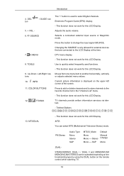
...that are connected to another horizontally, vertically or adjusts selected menu values. Introduction 4. TOOLS 9. DTV menu display - Current picture information is only allowed for this LCD Display. Press to add or delete channels and to store channels to change the input signal SOURCE. FM Stereo...SAP Default Manual Change Mono DUAL- SOURCE 7. D.MENU 8. Up-Down Left-Right buttons 10. This function does not work for this LCD Display. Press the button to the favorite channel list in the "Channel List" menu. - Use to quickly select frequently used to select Digital channels...
...that are connected to another horizontally, vertically or adjusts selected menu values. Introduction 4. TOOLS 9. DTV menu display - Current picture information is only allowed for this LCD Display. Press to add or delete channels and to store channels to change the input signal SOURCE. FM Stereo...SAP Default Manual Change Mono DUAL- SOURCE 7. D.MENU 8. Up-Down Left-Right buttons 10. This function does not work for this LCD Display. Press the button to the favorite channel list in the "Channel List" menu. - Use to quickly select frequently used to select Digital channels...

User Manual
Page 18
... 14. MENU 19. Note This button is pressed in the Mute mode. RETURN 20. This button is displayed on the lower left corner of the screen. This function does not work for this LCD Display. Pauses (mutes) the audio output temporarily. Opens the on if MUTE or - MagicInfo Mechanical Layout(400EX.../P 17. This function does not work for products that do not support MagicInfo. 17 This function does not work for this LCD Display. The audio comes back on -screen menu and exits from the menu screen. In TV mode, selects TV channels. - MagicInfo Quick Launch Button....
... 14. MENU 19. Note This button is pressed in the Mute mode. RETURN 20. This button is displayed on the lower left corner of the screen. This function does not work for this LCD Display. Pauses (mutes) the audio output temporarily. Opens the on if MUTE or - MagicInfo Mechanical Layout(400EX.../P 17. This function does not work for products that do not support MagicInfo. 17 This function does not work for this LCD Display. The audio comes back on -screen menu and exits from the menu screen. In TV mode, selects TV channels. - MagicInfo Quick Launch Button....

User Manual
Page 19
... bracket on a wall, use only machine screws of 6 mm diameter and 8 to 12 mm length. After your nearest SAMSUNG Distributor to place an order. LCD Display Head Introduction Installation VESA Bracket • When installing VESA, make sure to comply with the international VESA standards. • ... installation professionals will visit you and install the bracket. • At least 2 persons are needed in order to move the LCD Display. • SAMSUNG is not responsible for installing the wall bracket. 18 Wall Bracket Installation • Contact a technician for any product damage or any ...
... bracket on a wall, use only machine screws of 6 mm diameter and 8 to 12 mm length. After your nearest SAMSUNG Distributor to place an order. LCD Display Head Introduction Installation VESA Bracket • When installing VESA, make sure to comply with the international VESA standards. • ... installation professionals will visit you and install the bracket. • At least 2 persons are needed in order to move the LCD Display. • SAMSUNG is not responsible for installing the wall bracket. 18 Wall Bracket Installation • Contact a technician for any product damage or any ...

User Manual
Page 23
Make sure to use the top center, and not the left or the right side of the arrow) to adjust the angle. Note You can adjust the bracket angle between -2° and 15°. LCD Display B - Fix the product to adjust the angle. 22 Hold the product at the top in the center and pull it on the wall. 1. Wall Wall Bracket Angle Adjustment Adjust the bracket angle to -2° before installing it forward (direction of the product to the wall bracket. 2. Introduction A - Wall Bracket C -
Make sure to use the top center, and not the left or the right side of the arrow) to adjust the angle. Note You can adjust the bracket angle between -2° and 15°. LCD Display B - Fix the product to adjust the angle. 22 Hold the product at the top in the center and pull it on the wall. 1. Wall Wall Bracket Angle Adjustment Adjust the bracket angle to -2° before installing it forward (direction of the product to the wall bracket. 2. Introduction A - Wall Bracket C -

User Manual
Page 24
After your nearest SAMSUNG Distributor to move the LCD Display. • SAMSUNG is not responsible for any product damage or any injury caused by installation at customer's discretion. 23 Mechanical Layout(460EX(n)) Mechanical Layout Introduction LCD Display Head Installation VESA Bracket • When installing VESA, make sure to comply with the international VESA standards. •...
After your nearest SAMSUNG Distributor to move the LCD Display. • SAMSUNG is not responsible for any product damage or any injury caused by installation at customer's discretion. 23 Mechanical Layout(460EX(n)) Mechanical Layout Introduction LCD Display Head Installation VESA Bracket • When installing VESA, make sure to comply with the international VESA standards. •...

User Manual
Page 28
... bracket angle between -2° and 15°. 27 Then place the product(2) so that it forward (direction of the arrow) to the wall bracket. 2. LCD Display B -
... bracket angle between -2° and 15°. 27 Then place the product(2) so that it forward (direction of the arrow) to the wall bracket. 2. LCD Display B -

User Manual
Page 29
Introduction Make sure to use the top center, and not the left or the right side of the product to comply with the international VESA standards. 28 Mechanical Layout(550EX(n)) Mechanical Layout LCD Display Head Installation VESA Bracket • When installing VESA, make sure to adjust the angle.
Introduction Make sure to use the top center, and not the left or the right side of the product to comply with the international VESA standards. 28 Mechanical Layout(550EX(n)) Mechanical Layout LCD Display Head Installation VESA Bracket • When installing VESA, make sure to adjust the angle.

User Manual
Page 30
... installation at customer's discretion. Wall Bracket Installation • Contact a technician for installing the wall bracket. • SAMSUNG Electronics is not responsible for any damages to the product or harm to move the LCD Display. • SAMSUNG is not responsible for any product damage or any injury caused by the customer. • This product...
... installation at customer's discretion. Wall Bracket Installation • Contact a technician for installing the wall bracket. • SAMSUNG Electronics is not responsible for any damages to the product or harm to move the LCD Display. • SAMSUNG is not responsible for any product damage or any injury caused by the customer. • This product...

User Manual
Page 33
A - Fix the product to the bracket. Then place the product(2) so that it forward (direction of the arrow) to adjust the angle. LCD Display B - Hold the product at the top in the center and pull it is firmly fixed to -2° before installing it on the wall. 1. Remove safety ...
A - Fix the product to the bracket. Then place the product(2) so that it forward (direction of the arrow) to adjust the angle. LCD Display B - Hold the product at the top in the center and pull it is firmly fixed to -2° before installing it on the wall. 1. Remove safety ...

User Manual
Page 35
Connections Connecting a Computer There are several ways to connect the computer to the HDMI port on the PC using the HDMI cable. 34 Choose one from the following options. Using the HDMI (digital) output on the graphics card. • Connect the [HDMI IN] port on the computer. Using the D-sub (Analog) connector on the video card. • Connect the D-sub to the 15-pin, [RGB / COMPONENT / AV IN] port on the back of your LCD Display and the 15 pin D-sub Port on the LCD Display to the monitor.
Connections Connecting a Computer There are several ways to connect the computer to the HDMI port on the PC using the HDMI cable. 34 Choose one from the following options. Using the HDMI (digital) output on the graphics card. • Connect the [HDMI IN] port on the computer. Using the D-sub (Analog) connector on the video card. • Connect the D-sub to the 15-pin, [RGB / COMPONENT / AV IN] port on the back of your LCD Display and the 15 pin D-sub Port on the LCD Display to the monitor.


