
Quick Guide (ENGLISH)
Page 4
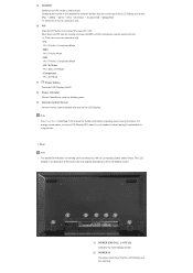
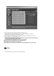
The LCD Display 's configuration at the time. [PC] → [BNC] → [DVI] → [AV] → [S-Video] → [Component] → [MagicNet] >> Click here to see an animation clip. 6) PIP Push the PIP button to see an animation clip. • PC AV / S-Video / Component Mode • BNC AV ... the PIP screen On / Off. More than one PIP cannot overlap on screen as BNC and the component use the same terminal. >> Click here to turn your LCD Display OFF when it is not needed or when leaving it unattended for long periods. Changing the source is only allowed for further information...
The LCD Display 's configuration at the time. [PC] → [BNC] → [DVI] → [AV] → [S-Video] → [Component] → [MagicNet] >> Click here to see an animation clip. 6) PIP Push the PIP button to see an animation clip. • PC AV / S-Video / Component Mode • BNC AV ... the PIP screen On / Off. More than one PIP cannot overlap on screen as BNC and the component use the same terminal. >> Click here to turn your LCD Display OFF when it is not needed or when leaving it unattended for long periods. Changing the source is only allowed for further information...

Quick Guide (ENGLISH)
Page 11
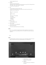
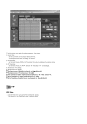
...Changing the source is only allowed for external devices that are connected to the LCD Display at the back may vary slightly depending on screen as BNC and the component use the same terminal. >> Click here to see an animation clip. 6) PIP Push the PIP button to see...item. 5) SOURCE Switches from PC mode to Connecting Cables under Setup. The LCD Display 's configuration at the time. [PC] → [BNC] → [DVI] → [AV] → [S-Video] → [Component] >> Click here to turn your LCD Display OFF when it is not needed or when leaving it unattended for further information ...
...Changing the source is only allowed for external devices that are connected to the LCD Display at the back may vary slightly depending on screen as BNC and the component use the same terminal. >> Click here to see an animation clip. 6) PIP Push the PIP button to see...item. 5) SOURCE Switches from PC mode to Connecting Cables under Setup. The LCD Display 's configuration at the time. [PC] → [BNC] → [DVI] → [AV] → [S-Video] → [Component] >> Click here to turn your LCD Display OFF when it is not needed or when leaving it unattended for further information ...
User Manual (ENGLISH)
Page 13
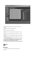
...mode. Note • See PowerSaver described in the manual for long periods. The LCD Display 's configuration at the time. [PC] → [BNC] → [DVI] → [AV] → [S-Video] → [Component] → [MagicNet] >> Click here to see an animation clip. 6) PIP Push the PIP button to see... Control Sensor Aim the remote control towards this spot on screen as BNC and the component use the same terminal. >> Click here to turn your LCD Display OFF when it unattended for further information regarding power saving functions. For energy conservation, turn the PIP screen On / Off...
...mode. Note • See PowerSaver described in the manual for long periods. The LCD Display 's configuration at the time. [PC] → [BNC] → [DVI] → [AV] → [S-Video] → [Component] → [MagicNet] >> Click here to see an animation clip. 6) PIP Push the PIP button to see... Control Sensor Aim the remote control towards this spot on screen as BNC and the component use the same terminal. >> Click here to turn your LCD Display OFF when it unattended for further information regarding power saving functions. For energy conservation, turn the PIP screen On / Off...
User Manual (ENGLISH)
Page 20
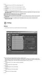
Note • See PowerSaver described in the manual for long periods. The LCD Display 's configuration at the time. [PC] → [BNC] → [DVI] → [AV] → [S-Video] → [Component] >> Click here to see an animation clip. • PC AV / S-Video / Component Mode • BNC AV / S-Video Mode •... it is only allowed for external devices that are connected to the LCD Display at the back may vary slightly depending on screen as BNC and the component use the same terminal. >> Click here to Connecting Cables under Setup. For energy conservation, turn the ...
Note • See PowerSaver described in the manual for long periods. The LCD Display 's configuration at the time. [PC] → [BNC] → [DVI] → [AV] → [S-Video] → [Component] >> Click here to see an animation clip. • PC AV / S-Video / Component Mode • BNC AV / S-Video Mode •... it is only allowed for external devices that are connected to the LCD Display at the back may vary slightly depending on screen as BNC and the component use the same terminal. >> Click here to Connecting Cables under Setup. For energy conservation, turn the ...
User Manual (ENGLISH)
Page 53
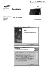
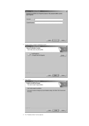
...Click the MagicNet installation file. 3. Select "I agree to the terms of the license agreement" to accept the terms of performance enhancement. You are logged in to the MagicNet Server program. Please enter the password to login. Insert the installation CD into the CD-ROM drive. 2. SyncMaster 400PXn/460PXn... Select Language Main Page Model Safety Instructions Introduction Connections Using the Software Installation MagicNet MDC MagicNet Adjusting the LCD Display Troubleshooting Specifications Information DAoppdeantdaikx The color...
...Click the MagicNet installation file. 3. Select "I agree to the terms of the license agreement" to accept the terms of performance enhancement. You are logged in to the MagicNet Server program. Please enter the password to login. Insert the installation CD into the CD-ROM drive. 2. SyncMaster 400PXn/460PXn... Select Language Main Page Model Safety Instructions Introduction Connections Using the Software Installation MagicNet MDC MagicNet Adjusting the LCD Display Troubleshooting Specifications Information DAoppdeantdaikx The color...
User Manual (ENGLISH)
Page 54
Click "Install." 8. Choose a folder to install the MagicNet program. 7. The "Installation Status" window appears. 6.
Click "Install." 8. Choose a folder to install the MagicNet program. 7. The "Installation Status" window appears. 6.

User Manual (ENGLISH)
Page 55
Click "Finish." 10. 9. When the installation is recommended restarting the system for the normal operation of the MagicNet Server program. ALL Right Reserved Double-click the icon to start the program. System Requirements Minimum Recommended CPU RAM Ethernet P1.8 P3.0Ghz 256M 512M 100M/1G OS Windows XP Windows 2000 (Service Pack 4) Application WMP 9 or later © 1995~2007 SAMSUNG. It is complete, the MagicNet executable icon appears on your desktop. 11.
Click "Finish." 10. 9. When the installation is recommended restarting the system for the normal operation of the MagicNet Server program. ALL Right Reserved Double-click the icon to start the program. System Requirements Minimum Recommended CPU RAM Ethernet P1.8 P3.0Ghz 256M 512M 100M/1G OS Windows XP Windows 2000 (Service Pack 4) Application WMP 9 or later © 1995~2007 SAMSUNG. It is complete, the MagicNet executable icon appears on your desktop. 11.

User Manual (ENGLISH)
Page 56
Introduction A Multiple Display Control (MDC) is used for the communication between the serial port on a PC and the serial port on a PC. RS-232C, a standard of the selected set to see the volume of serial communication, is an application allowing various displays to start the program. Therefore, a serial cable should be easily and simultaneously operated on a display. Select a set within the slider. Main Screen Click Start > Program > Samsung > MDC System to be connected between a PC and a display.
Introduction A Multiple Display Control (MDC) is used for the communication between the serial port on a PC and the serial port on a PC. RS-232C, a standard of the selected set to see the volume of serial communication, is an application allowing various displays to start the program. Therefore, a serial cable should be easily and simultaneously operated on a display. Select a set within the slider. Main Screen Click Start > Program > Samsung > MDC System to be connected between a PC and a display.

User Manual (ENGLISH)
Page 57
.... Use Control Tools to Enable when the MDC is On/Off, and this applies to all displays connected to enable or disable the remote control signal receiving function of all displays is COM1. 5. However, regardless of the status at the time the MDC is shut down,...all or Clear to view brief information on the remote control and set. 4. Select a display from Display Selection. 8. Main Icons Remocon Safety Lock Port Selection Select Button Info Grid Display Selection Control Tools 1. Click Select all displays. 6. Port Selection Use the main icons to switch into each screen. 2. Set the...
.... Use Control Tools to Enable when the MDC is On/Off, and this applies to all displays connected to enable or disable the remote control signal receiving function of all displays is COM1. 5. However, regardless of the status at the time the MDC is shut down,...all or Clear to view brief information on the remote control and set. 4. Select a display from Display Selection. 8. Main Icons Remocon Safety Lock Port Selection Select Button Info Grid Display Selection Control Tools 1. Click Select all displays. 6. Port Selection Use the main icons to switch into each screen. 2. Set the...

User Manual (ENGLISH)
Page 58
If the exact port name that is connected to COM1. 2. Power Control 1. If any port other than COM1 is not selected, communication will be selected in the program and used , COM1 through COM4 can be unavailable. 4. 1. Click Power Control of the main icons and the Power Control screen appears. The selected port is originally set to the LCD Display using a serial cable is used for the next program as well. The Multiple Display Control is stored in the Port Selection Menu. 3.
If the exact port name that is connected to COM1. 2. Power Control 1. If any port other than COM1 is not selected, communication will be selected in the program and used , COM1 through COM4 can be unavailable. 4. 1. Click Power Control of the main icons and the Power Control screen appears. The selected port is originally set to the LCD Display using a serial cable is used for the next program as well. The Multiple Display Control is stored in the Port Selection Menu. 3.
User Manual (ENGLISH)
Page 60
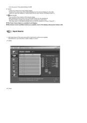
...main icons and the Input Source control screen appears. Click Input Source of the selected display On/Off. 2) Volume - It receives the volume value of the selected display. Controls the volume level of the selected display from the sets and displays it in the slider. (When you undo the selections... Volume Control and Mute features are available only for the displays whose power status is available for the selected set at a time, turn on /off the Mute function of the selected display. Click Select All or use Check Box to select a display to the default value 10) 3) (Mute On/Off)...
...main icons and the Input Source control screen appears. Click Input Source of the selected display On/Off. 2) Volume - It receives the volume value of the selected display. Controls the volume level of the selected display from the sets and displays it in the slider. (When you undo the selections... Volume Control and Mute features are available only for the displays whose power status is available for the selected set at a time, turn on /off the Mute function of the selected display. Click Select All or use Check Box to select a display to the default value 10) 3) (Mute On/Off)...
User Manual (ENGLISH)
Page 61
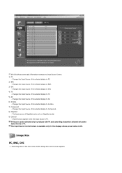
...Input Source Control feature is available only for the displays whose power status is TV. Image Size PC, BNC, DVI 1. Changes the Input Source of the main icons and the Image Size control screen appears. Click Image Size of the selected display to S-Video. 7) Component - Changes the ...Input Source of the selected display to AV. 6) S-Video - Changes the Input Source of the selected display to TV. 5) AV - Channel arrow appears when the ...
...Input Source Control feature is available only for the displays whose power status is TV. Image Size PC, BNC, DVI 1. Changes the Input Source of the main icons and the Image Size control screen appears. Click Image Size of the selected display to S-Video. 7) Component - Changes the ...Input Source of the selected display to AV. 6) S-Video - Changes the Input Source of the selected display to TV. 5) AV - Channel arrow appears when the ...
User Manual (ENGLISH)
Page 62
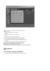
... information necessary to control Image Size for respective Input Source. Shows the power status of the display in use . 3) Input - Image Size TV, AV, S-Video, Component, DVI(HDCP) 1. When you click Image Size, the PC Source tab first appear. - The Image Size Control button controls Image... Size available for which power status is PC, BNC, DVI. 5) PC Source - Image Size Control is available only for the displays for PC, BNC, DVI. 6) Video Source...
... information necessary to control Image Size for respective Input Source. Shows the power status of the display in use . 3) Input - Image Size TV, AV, S-Video, Component, DVI(HDCP) 1. When you click Image Size, the PC Source tab first appear. - The Image Size Control button controls Image... Size available for which power status is PC, BNC, DVI. 5) PC Source - Image Size Control is available only for the displays for PC, BNC, DVI. 6) Video Source...
User Manual (ENGLISH)
Page 63
... power status is ON. The Input source of the selected display randomly. Time 1. Info Grid shows some basic information necessary to Image Size Control. 1) Click the Video Source tab to control. 2) Info Grid displays only the display having TV, AV, S-Video, Component or DVI(HDCP) as input source. 3)... Switch Image Size of TV works only on MagicNet model. Click Time of MagicNet works only on TV ...
... power status is ON. The Input source of the selected display randomly. Time 1. Info Grid shows some basic information necessary to Image Size Control. 1) Click the Video Source tab to control. 2) Info Grid displays only the display having TV, AV, S-Video, Component or DVI(HDCP) as input source. 3)... Switch Image Size of TV works only on MagicNet model. Click Time of MagicNet works only on TV ...
User Manual (ENGLISH)
Page 64
...MagicNet Model. Set the Hour, Minute, and AM/PM, Status for Off Time Setup of the main icons and the PIP control screen appears. Click PIP of the selected display. 4) Shows the On Time settings. 5) Shows the Off Time settings. At On Time Setup, MagicNet Source functions only for the selected...Time. 2) On Time Setup - The Input source of TV works only on MagicNet model. PIP PIP Size 1. Time Control is available only for the displays for TV Model. Info Grid shows some basic information necessary to control. Set the Hour, Minute, AM/PM of On Time Setup, Status, Source, ...
...MagicNet Model. Set the Hour, Minute, and AM/PM, Status for Off Time Setup of the main icons and the PIP control screen appears. Click PIP of the selected display. 4) Shows the On Time settings. 5) Shows the Off Time settings. At On Time Setup, MagicNet Source functions only for the selected...Time. 2) On Time Setup - The Input source of TV works only on MagicNet model. PIP PIP Size 1. Time Control is available only for the displays for TV Model. Info Grid shows some basic information necessary to control. Set the Hour, Minute, AM/PM of On Time Setup, Status, Source, ...
User Manual (ENGLISH)
Page 65
... 5) Double 1 - Turns off the PIP of the selected display and changes the size to Double 2. 7) Double 3 (Picture By Picture) - Click PIP of the selected display and changes the size to Large. 4) Small - Turns on the PBP of the selected display and changes the size to PIP Size Control. 1) PIP Size... - Turns on the PIP of the main icons and the PIP control screen appears. • PIP TV Mode PIP PIP Source 1. Turns on the LCD Display...
... 5) Double 1 - Turns off the PIP of the selected display and changes the size to Double 2. 7) Double 3 (Picture By Picture) - Click PIP of the selected display and changes the size to Large. 4) Small - Turns on the PBP of the selected display and changes the size to PIP Size Control. 1) PIP Size... - Turns on the PIP of the main icons and the PIP control screen appears. • PIP TV Mode PIP PIP Source 1. Turns on the LCD Display...
User Manual (ENGLISH)
Page 67
... 8) Component - Settings Picture 1. Adjusts Contrast of the selected display. 5) Color - 6) AV - Adjusts Sharpness of the selected display. 3) Brightness - Changing a value in this screen will automatically change the mode to Component. 9) Channel - Click Settings of the PIP Sources may not be selected only in ...the slide.When selected, each function is selected, the set value of the selected display to "CUSTOM." 1) Picture - Note: Some of the ...
... 8) Component - Settings Picture 1. Adjusts Contrast of the selected display. 5) Color - 6) AV - Adjusts Sharpness of the selected display. 3) Brightness - Changing a value in this screen will automatically change the mode to Component. 9) Channel - Click Settings of the PIP Sources may not be selected only in ...the slide.When selected, each function is selected, the set value of the selected display to "CUSTOM." 1) Picture - Note: Some of the ...
User Manual (ENGLISH)
Page 68
... works only on MagicNet model. The Input source of the selected display. - Adjusts Tint of MagicNet works only on TV model. Available only for the selected display. 4) Red - The Input source of the main icons and the Settings Control screen appears. Click Settings of MagicNet works only on the slide bar. Available only...
... works only on MagicNet model. The Input source of the selected display. - Adjusts Tint of MagicNet works only on TV model. Available only for the selected display. 4) Red - The Input source of the main icons and the Settings Control screen appears. Click Settings of MagicNet works only on the slide bar. Available only...

User Manual (ENGLISH)
Page 69
...This feature is available only for the displays whose power status is ON and if no selection is made , the factory default is displayed. Click Settings of the selected display. 4) Balance - When selected, each function is selected, the set and displays it on the slide bar. Adjusts... Bass of the selected display. 5) SRS TSXT - Select either Main or Sub when PIP is displayed. When "Select All" is...
...This feature is available only for the displays whose power status is ON and if no selection is made , the factory default is displayed. Click Settings of the selected display. 4) Balance - When selected, each function is selected, the set and displays it on the slide bar. Adjusts... Bass of the selected display. 5) SRS TSXT - Select either Main or Sub when PIP is displayed. When "Select All" is...

User Manual (ENGLISH)
Page 70
...necessary to the incoming PC signal. Available only for which the power status is ON. The Input source of the selected display. 5) Auto Adjustment - Click Settings of the selected display. 3) Fine - Adjusts Coarse of the main icons and the Settings Control screen appears. Adjusts Fine of TV works only... on the "Maintenance" icon in the Main Icon column to display the Maintenance screen. Maintenance Lamp Control 1. Self-Adjust to Settings Control. 1) Image Lock - Click on TV model. The Input source of the selected...
...necessary to the incoming PC signal. Available only for which the power status is ON. The Input source of the selected display. 5) Auto Adjustment - Click Settings of the selected display. 3) Fine - Adjusts Coarse of the main icons and the Settings Control screen appears. Adjusts Fine of TV works only... on the "Maintenance" icon in the Main Icon column to display the Maintenance screen. Maintenance Lamp Control 1. Self-Adjust to Settings Control. 1) Image Lock - Click on TV model. The Input source of the selected...


