Operation Manual
Page 3
... is off when plugging in any other part that can get caught and draw you into a blade or cutter against the direction or rotation of moving parts. Also wear protective hair covering to this tool. GUARD AGAINST ELECTRICAL SHOCK BY PREVENTING BODY CONTACT WITH GROUNDED SURFACES. When not in doubt, use...
... is off when plugging in any other part that can get caught and draw you into a blade or cutter against the direction or rotation of moving parts. Also wear protective hair covering to this tool. GUARD AGAINST ELECTRICAL SHOCK BY PREVENTING BODY CONTACT WITH GROUNDED SURFACES. When not in doubt, use...
Operation Manual
Page 5
...61550; NEVER stand or have damaged, missing, or failed parts replaced before resuming operation. ALWAYS STAY ALERT! c) Do not operate saw without guards in any way, or should have good balance. h) No load speed. ALWAYS carry the tool only by an authorized service center to avoid... workpiece or changing settings. THIS TOOL should any electrical component fail to perform properly, shut off tool and wait for saw blade to stop before moving workpiece or changing settings. Refer to them these instructions also. 5 This could cause your saw from the power ...
...61550; NEVER stand or have damaged, missing, or failed parts replaced before resuming operation. ALWAYS STAY ALERT! c) Do not operate saw without guards in any way, or should have good balance. h) No load speed. ALWAYS carry the tool only by an authorized service center to avoid... workpiece or changing settings. THIS TOOL should any electrical component fail to perform properly, shut off tool and wait for saw blade to stop before moving workpiece or changing settings. Refer to them these instructions also. 5 This could cause your saw from the power ...
Operation Manual
Page 9
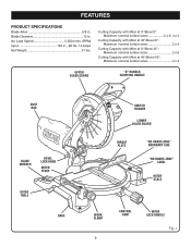
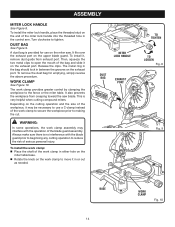
... sizes 2 x 6 Cutting Capacity with Miter at 45°/Bevel 45°: Maximum nominal lumber sizes 2 x 4 UPPER BLADE GUARD "D" HANDLE/ CARRYING HANDLE DUST BAG BLADE WRENCH BEVEL LOCK KNOB MITER FENCE MITER TABLE BASE SWITCH TRIGGER LOWER BLADE GUARD THROAT PLATE "NO HANDS ZONE" BOUNDARY LINE "NO HANDS ZONE" LABEL MITER SCALE WORK CLAMP 9 CONTROL ARM...
... sizes 2 x 6 Cutting Capacity with Miter at 45°/Bevel 45°: Maximum nominal lumber sizes 2 x 4 UPPER BLADE GUARD "D" HANDLE/ CARRYING HANDLE DUST BAG BLADE WRENCH BEVEL LOCK KNOB MITER FENCE MITER TABLE BASE SWITCH TRIGGER LOWER BLADE GUARD THROAT PLATE "NO HANDS ZONE" BOUNDARY LINE "NO HANDS ZONE" LABEL MITER SCALE WORK CLAMP 9 CONTROL ARM...
Operation Manual
Page 11
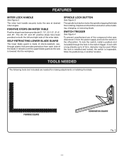
...176; and 45° positive stops have been provided at desired miter angles. The spindle lock button locks the spindle stopping the blade from the power supply and lock the switch in another location. FEATURES MITER LOCK HANDLE See Figure 2. The miter lock handle securely ...176;, and 45°. When the lock is installed and locked, the switch is lowered into the workpiece. SELF-RETRACTING LOWER BLADE GUARD The lower blade guard is made of shock-resistant, seethrough plastic that provides protection from each side of the compound miter saw is inoperable. It retracts...
...176; and 45° positive stops have been provided at desired miter angles. The spindle lock button locks the spindle stopping the blade from the power supply and lock the switch in another location. FEATURES MITER LOCK HANDLE See Figure 2. The miter lock handle securely ...176;, and 45°. When the lock is installed and locked, the switch is lowered into the workpiece. SELF-RETRACTING LOWER BLADE GUARD The lower blade guard is made of shock-resistant, seethrough plastic that provides protection from each side of the compound miter saw is inoperable. It retracts...
Operation Manual
Page 14
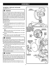
... the fence or the miter table. To install the miter lock handle, place the threaded stud on the upper blade guard. To install it may interfere with the blade guard prior to beginning any cutting operation to use on the work clamp assembly may be necessary to reduce the risk... of the blade guard assembly. It also prevents the workpiece from exhaust port. MITER LOCK HANDLE DUST BAG EXHAUST PORT TO TIGHTEN TO ...
... the fence or the miter table. To install the miter lock handle, place the threaded stud on the upper blade guard. To install it may interfere with the blade guard prior to beginning any cutting operation to use on the work clamp assembly may be necessary to reduce the risk... of the blade guard assembly. It also prevents the workpiece from exhaust port. MITER LOCK HANDLE DUST BAG EXHAUST PORT TO TIGHTEN TO ...
Operation Manual
Page 16
.... Rotate lower blade guard up and back to engage with the blade teeth and the arrow printed on the upper blade guard. Tighten blade bolt securely. Replace the lower blade guard and blade bolt cover. Replace blade bolt cover screw and tighten securely. Rotate blade bolt cover up and remove blade bolt cover screw. The blade teeth point downward...
.... Rotate lower blade guard up and back to engage with the blade teeth and the arrow printed on the upper blade guard. Tighten blade bolt securely. Replace the lower blade guard and blade bolt cover. Replace blade bolt cover screw and tighten securely. Rotate blade bolt cover up and remove blade bolt cover screw. The blade teeth point downward...
Operation Manual
Page 17
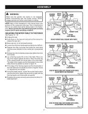
Never operate the saw . Never engage spindle lock button when blade is rotating. The edge of the square and the throat plate in the miter table should be parallel as shown in figure 15. If ... the saw arm. Raise saw into power source. NOTE: Many of the compound miter saw without all guards securely in place and in figures 16 and 17, adjustments are needed. Using the blade wrench, loosen the socket head screws securing the fence. Place one -half turn. Depress the miter...
Never operate the saw . Never engage spindle lock button when blade is rotating. The edge of the square and the throat plate in the miter table should be parallel as shown in figure 15. If ... the saw arm. Raise saw into power source. NOTE: Many of the compound miter saw without all guards securely in place and in figures 16 and 17, adjustments are needed. Using the blade wrench, loosen the socket head screws securing the fence. Place one -half turn. Depress the miter...


