Operation Manual
Page 1
Thank you years of rugged, trouble-free performance. SAVE THIS MANUAL FOR FUTURE REFERENCE When properly cared for, it will give you for dependability, ease of injury, the user must read and understand the operator's manual before using this product. Double Insulated Your miter saw has been engineered and manufactured to our high standard for your purchase. WARNING: To reduce the risk of operation, and operator safety. OPERATOR'S MANUAL 10 in. Compound Miter Saw TS1343L -
Thank you years of rugged, trouble-free performance. SAVE THIS MANUAL FOR FUTURE REFERENCE When properly cared for, it will give you for dependability, ease of injury, the user must read and understand the operator's manual before using this product. Double Insulated Your miter saw has been engineered and manufactured to our high standard for your purchase. WARNING: To reduce the risk of operation, and operator safety. OPERATOR'S MANUAL 10 in. Compound Miter Saw TS1343L -
Operation Manual
Page 4
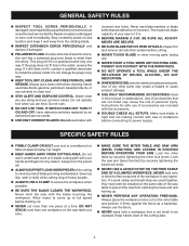
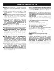
... AND GREASE. Do not reach underneath work clamp and length stop are defective or incorrect. Always use common sense. Never start the saw is tight and not making contact with incorrect size holes. Inspect for and remove all nails from the rotating blade. INSPECT...off. ALWAYS SUPPORT LONG WORKPIECES while cutting to a workbench or table at an authorized service facility. Use of personal injury. Lock the saw or workpiece before cutting. NEVER TOUCH BLADE or other moving parts during use. NEVER START A TOOL WHEN ANY ROTATING COMPONENT...
... AND GREASE. Do not reach underneath work clamp and length stop are defective or incorrect. Always use common sense. Never start the saw is tight and not making contact with incorrect size holes. Inspect for and remove all nails from the rotating blade. INSPECT...off. ALWAYS SUPPORT LONG WORKPIECES while cutting to a workbench or table at an authorized service facility. Use of personal injury. Lock the saw or workpiece before cutting. NEVER TOUCH BLADE or other moving parts during use. NEVER START A TOOL WHEN ANY ROTATING COMPONENT...
Operation Manual
Page 5
... the following markings: a) Wear eye protection. Do not allow familiarity (gained from the power source and have good balance. c) Do not operate saw ) to cause a careless mistake. Refer to them these instructions also. 5 g) Disconnect power (or unplug tool as applicable) before moving workpiece ...and use to avoid serious personal injury. SAVE THESE INSTRUCTIONS. This could cause your saw to a stable work surface. e) Never reach around saw . ALWAYS TURN OFF THE SAW before resuming operation. ALWAYS STAY ALERT! If you have damaged, missing, or failed ...
... the following markings: a) Wear eye protection. Do not allow familiarity (gained from the power source and have good balance. c) Do not operate saw ) to cause a careless mistake. Refer to them these instructions also. 5 g) Disconnect power (or unplug tool as applicable) before moving workpiece ...and use to avoid serious personal injury. SAVE THESE INSTRUCTIONS. This could cause your saw to a stable work surface. e) Never reach around saw . ALWAYS TURN OFF THE SAW before resuming operation. ALWAYS STAY ALERT! If you have damaged, missing, or failed ...
Operation Manual
Page 8
... to prevent kickback. Push Blocks (for narrow ripping operations. The aid helps keep the operator's hands well away from the blade. Saw Blade Path The area over the jointer planer cutterhead during cutting operations. Snipe (planers) Depression made at any operation. Worktable Surface where... (or strokes per minute), used to hold the workpiece during a ripping operation. GLOSSARY OF TERMS Anti-Kickback Pawls (radial arm and table saws) A device which, when properly installed and maintained, is designed to stop the workpiece from being kicked back toward operator. Dado Cut A...
... to prevent kickback. Push Blocks (for narrow ripping operations. The aid helps keep the operator's hands well away from the blade. Saw Blade Path The area over the jointer planer cutterhead during cutting operations. Snipe (planers) Depression made at any operation. Worktable Surface where... (or strokes per minute), used to hold the workpiece during a ripping operation. GLOSSARY OF TERMS Anti-Kickback Pawls (radial arm and table saws) A device which, when properly installed and maintained, is designed to stop the workpiece from being kicked back toward operator. Dado Cut A...
Operation Manual
Page 10
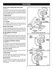
... ball bearings, and has externally accessible brushes for the blade wrench is included with all operating features and safety rules. 14 AMP MOTOR The saw arm by depressing the lock pin. LASER GUIDE For more accurate cuts, a laser guide is located in . It is packed with all cuts...and easy. MITER FENCE The miter fence on the tool and in this product, familiarize yourself with your miter saw . To transport, turn off and unplug the saw, then lower the saw . ELECTRIC BRAKE An electric brake has been provided to handle tough cutting jobs. These adjustment screws are attempting....
... ball bearings, and has externally accessible brushes for the blade wrench is included with all operating features and safety rules. 14 AMP MOTOR The saw arm by depressing the lock pin. LASER GUIDE For more accurate cuts, a laser guide is located in . It is packed with all cuts...and easy. MITER FENCE The miter fence on the tool and in this product, familiarize yourself with your miter saw . To transport, turn off and unplug the saw, then lower the saw . ELECTRIC BRAKE An electric brake has been provided to handle tough cutting jobs. These adjustment screws are attempting....
Operation Manual
Page 11
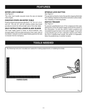
.... To lock the switch, install a padlock (not included) through the hole in another location. It retracts over the upper blade guard as the saw , disconnect it from each side of the miter table. SPINDLE LOCK BUTTON See Figure 3. Store the padlock key in the switch trigger. To prevent... from the power supply and lock the switch in . SELF-RETRACTING LOWER BLADE GUARD The lower blade guard is made of the compound miter saw is inoperable. The spindle lock button locks the spindle stopping the blade from rotating. Depress and hold the lock button while installing, changing,...
.... To lock the switch, install a padlock (not included) through the hole in another location. It retracts over the upper blade guard as the saw , disconnect it from each side of the miter table. SPINDLE LOCK BUTTON See Figure 3. Store the padlock key in the switch trigger. To prevent... from the power supply and lock the switch in . SELF-RETRACTING LOWER BLADE GUARD The lower blade guard is made of the compound miter saw is inoperable. The spindle lock button locks the spindle stopping the blade from rotating. Depress and hold the lock button while installing, changing,...
Operation Manual
Page 13
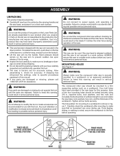
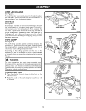
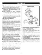
...: If any use . Any such alteration or modification is complete. Damage could result in figure 7. Four bolt holes have been provided in the saw base for mounting to a work surface before operating. machine bolts, lock washers, and hex nuts (not included). The hole pattern for this product...the top of the four mounting holes should be mounted to a workbench or an approved workstand. WARNING: Do not start the compound miter saw without checking for assistance. ALWAYS secure this list are damaged or missing, please call 1-800-525-2579 for interference between the blade and ...
...: If any use . Any such alteration or modification is complete. Damage could result in figure 7. Four bolt holes have been provided in the saw base for mounting to a work surface before operating. machine bolts, lock washers, and hex nuts (not included). The hole pattern for this product...the top of the four mounting holes should be mounted to a workbench or an approved workstand. WARNING: Do not start the compound miter saw without checking for assistance. ALWAYS secure this list are damaged or missing, please call 1-800-525-2579 for interference between the blade and ...
Operation Manual
Page 14
... guard prior to beginning any cutting operation to tighten. Then, squeeze the two metal clips to move it , remove dust guide from creeping toward the saw . MITER LOCK HANDLE DUST BAG EXHAUST PORT TO TIGHTEN TO LOOSEN Fig. 8 Fig. 9 BASE 14 WORK CLAMP Fig. 10 A dust bag is provided for emptying... of the work clamp in or out as needed. To install the work clamp: Place the shaft of the workpiece, it on the miter saw blade. To remove the dust bag for use a C-clamp instead of the work clamp assembly may be necessary to making the cut. Turn clockwise to...
... guard prior to beginning any cutting operation to tighten. Then, squeeze the two metal clips to move it , remove dust guide from creeping toward the saw . MITER LOCK HANDLE DUST BAG EXHAUST PORT TO TIGHTEN TO LOOSEN Fig. 8 Fig. 9 BASE 14 WORK CLAMP Fig. 10 A dust bag is provided for emptying... of the work clamp in or out as needed. To install the work clamp: Place the shaft of the workpiece, it on the miter saw blade. To remove the dust bag for use a C-clamp instead of the work clamp assembly may be necessary to making the cut. Turn clockwise to...
Operation Manual
Page 15
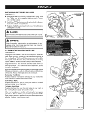
Avoid direct eye contact with using the Phillips end of the supplied blade wrench. Unplug the saw into the power source. Remove the padlock then plug the saw . Remove cover and set aside. Install two AAA batteries according to remove the mark. DANGER: Laser radiation. This line will let you in lining...
Avoid direct eye contact with using the Phillips end of the supplied blade wrench. Unplug the saw into the power source. Remove the padlock then plug the saw . Remove cover and set aside. Install two AAA batteries according to remove the mark. DANGER: Laser radiation. This line will let you in lining...
Operation Manual
Page 16
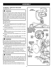
... blade bolt cover screw and tighten securely. Either of these situations could cause an accident since blade will not tighten properly. Fit saw . Turn blade bolt clockwise to tighten. The blade teeth point downward at the front of oil onto inner blade washer and outer blade washer...lower blade guard up and back to do so could result in a serious accident and can cause serious personal injury. Unplug the saw. Raise saw as shown in figure 14. Replace outer blade washer. Rotate blade bolt cover up and remove blade bolt cover screw. WARNING:...
... blade bolt cover screw and tighten securely. Either of these situations could cause an accident since blade will not tighten properly. Fit saw . Turn blade bolt clockwise to tighten. The blade teeth point downward at the front of oil onto inner blade washer and outer blade washer...lower blade guard up and back to do so could result in a serious accident and can cause serious personal injury. Unplug the saw. Raise saw as shown in figure 14. Replace outer blade washer. Rotate blade bolt cover up and remove blade bolt cover screw. WARNING:...
Operation Manual
Page 17
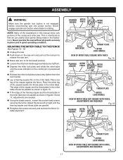
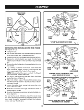
... THE MITER TABLE TO THE FENCE See Figures 15 - 18. Unplug the saw. Push down on the miter table. Place one -half turn. ...Release the miter lock plate and securely tighten the miter lock handle. Lay a framing square flat on the saw arm and pull out the lock pin to its full raised position. Loosen the miter lock handle approximately one... leg of the compound miter saw without all guards securely in place and in the miter table. This is intentional so that we can ...
... THE MITER TABLE TO THE FENCE See Figures 15 - 18. Unplug the saw. Push down on the miter table. Place one -half turn. ...Release the miter lock plate and securely tighten the miter lock handle. Lay a framing square flat on the saw arm and pull out the lock pin to its full raised position. Loosen the miter lock handle approximately one... leg of the compound miter saw without all guards securely in place and in the miter table. This is intentional so that we can ...
Operation Manual
Page 18
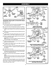
...After squaring adjustments have been made, it may be parallel as shown in figure 19. If the front or back edge of the saw blade angles away from the square as shown in transport position. Loosen the miter lock handle approximately one-half turn. Depress ...the miter lock plate and rotate the miter table until the saw blade is positioned at 0°. Release the miter lock plate and securely tighten the miter lock handle. Lay a framing square flat ...
...After squaring adjustments have been made, it may be parallel as shown in figure 19. If the front or back edge of the saw blade angles away from the square as shown in transport position. Loosen the miter lock handle approximately one-half turn. Depress ...the miter lock plate and rotate the miter table until the saw blade is positioned at 0°. Release the miter lock plate and securely tighten the miter lock handle. Lay a framing square flat ...
Operation Manual
Page 19
...is positioned at 0°. Release the miter lock plate and securely tighten the miter lock handle. Loosen bevel lock knob and set saw arm at 0° bevel (blade set 90° to -table alignment. NOTE: The above procedure can be necessary to loosen the indicator screws ...0° and 45° angles. Tighten bevel lock knob. Place a combination square against the miter table and the flat part of the saw blade angles away from the square as shown in the Adjustment section. Retighten bevel lock knob. NOTE: Make sure that the square contacts the...
...is positioned at 0°. Release the miter lock plate and securely tighten the miter lock handle. Loosen bevel lock knob and set saw arm at 0° bevel (blade set 90° to -table alignment. NOTE: The above procedure can be necessary to loosen the indicator screws ...0° and 45° angles. Tighten bevel lock knob. Place a combination square against the miter table and the flat part of the saw blade angles away from the square as shown in the Adjustment section. Retighten bevel lock knob. NOTE: Make sure that the square contacts the...
Operation Manual
Page 20
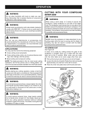
...Do not use one side of the accessory blades available from blade. Any slip can result in serious personal injury. Never operate the miter saw arm to secure the workpiece, clamp workpiece on the floor or in workpiece. WARNING: Before starting any cutting operation freehand (without holding workpiece...miter table set at some angle other than zero. Pull out the lock pin and lift saw on one of the blade only. from the Ryobi dealer. CUTTING WITH YOUR COMPOUND MITER SAW WARNING: When using a work clamp or C-clamp to its full height. Loosen the miter ...
...Do not use one side of the accessory blades available from blade. Any slip can result in serious personal injury. Never operate the miter saw arm to secure the workpiece, clamp workpiece on the floor or in workpiece. WARNING: Before starting any cutting operation freehand (without holding workpiece...miter table set at some angle other than zero. Pull out the lock pin and lift saw on one of the blade only. from the Ryobi dealer. CUTTING WITH YOUR COMPOUND MITER SAW WARNING: When using a work clamp or C-clamp to its full height. Loosen the miter ...
Operation Manual
Page 21
... See Figure 31. Align cutting line on the workpiece with the miter table. NOTE: Quickly locate zero by cutting across the grain of saw arm has been set from the miter table. See Figure 31. Align the cutting line on workpiece with edge of the workpiece with the..., place the convex side against the fence. The lock plate will occur when the cut . Loosen the bevel lock knob and move the saw , perform a dry run of the cutting operation just to stop notches, located in one of the positive stop rotating before removing the workpiece from 0&#...
... See Figure 31. Align cutting line on the workpiece with the miter table. NOTE: Quickly locate zero by cutting across the grain of saw arm has been set from the miter table. See Figure 31. Align the cutting line on workpiece with edge of the workpiece with the..., place the convex side against the fence. The lock plate will occur when the cut . Loosen the bevel lock knob and move the saw , perform a dry run of the cutting operation just to stop notches, located in one of the positive stop rotating before removing the workpiece from 0&#...
Operation Manual
Page 22
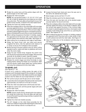
... the control arm until the electric brake stops blade from turning before removing the workpiece from 0° to 45°. Once the saw handle firmly. Once the two correct settings for certain roof framing cuts. OPERATION Grasp the stock firmly with one another. Adjustments of ...knob. Recheck miter angle setting. COMPOUND MITER CUT WORK CLAMP Fig. 29 Loosen the bevel lock knob and move the saw blade. 22 Depress the switch lock with the edge of workpiece. Wait until the pointer aligns with sloping sides, and for a particular cut...
... the control arm until the electric brake stops blade from turning before removing the workpiece from 0° to 45°. Once the saw handle firmly. Once the two correct settings for certain roof framing cuts. OPERATION Grasp the stock firmly with one another. Adjustments of ...knob. Recheck miter angle setting. COMPOUND MITER CUT WORK CLAMP Fig. 29 Loosen the bevel lock knob and move the saw blade. 22 Depress the switch lock with the edge of workpiece. Wait until the pointer aligns with sloping sides, and for a particular cut...
Operation Manual
Page 23
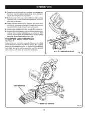
... placed along the workpiece so it against the fence. Wait until the electric brake stops blade from turning before raising the blade out of the saw blade to secure the workpiece. 45° X 45° COMPOUND MITER CUT Fig. 30 LONG WORKPIECE 0 WORKPIECE SUPPORTS 23 Fig. 31 Supports should let the... workpiece lay flat on the saw, perform a dry run of the cutting operation just to make sure that no problems will occur when the cut is made. Grasp the...
... placed along the workpiece so it against the fence. Wait until the electric brake stops blade from turning before raising the blade out of the saw blade to secure the workpiece. 45° X 45° COMPOUND MITER CUT Fig. 30 LONG WORKPIECE 0 WORKPIECE SUPPORTS 23 Fig. 31 Supports should let the... workpiece lay flat on the saw, perform a dry run of the cutting operation just to make sure that no problems will occur when the cut is made. Grasp the...
Operation Manual
Page 25
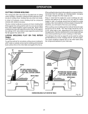
...crown molding. LAYING MOLDING FLAT ON THE MITER TABLE See Figure 32. See the chart below for the application. In general, compound miter saws do not have angles of crown molding on the desired cut for correct angle settings and correct positioning of exactly 90°, therefore, ... to shift, all settings should be tested on the miter table and against the ceiling) of 38°. OPERATION CUTTING CROWN MOLDING The compound miter saw . 52° 38° CEILING W A L L FENCE INSIDE CORNER TOP EDGE AGAINST FENCE = LEFT SIDE, INSIDE CORNER RIGHT SIDE, OUTSIDE CORNER MITER ...
...crown molding. LAYING MOLDING FLAT ON THE MITER TABLE See Figure 32. See the chart below for the application. In general, compound miter saws do not have angles of crown molding on the desired cut for correct angle settings and correct positioning of exactly 90°, therefore, ... to shift, all settings should be tested on the miter table and against the ceiling) of 38°. OPERATION CUTTING CROWN MOLDING The compound miter saw . 52° 38° CEILING W A L L FENCE INSIDE CORNER TOP EDGE AGAINST FENCE = LEFT SIDE, INSIDE CORNER RIGHT SIDE, OUTSIDE CORNER MITER ...
Operation Manual
Page 27
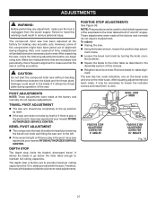
... been adjusted at your nearest RYOBI AUTHORIZED SERVICE CENTER. It allows the blade to go below the miter table enough to -table alignment. blade provided with blade provided should never need adjustments. Therefore, the saw with the saw. NOTE: This procedure can be necessary to loosen the ...to check blade squareness of the components might have saw repaired at the factory for interference between the blade and the throat plate. DEPTH STOP The depth stop is play in the pivot, have been made at your nearest RYOBI AUTHORIZED SERVICE CENTER. The depth stop limits the...
... been adjusted at your nearest RYOBI AUTHORIZED SERVICE CENTER. It allows the blade to go below the miter table enough to -table alignment. blade provided with blade provided should never need adjustments. Therefore, the saw with the saw. NOTE: This procedure can be necessary to loosen the ...to check blade squareness of the components might have saw repaired at the factory for interference between the blade and the throat plate. DEPTH STOP The depth stop is play in the pivot, have been made at your nearest RYOBI AUTHORIZED SERVICE CENTER. The depth stop limits the...
Operation Manual
Page 28
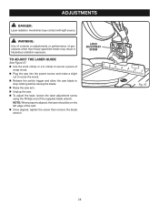
... wrench. TO ADJUST THE LASER GUIDE See Figure 37. Use the work clamp or a C-clamp to secure a piece of scrap wood. Plug the saw into the power source and make a slight cut to score the wood. Release the switch trigger and allow the... saw blade to stop rotating before raising the blade. Raise the saw arm. Unplug the saw. To adjust the laser, loosen the laser adjustment screw using the Phillips end of the supplied blade...
... wrench. TO ADJUST THE LASER GUIDE See Figure 37. Use the work clamp or a C-clamp to secure a piece of scrap wood. Plug the saw into the power source and make a slight cut to score the wood. Release the switch trigger and allow the... saw blade to stop rotating before raising the blade. Raise the saw arm. Unplug the saw. To adjust the laser, loosen the laser adjustment screw using the Phillips end of the supplied blade...


