
English Manual
Page 1
... committed to providing complete customer satisfaction. Visit our website at www.proform.com new products, prizes, fitness tips, and much more! Write the serial number in this manual before using this manual for future reference. Serial Number Decal (Under Seat) QUESTIONS? Model No. Save this equipment. If you have questions, or if a part is damaged or missing, PLEASE CONTACT OUR CUSTOMER SERVICE DEPARTMENT DIRECTLY.
... committed to providing complete customer satisfaction. Visit our website at www.proform.com new products, prizes, fitness tips, and much more! Write the serial number in this manual before using this manual for future reference. Serial Number Decal (Under Seat) QUESTIONS? Model No. Save this equipment. If you have questions, or if a part is damaged or missing, PLEASE CONTACT OUR CUSTOMER SERVICE DEPARTMENT DIRECTLY.
English Manual
Page 2
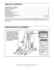
... decal in the center of ICON IP, Inc. 2 PROFORM is missing or illegible, call the toll-free telephone number on the weight system. TABLE OF CONTENTS WARNING DECAL PLACEMENT 2 IMPORTANT PRECAUTIONS 3 BEFORE YOU BEGIN 4 ASSEMBLY 5 ADJUSTMENTS 13 WEIGHT RESISTANCE CHART 17 CABLE DIAGRAM 17 EXERCISE GUIDELINES 18 ORDERING REPLACEMENT PARTS Back Cover LIMITED WARRANTY Back Cover Note: A PART IDENTIFICATION CHART and a PART LIST/EXPLODED DRAWING are attached in the location shown. WARNING DECAL PLACEMENT The...
... decal in the center of ICON IP, Inc. 2 PROFORM is missing or illegible, call the toll-free telephone number on the weight system. TABLE OF CONTENTS WARNING DECAL PLACEMENT 2 IMPORTANT PRECAUTIONS 3 BEFORE YOU BEGIN 4 ASSEMBLY 5 ADJUSTMENTS 13 WEIGHT RESISTANCE CHART 17 CABLE DIAGRAM 17 EXERCISE GUIDELINES 18 ORDERING REPLACEMENT PARTS Back Cover LIMITED WARRANTY Back Cover Note: A PART IDENTIFICATION CHART and a PART LIST/EXPLODED DRAWING are attached in the location shown. WARNING DECAL PLACEMENT The...
English Manual
Page 3
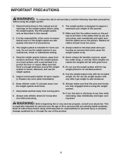
..., and use only. Do not use the weight system with any time while exercising, stop immediately and make sure that all times. Replace any commercial, rental, or institutional setting. 11. Do not use of this manual. 2. ICON assumes no responsibility for home use the weight system. 5. the weights will fall with a mat beneath it to support a maximum user weight of 300 pounds. 10. If you are exercising, stop immediately...
..., and use only. Do not use the weight system with any time while exercising, stop immediately and make sure that all times. Replace any commercial, rental, or institutional setting. 11. Do not use of this manual. 2. ICON assumes no responsibility for home use the weight system. 5. the weights will fall with a mat beneath it to support a maximum user weight of 300 pounds. 10. If you are exercising, stop immediately...
English Manual
Page 4
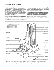
... parts that are determined relative to tone your body, build dramatic muscle size and strength, or improve your benefit, read this manual). The model number is to a person sitting on the drawings in . (165 cm) Backrest Press Arm Knob Press Arm Right Side Curl Pad Seat Pulley Housing Leg Developer Base Squat Bar Dip Handle Dip Arm Knob Dip Arm Dip Arm Pin Weight Weight Pin Locking Caster Left Side Extension Strap Handle Curl Bar...
... parts that are determined relative to tone your body, build dramatic muscle size and strength, or improve your benefit, read this manual). The model number is to a person sitting on the drawings in . (165 cm) Backrest Press Arm Knob Press Arm Right Side Curl Pad Seat Pulley Housing Leg Developer Base Squat Bar Dip Handle Dip Arm Knob Dip Arm Dip Arm Pin Weight Weight Pin Locking Caster Left Side Extension Strap Handle Curl Bar...
English Manual
Page 5
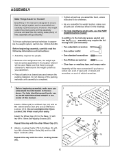
...; Place all parts are oriented as you assemble them, unless instructed to a Wheel Cap (31) with an M8 x 65mm Button Bolt (94) and an M8 Nylon Locknut (110). Attach a Locking Caster (76) to walk around the weight system as shown in the drawings. • For help identifying small parts, use the PART IDENTIFICATION CHART. For help identifying small parts, use the PART IDENTIFICATION CHART in the...
...; Place all parts are oriented as you assemble them, unless instructed to a Wheel Cap (31) with an M8 x 65mm Button Bolt (94) and an M8 Nylon Locknut (110). Attach a Locking Caster (76) to walk around the weight system as shown in the drawings. • For help identifying small parts, use the PART IDENTIFICATION CHART. For help identifying small parts, use the PART IDENTIFICATION CHART in the...

English Manual
Page 6
... M4 x 13mm Self-tapping Screw (112). If the Press Arm Cable (not shown) is preattached, make sure that the Bolt is com- the Dip Arm must pivot easily. Attach the Dip Arm Pin (53) to the Base with the Bolt and an M10 Nylon Locknut (108). Do not tighten the Nylon Locknuts yet. 108 108 1 4. Note: The parts in steps 7, 13, and 14...
... M4 x 13mm Self-tapping Screw (112). If the Press Arm Cable (not shown) is preattached, make sure that the Bolt is com- the Dip Arm must pivot easily. Attach the Dip Arm Pin (53) to the Base with the Bolt and an M10 Nylon Locknut (108). Do not tighten the Nylon Locknuts yet. 108 108 1 4. Note: The parts in steps 7, 13, and 14...

English Manual
Page 7
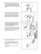
... Press Arm Cable (not shown) has been routed through the Top Cover (24), make sure that the Pin is underneath the Weight and is completed. Insert the Weight Tube (16) into the top hole in the Weight Tube. Slide eleven Weights (27) onto the Weight Guides. Slide the Weight (27) onto the Weight Guides (13). 6. Attach the Top Frame (12) to the Upright (3) with 5 an M10 x 50mm Bolt...
... Press Arm Cable (not shown) has been routed through the Top Cover (24), make sure that the Pin is underneath the Weight and is completed. Insert the Weight Tube (16) into the top hole in the Weight Tube. Slide eleven Weights (27) onto the Weight Guides. Slide the Weight (27) onto the Weight Guides (13). 6. Attach the Top Frame (12) to the Upright (3) with 5 an M10 x 50mm Bolt...

English Manual
Page 8
... 8. 7. Make sure that the Cable Trap is routed around the pulleys above the Press Arm as shown in the groove of the Pulley. 12 66 47 43 97 9. Route the Press Arm Cable (66) through the Press Arm. Refer to the CABLE DIAGRAM on page 17 to 7 ensure correct cable routing during steps 7 through 14. 66 Use the wire in the Left Press Arm (7) to hold the Cable in the groove of...
... 8. 7. Make sure that the Cable Trap is routed around the pulleys above the Press Arm as shown in the groove of the Pulley. 12 66 47 43 97 9. Route the Press Arm Cable (66) through the Press Arm. Refer to the CABLE DIAGRAM on page 17 to 7 ensure correct cable routing during steps 7 through 14. 66 Use the wire in the Left Press Arm (7) to hold the Cable in the groove of...
English Manual
Page 9
... Press Arm Cable (66) down through the Top 12 Cover (24) and over the Press Arm Cable (66). Tighten four M6 x 10mm Set Screws (114) into the Cable Coupler (64). Use the wire in the groove of the Pulley. 47 43 97 66 12 12. Make sure that the Cable Trap is routed around the pulleys above the Press Arm as shown and slide it 14 onto the Press Arm Cable (66). Attach...
... Press Arm Cable (66) down through the Top 12 Cover (24) and over the Press Arm Cable (66). Tighten four M6 x 10mm Set Screws (114) into the Cable Coupler (64). Use the wire in the groove of the Pulley. 47 43 97 66 12 12. Make sure that the Cable Trap is routed around the pulleys above the Press Arm as shown and slide it 14 onto the Press Arm Cable (66). Attach...
English Manual
Page 11
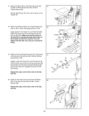
... Seat Frame (4) with the Bolt Set. Make sure that the barrel of the Dip Arm (5). 19 10 33 51 5 102 35 34 102 20. Do not overtighten the Bolt Set; Repeat this step on the Upright (3). 4 3 18. 17. Attach a Front and Rear Dip Cap (33, 34) around a Dip Handle (10) with two M6 x 70mm Screws (93). Repeat this step on the Front Leg...
... Seat Frame (4) with the Bolt Set. Make sure that the barrel of the Dip Arm (5). 19 10 33 51 5 102 35 34 102 20. Do not overtighten the Bolt Set; Repeat this step on the Upright (3). 4 3 18. 17. Attach a Front and Rear Dip Cap (33, 34) around a Dip Handle (10) with two M6 x 70mm Screws (93). Repeat this step on the Front Leg...

English Manual
Page 13
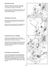
... ADJUSTING THE PRESS ARM above). Move the Dip Arm to the desired position, and reengage the Knob into the Adjustment Plate (25). Properly tighten all parts each exercise. Reengage the Dip Arm Knob into the Upright (3) and the Dip Arm. 13 5 3 53 Then, remove the Dip Arm Pin (53). Move the Press Arm to the raised or lowered position. See the EXERCISE GUIDELINES on page 18 for each time the weight system is used. Replace...
... ADJUSTING THE PRESS ARM above). Move the Dip Arm to the desired position, and reengage the Knob into the Adjustment Plate (25). Properly tighten all parts each exercise. Reengage the Dip Arm Knob into the Upright (3) and the Dip Arm. 13 5 3 53 Then, remove the Dip Arm Pin (53). Move the Press Arm to the raised or lowered position. See the EXERCISE GUIDELINES on page 18 for each time the weight system is used. Replace...
English Manual
Page 14
... the exercise. 3 19 4 Post ATTACHING THE CURL PAD To use the Leg Developer (6), first move the press arms to the lowered position (see ATTACHING THE PULLEY HOUSINGS above). ATTACHING THE LEG DEVELOPER To use the Curl Pad (20), insert the Curl Post (9) into the Seat Frame (4). Then, attach the pulley housings to the Leg Developer using a Clip (61). Then, attach the Housing Cables (71) to the leg developer position (see ADJUSTING THE PRESS ARM...
... the exercise. 3 19 4 Post ATTACHING THE CURL PAD To use the Leg Developer (6), first move the press arms to the lowered position (see ATTACHING THE PULLEY HOUSINGS above). ATTACHING THE LEG DEVELOPER To use the Curl Pad (20), insert the Curl Post (9) into the Seat Frame (4). Then, attach the pulley housings to the Leg Developer using a Clip (61). Then, attach the Housing Cables (71) to the leg developer position (see ADJUSTING THE PRESS ARM...

English Manual
Page 15
...). Finally, attach the Curl Bar to the Leg Developer with a Clip (61). 58 6 71 61 ATTACHING THE SQUAT BAR To use the Curl Bar (58), first attach the curl pad to a Housing Cable (not shown), with two Clips. Next, attach the Squat Bar to the correct length. Adjust the Extension Strap to the Housing Cables (71) with two Clips (not shown). Next, attach the pulley housings...
...). Finally, attach the Curl Bar to the Leg Developer with a Clip (61). 58 6 71 61 ATTACHING THE SQUAT BAR To use the Curl Bar (58), first attach the curl pad to a Housing Cable (not shown), with two Clips. Next, attach the Squat Bar to the correct length. Adjust the Extension Strap to the Housing Cables (71) with two Clips (not shown). Next, attach the pulley housings...
English Manual
Page 16
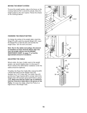
.... Lever 76 CHANGING THE WEIGHT SETTING To change the setting of resistance. To tighten the Press Arm Cable (66), remove the M10 x 50mm Bolt (96) from the weight setting. Use the WEIGHT RESISTANCE CHART on page 17 to the cables and pulleys, the amount of cable used on the Locking Casters. ADJUSTING THE CABLE Woven cable, the type of resistance at each exercise station may vary from the Weight Tube (16). To loosen the Cable, attach the Pulley to a lower hole in...
.... Lever 76 CHANGING THE WEIGHT SETTING To change the setting of resistance. To tighten the Press Arm Cable (66), remove the M10 x 50mm Bolt (96) from the weight setting. Use the WEIGHT RESISTANCE CHART on page 17 to the cables and pulleys, the amount of cable used on the Locking Casters. ADJUSTING THE CABLE Woven cable, the type of resistance at each exercise station may vary from the Weight Tube (16). To loosen the Cable, attach the Pulley to a lower hole in...

English Manual
Page 17
... *The weight resistance shown is for the 12.5 lb. CABLE DIAGRAM The cable diagram shows the proper routing of the Press Arm Cable (66). The numbers show the correct route for the Cable. Make sure that the Cable and the cable traps have been assembled correctly. weights. Use the diagram to differences in individual weight plates and friction between the cables, pulleys, and weight guides. If the Cable has not been correctly routed, the weight system will...
... *The weight resistance shown is for the 12.5 lb. CABLE DIAGRAM The cable diagram shows the proper routing of the Press Arm Cable (66). The numbers show the correct route for the Cable. Make sure that the Cable and the cable traps have been assembled correctly. weights. Use the diagram to differences in individual weight plates and friction between the cables, pulleys, and weight guides. If the Cable has not been correctly routed, the weight system will...
English Manual
Page 18
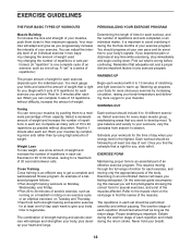
... fitness program. Exercising in any time while exercising, stop immediately and begin cooling down. You must gauge your body time to 10 different exercises. Rest for you find the names of aerobic exercise, such as possible without difficulty, increase the amount of strength training and aerobic exercise will adapt and grow as you want to your heart and lungs. Weight Loss To lose weight, use...
... fitness program. Exercising in any time while exercising, stop immediately and begin cooling down. You must gauge your body time to 10 different exercises. Rest for you find the names of aerobic exercise, such as possible without difficulty, increase the amount of strength training and aerobic exercise will adapt and grow as you want to your heart and lungs. Weight Loss To lose weight, use...

English Manual
Page 19
...exercise. Record your weight and key body measurements at the end of each workout is to increase flexibility. Brachioradials (forearm) F. Hip Flexors (upper thigh) G. Gastrocnemius (back of thigh) J. Remember, the key to achieving the greatest results is an effective way to make exercise a regular and enjoyable part of your arms and legs...set for a muscle building workout. • Rest for one minute after each set. List the date, the exercises performed, the resistance used, and the numbers of arm) S. Rest for a short period of time after each set for a toning work...
...exercise. Record your weight and key body measurements at the end of each workout is to increase flexibility. Brachioradials (forearm) F. Hip Flexors (upper thigh) G. Gastrocnemius (back of thigh) J. Remember, the key to achieving the greatest results is an effective way to make exercise a regular and enjoyable part of your arms and legs...set for a muscle building workout. • Rest for one minute after each set. List the date, the exercises performed, the resistance used, and the numbers of arm) S. Rest for a short period of time after each set for a toning work...

English Manual
Page 20
... Front Dip Cap Rear Dip Cap Dip Arm Bushing Bumper 57mm Round Inner Cap Leg Developer Cap 89mm Round Cap Press Arm Cap Trunnion 4" Pulley 3 1/2" Pulley 2 3/4" Pulley 45mm x 3mm Spacer Finger Guard Cable Trap Half Guard M12 Locknut Press Arm Knob Dip Arm Knob Curl Knob Dip Arm Pin Pulley Housing Squat Bar Bar Grip 32mm Round Inner Cap Curl Bar Ankle Strap 19mm Square Inner Cap Clip Weight Tube Bumper Key Qty. PART LIST-Model No.
... Front Dip Cap Rear Dip Cap Dip Arm Bushing Bumper 57mm Round Inner Cap Leg Developer Cap 89mm Round Cap Press Arm Cap Trunnion 4" Pulley 3 1/2" Pulley 2 3/4" Pulley 45mm x 3mm Spacer Finger Guard Cable Trap Half Guard M12 Locknut Press Arm Knob Dip Arm Knob Curl Knob Dip Arm Pin Pulley Housing Squat Bar Bar Grip 32mm Round Inner Cap Curl Bar Ankle Strap 19mm Square Inner Cap Clip Weight Tube Bumper Key Qty. PART LIST-Model No.
English Manual
Page 21
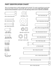
...) M6 x 70mm Screw (93) 2.5" Bolt Set (86) M6 x 100mm Screw (85) M6 x 10mm Set Screw (114) M10 x 100mm Button Bolt (91) M6 x 115mm Screw (113) M10 x 115mm Bolt (84) The number in parentheses by each drawing is not in the parts bag, check to identify small parts used in the center of the part, from the PART LIST in assembly. If a part is the key number of this manual. PART IDENTIFICATION CHART Refer to...
...) M6 x 70mm Screw (93) 2.5" Bolt Set (86) M6 x 100mm Screw (85) M6 x 10mm Set Screw (114) M10 x 100mm Button Bolt (91) M6 x 115mm Screw (113) M10 x 115mm Bolt (84) The number in parentheses by each drawing is not in the parts bag, check to identify small parts used in the center of the part, from the PART LIST in assembly. If a part is the key number of this manual. PART IDENTIFICATION CHART Refer to...
English Manual
Page 24
... (PROFORM FUSION 6.5 LX weight system) • the SERIAL NUMBER of the product (see the front cover of this manual) • the KEY NUMBER and DESCRIPTION of the part(s) (see the front cover of this product to the original purchaser. To help us assist you specific legal rights. ORDERING REPLACEMENT PARTS To order replacement parts, please see the PART LIST and EXPLODED DRAWING in the center of this manual) LIMITED WARRANTY ICON Health & Fitness, Inc. (ICON) warrants...
... (PROFORM FUSION 6.5 LX weight system) • the SERIAL NUMBER of the product (see the front cover of this manual) • the KEY NUMBER and DESCRIPTION of the part(s) (see the front cover of this product to the original purchaser. To help us assist you specific legal rights. ORDERING REPLACEMENT PARTS To order replacement parts, please see the PART LIST and EXPLODED DRAWING in the center of this manual) LIMITED WARRANTY ICON Health & Fitness, Inc. (ICON) warrants...


