
English Manual
Page 1
® Model No. Write the serial number in the location shown below. MST CAUTION Read all precautions and instructions in this manual before using this manual for future reference. If you have questions or if there are missing parts, we are committed to you. The serial number is found in the space above. TO AVOID UNNECESSARY DELAYS, PLEASE CALL DIRECT TO OUR TOLL-FREE CUSTOMER...
® Model No. Write the serial number in the location shown below. MST CAUTION Read all precautions and instructions in this manual before using this manual for future reference. If you have questions or if there are missing parts, we are committed to you. The serial number is found in the space above. TO AVOID UNNECESSARY DELAYS, PLEASE CALL DIRECT TO OUR TOLL-FREE CUSTOMER...
English Manual
Page 2
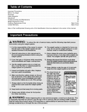
... any worn parts immediately. 6. ICON assumes no responsibility for home use these attachments. 13. Read all precautions. 2. Use the weight system only on the front cover of this manual. Always wear athletic shoes for protection. 5. Table of Contents Important Precautions ...2 Before You Begin ...3 Assembly ...4 Cable Diagrams ...22 Adjustment ...24 Trouble-shooting and Maintenance ...25 Weight Resistance Chart ...27 Ordering Replacement Parts ...Back Cover Limited Warranty ...Back Cover Note: A Part List/Exploded Drawing and a Part Identification Chart are raised...
... any worn parts immediately. 6. ICON assumes no responsibility for home use these attachments. 13. Read all precautions. 2. Use the weight system only on the front cover of this manual. Always wear athletic shoes for protection. 5. Table of Contents Important Precautions ...2 Before You Begin ...3 Assembly ...4 Cable Diagrams ...22 Adjustment ...24 Trouble-shooting and Maintenance ...25 Weight Resistance Chart ...27 Ordering Replacement Parts ...Back Cover Limited Warranty ...Back Cover Note: A Part List/Exploded Drawing and a Part Identification Chart are raised...
English Manual
Page 3
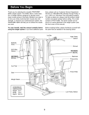
... the front cover of the body. Lat Bar High Pulley Station Butterfly Arms Shroud Ab Pulley Station WARNING DECAL Backrest Press Arms WARNING DECAL Curl Pad Seat Press Plate Weight Stack ASSEMBLED DIMENSIONS: Height: 75 in . Width: 78 in . The serial number can be found on a decal attached to develop every major muscle group of this manual carefully before calling. Low Pulley Station 3 Mountain Time (excluding holidays). The model number is...
... the front cover of the body. Lat Bar High Pulley Station Butterfly Arms Shroud Ab Pulley Station WARNING DECAL Backrest Press Arms WARNING DECAL Curl Pad Seat Press Plate Weight Stack ASSEMBLED DIMENSIONS: Height: 75 in . Width: 78 in . The serial number can be found on a decal attached to develop every major muscle group of this manual carefully before calling. Low Pulley Station 3 Mountain Time (excluding holidays). The model number is...
English Manual
Page 4
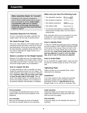
...: Some small parts may want to easily identify parts during each stage are exercising. The parts needed for that you operate while you have a socket set, a set of its weight and size, the weight system should be assembled in assembly, we have included a PART IDENTIFICATION CHART in the drawings. Arm Assembly Next you will assemble the seats and backrests. 4 Seat Assembly During this brief introduction will also need grease or petroleum jelly...
...: Some small parts may want to easily identify parts during each stage are exercising. The parts needed for that you operate while you have a socket set, a set of its weight and size, the weight system should be assembled in assembly, we have included a PART IDENTIFICATION CHART in the drawings. Arm Assembly Next you will assemble the seats and backrests. 4 Seat Assembly During this brief introduction will also need grease or petroleum jelly...

English Manual
Page 5
...locations on the Weight Base (5). 1 28 28 4 85 92 92 5 28 28 Insert four 5/16" x 2 1/2" Carriage Bolts (92) and a 3/8" x 3 3/4" Carriage Bolt (85) into each end of each end of the Press Base (6). Insert four 5/16" x 2 1/2" Carriage Bolts (92) and a 3/8" x 4" Carriage Bolt (104) into each Bolt. 2. Note: The 3/8" x 4" Carriage Bolt...make sure that you have read and understood the information on the floor. Open the parts bag labeled "FRAME ASSEMBLY." Attach the Weight Base (5) to the Weight Base (5) with two 5/16" x 2 3/4" Bolts (89), a Support Plate (94), and two 5/16" Nylon ...
...locations on the Weight Base (5). 1 28 28 4 85 92 92 5 28 28 Insert four 5/16" x 2 1/2" Carriage Bolts (92) and a 3/8" x 3 3/4" Carriage Bolt (85) into each end of each end of the Press Base (6). Insert four 5/16" x 2 1/2" Carriage Bolts (92) and a 3/8" x 4" Carriage Bolt (104) into each Bolt. 2. Note: The 3/8" x 4" Carriage Bolt...make sure that you have read and understood the information on the floor. Open the parts bag labeled "FRAME ASSEMBLY." Attach the Weight Base (5) to the Weight Base (5) with two 5/16" x 2 3/4" Bolts (89), a Support Plate (94), and two 5/16" Nylon ...

English Manual
Page 7
... 1 7 Press three 2" Square Inner Caps (28) into the lower end of the holes. Slide the Weight Tube into each Upright (1, 2) with two 3/8" x 2 3/4" Bolts (46), a Small Support Plate (26), and two 3/8" Nylon Locknuts (50). Note: When attaching the Weight Top Frame make sure that the tops of the Nylon Locknuts (64) used in it. Slide twelve Weights (21) onto the Weight Guides (15). Tighten...
... 1 7 Press three 2" Square Inner Caps (28) into the lower end of the holes. Slide the Weight Tube into each Upright (1, 2) with two 3/8" x 2 3/4" Bolts (46), a Small Support Plate (26), and two 3/8" Nylon Locknuts (50). Note: When attaching the Weight Top Frame make sure that the tops of the Nylon Locknuts (64) used in it. Slide twelve Weights (21) onto the Weight Guides (15). Tighten...

English Manual
Page 9
... (64) used in steps 13 and 14. 14 36 89 3 28 64 14 64 64 4 92 15. 14. Attach the Press Front Leg to the Butterfly Seat Frame (14) with a 1" Tap Screw (80). Attach the Press Seat Frame (7) to the Butterfly Front Leg (3) with the welded rod in the Press Base (6). Hand tighten two 5/16" Nylon Locknuts (64) onto the Bolts. Do not tighten the...
... (64) used in steps 13 and 14. 14 36 89 3 28 64 14 64 64 4 92 15. 14. Attach the Press Front Leg to the Butterfly Seat Frame (14) with a 1" Tap Screw (80). Attach the Press Seat Frame (7) to the Butterfly Front Leg (3) with the welded rod in the Press Base (6). Hand tighten two 5/16" Nylon Locknuts (64) onto the Bolts. Do not tighten the...

English Manual
Page 11
... pages 22 and 23. Attach the "V"-Pulley and a Large Cable Trap (32) to the welded bracket (see the inset drawing) on the Bolt. 22. Wrap the Butterfly Cable (73) around the pulleys exactly as shown in the direction shown. Cable Assembly 21. For cable identification and routing during steps 21 to 52, refer to the Cable Diagram and Cable ID Chart on the back of the...
... pages 22 and 23. Attach the "V"-Pulley and a Large Cable Trap (32) to the welded bracket (see the inset drawing) on the Bolt. 22. Wrap the Butterfly Cable (73) around the pulleys exactly as shown in the direction shown. Cable Assembly 21. For cable identification and routing during steps 21 to 52, refer to the Cable Diagram and Cable ID Chart on the back of the...

English Manual
Page 12
...). Attach the Pulley and a Cable Trap (25) to the bracket on the Upright. 26 63 48 47 24 74 Welded Pin 1 47 Large Tabs 48 59 27. the Cable must pivot freely on the other. Wrap the Ab Cable (74) around a 3 1/2" Pulley (24) in the position shown. Remove both 3 1/2" Pulleys (24) from the second set of pre-assembled Pulley Plates (23). Place two Pulley Covers...
...). Attach the Pulley and a Cable Trap (25) to the bracket on the Upright. 26 63 48 47 24 74 Welded Pin 1 47 Large Tabs 48 59 27. the Cable must pivot freely on the other. Wrap the Ab Cable (74) around a 3 1/2" Pulley (24) in the position shown. Remove both 3 1/2" Pulleys (24) from the second set of pre-assembled Pulley Plates (23). Place two Pulley Covers...

English Manual
Page 14
...Attach the Pulley and a Cable Trap (25) to the lower hole in the second set of the Ab Cable (74) to the hole in the Short Weight Tube (17) with a 3/8" x 2" Bolt (54) and a 3/8" Nylon Locknut (50). Make sure the Cable Trap is oriented as shown. 34 Bracket 54 4 25 75 24 50 Cable Guide 35. Attach...Base (4) with a 3/8" x 5" Bolt (108) and a hand tightened 3/8" Nylon Locknut (50) as shown. 36 23 75 24 25 54 50 14 Attach the Pulley and a Cable Trap (25) to the Butterfly Upright (1) with a 3/8" x 2" Bolt (54) and a 3/8" Nylon Locknut (50). 33. Route the end with a 1/4" Flat Washer...
...Attach the Pulley and a Cable Trap (25) to the lower hole in the second set of the Ab Cable (74) to the hole in the Short Weight Tube (17) with a 3/8" x 2" Bolt (54) and a 3/8" Nylon Locknut (50). Make sure the Cable Trap is oriented as shown. 34 Bracket 54 4 25 75 24 50 Cable Guide 35. Attach...Base (4) with a 3/8" x 5" Bolt (108) and a hand tightened 3/8" Nylon Locknut (50) as shown. 36 23 75 24 25 54 50 14 Attach the Pulley and a Cable Trap (25) to the Butterfly Upright (1) with a 3/8" x 2" Bolt (54) and a 3/8" Nylon Locknut (50). 33. Route the end with a 1/4" Flat Washer...

English Manual
Page 16
.... Attach the Pulley and a Cable Trap (25) to the indicated hole in the direction shown. Wrap the High Cable (72) around a 3 1/2" Pulley (24) in the Press Upright (2) with a 3/8" x 3 3/4" Bolt (59), a 3/8" Flat Washer (48) and a 3/8" Nylon Jam Nut (63). Attach the Pulley and a Cable Trap (25) to the indicated hole in the direction shown. Wrap the High Cable (72) around a 3 1/2" Pulley (24). Make sure the Cable is routed...
.... Attach the Pulley and a Cable Trap (25) to the indicated hole in the direction shown. Wrap the High Cable (72) around a 3 1/2" Pulley (24) in the Press Upright (2) with a 3/8" x 3 3/4" Bolt (59), a 3/8" Flat Washer (48) and a 3/8" Nylon Jam Nut (63). Attach the Pulley and a Cable Trap (25) to the indicated hole in the direction shown. Wrap the High Cable (72) around a 3 1/2" Pulley (24). Make sure the Cable is routed...

English Manual
Page 19
... Frame and secure it by turning the Knob clockwise. 54. Release the Adjustment Knob and snap it with two 1/4" x 1 1/2" Bolts (82) and two 1/4" Flat Washers (71). Press a 1" x 2" Inner Cap (83) into each end of the Seat Adjustment Frame (90). Attach the Seat Plate to a Seat (13) with a 1/4" x 1 1/2" Bolt (82) and a 1/4" Flat Washer (71). Open the parts bag labeled "SEAT ASSEMBLY." Insert a 1/4" x 1 1/2" Carriage Bolt (101) into the indicated...
... Frame and secure it by turning the Knob clockwise. 54. Release the Adjustment Knob and snap it with two 1/4" x 1 1/2" Bolts (82) and two 1/4" Flat Washers (71). Press a 1" x 2" Inner Cap (83) into each end of the Seat Adjustment Frame (90). Attach the Seat Plate to a Seat (13) with a 1/4" x 1 1/2" Bolt (82) and a 1/4" Flat Washer (71). Open the parts bag labeled "SEAT ASSEMBLY." Insert a 1/4" x 1 1/2" Carriage Bolt (101) into the indicated...

English Manual
Page 20
... Tube (42) into the Leg Lever (41). Insert a 1/4" x 2 1/2" Carriage Bolt (45) into the center hole in a Seat Plate (65). Remove the pre-assembled 1/4" x 5/8" Screws (95) from the Weight Top Frame (66). Slide a Foam Pad (30) onto each end of both Pad Tubes (42). Insert a 1/4" x 1 1/2" Carriage Bolt (101) into the center hole in a Seat Plate (65). Attach the Shrouds to the...
... Tube (42) into the Leg Lever (41). Insert a 1/4" x 2 1/2" Carriage Bolt (45) into the center hole in a Seat Plate (65). Remove the pre-assembled 1/4" x 5/8" Screws (95) from the Weight Top Frame (66). Slide a Foam Pad (30) onto each end of both Pad Tubes (42). Insert a 1/4" x 1 1/2" Carriage Bolt (101) into the center hole in a Seat Plate (65). Attach the Shrouds to the...

English Manual
Page 21
... the cables move smoothly, find and correct the problem. See TroubleShooting and Maintenance on the Weight Base (5) with the Lock Pin (22). Attach the Press Plate (55) to the brackets on page 25. 21 Attach the Right and Left Shrouds (34, 109) to the Press Front Leg (20) by tightening the cables. See the inset drawing. Make sure that all parts are not properly installed, they...
... the cables move smoothly, find and correct the problem. See TroubleShooting and Maintenance on the Weight Base (5) with the Lock Pin (22). Attach the Press Plate (55) to the brackets on page 25. 21 Attach the Right and Left Shrouds (34, 109) to the Press Front Leg (20) by tightening the cables. See the inset drawing. Make sure that all parts are not properly installed, they...
English Manual
Page 24
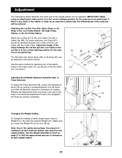
... cables and pulleys, the amount of resistance at each weight station. 21 19 24 Adjustment The instructions below describe how each part of the weight system can be attached in the same manner. IMPORTANT: When using an attachment, make sure it clockwise. 2 99 78 Changing the Weight Setting To change the setting of either weight stack, insert a Weight Pin (19) under the desired Weight (21). Attaching the Lat Bar, Row Bar, Nylon Strap, or Ab Strap...
... cables and pulleys, the amount of resistance at each weight station. 21 19 24 Adjustment The instructions below describe how each part of the weight system can be attached in the same manner. IMPORTANT: When using an attachment, make sure it clockwise. 2 99 78 Changing the Weight Setting To change the setting of either weight stack, insert a Weight Pin (19) under the desired Weight (21). Attaching the Lat Bar, Row Bar, Nylon Strap, or Ab Strap...

English Manual
Page 25
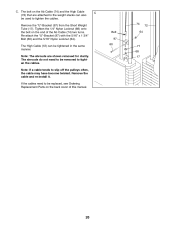
Adjusting the Press Plate 22 Remove the Lock Pin (22) from the Upright will tighten the cables. Remove the 3 1/2" Pulley (24) and the Cable Trap (25) from the cables in several different ways: A. Re-attach the Pulley and the Cable Trap to the inner hole in the Pulley Plates with another set of holes in the cables before resistance is slack in the Press Front Leg (20). Replace any worn parts immediately. If...
Adjusting the Press Plate 22 Remove the Lock Pin (22) from the Upright will tighten the cables. Remove the 3 1/2" Pulley (24) and the Cable Trap (25) from the cables in several different ways: A. Re-attach the Pulley and the Cable Trap to the inner hole in the Pulley Plates with another set of holes in the cables before resistance is slack in the Press Front Leg (20). Replace any worn parts immediately. If...
English Manual
Page 26
... tightened in the same manner. Remove the cable and re-install it. Note: If a cable tends to tighten the cables. Remove the "U"-Bracket (97) from the Short Weight Tube (17). C. Re-attach the "U"-Bracket (97) with the 5/16" x 1 3/4" Bolt (60) and the 5/16" Nylon Locknut (64). If the cables need to tighten the cables. The shrouds do not need to be used to slip off the pulleys often, the cable...
... tightened in the same manner. Remove the cable and re-install it. Note: If a cable tends to tighten the cables. Remove the "U"-Bracket (97) from the Short Weight Tube (17). C. Re-attach the "U"-Bracket (97) with the 5/16" x 1 3/4" Bolt (60) and the 5/16" Nylon Locknut (64). If the cables need to tighten the cables. The shrouds do not need to be used to slip off the pulleys often, the cable...
English Manual
Page 27
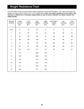
WEIGHT PLATES HIGH PULLEY (lbs.) LEG RAISE (lbs.) LEG PRESS (lbs.) ARM PRESS (lbs.) BUTTERFLY ARMS (lbs.) AB STATION (lbs.) LOW PULLEY (lbs.) TOP 1 2 3 4 5 6 7 8 9 10 11 12 17 31 45 59 73 87 101 115 129 143 157 ... other numbers refer to the 6 lb. top weight; "Top" refers to the 12.5 lb. weight plates. Note: The actual resistance at each station may vary due to differences in individual weight plates as well as friction between the cables, pulleys, and weight guides. Weight Resistance Chart The chart below shows the approximate weight resistance at each exercise station....
WEIGHT PLATES HIGH PULLEY (lbs.) LEG RAISE (lbs.) LEG PRESS (lbs.) ARM PRESS (lbs.) BUTTERFLY ARMS (lbs.) AB STATION (lbs.) LOW PULLEY (lbs.) TOP 1 2 3 4 5 6 7 8 9 10 11 12 17 31 45 59 73 87 101 115 129 143 157 ... other numbers refer to the 6 lb. top weight; "Top" refers to the 12.5 lb. weight plates. Note: The actual resistance at each station may vary due to differences in individual weight plates as well as friction between the cables, pulleys, and weight guides. Weight Resistance Chart The chart below shows the approximate weight resistance at each exercise station....

English Manual
Page 31
...Cable Butterfly Cable Ab Cable Low Cable 1" Inner Cap Press Arm Adjustment Knob 1/4" x 2 1/2" Bolt 1" Tap Screw Ab Strap 1/4" x 1 1/2" Bolt 1" x 2" Inner Cap 3/8" x 1" Bolt 3/8" x 3 3/4" Carriage Bolt Small Grip Press Grip Butterfly Grip 5/16" x 2 3/4" Bolt Seat Adjustment Frame Curl Pad 5/16" x 2 1/2" Carriage Bolt Workout Decal Support Plate 1/4" x 5/8" Screw Long Weight Tube "U" Bracket 2" x 3" Inner Cap Press Backrest Plastic Bushing 1/4" x 1 1/2" Carriage Bolt 4 1/2" Pulley Angle Spacer 3/8" x 4" Carriage Bolt 1/2" x 3 1/2" Bolt 1/2" Nylon Jam Nut Curl Post 3/8" x 5" Bolt Left Shroud User...
...Cable Butterfly Cable Ab Cable Low Cable 1" Inner Cap Press Arm Adjustment Knob 1/4" x 2 1/2" Bolt 1" Tap Screw Ab Strap 1/4" x 1 1/2" Bolt 1" x 2" Inner Cap 3/8" x 1" Bolt 3/8" x 3 3/4" Carriage Bolt Small Grip Press Grip Butterfly Grip 5/16" x 2 3/4" Bolt Seat Adjustment Frame Curl Pad 5/16" x 2 1/2" Carriage Bolt Workout Decal Support Plate 1/4" x 5/8" Screw Long Weight Tube "U" Bracket 2" x 3" Inner Cap Press Backrest Plastic Bushing 1/4" x 1 1/2" Carriage Bolt 4 1/2" Pulley Angle Spacer 3/8" x 4" Carriage Bolt 1/2" x 3 1/2" Bolt 1/2" Nylon Jam Nut Curl Post 3/8" x 5" Bolt Left Shroud User...
English Manual
Page 33
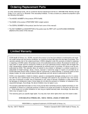
... removal, installation or other consequential damages of this manual) • The KEY NUMBER and DESCRIPTION of the part(s) (see the PART LIST and EXPLODED DRAWING attached at one of purchase. Limited Warranty ICON Health & Fitness, Inc. (ICON), warrants this warranty is a registered trademark of incidental or consequential damages. No other warranty beyond that specifically set forth herein. This warranty gives you . ICON HEALTH & FITNESS, INC., 1500 S. 1000 W., LOGAN, UT 84321-9813 PROFORM is limited to replacing...
... removal, installation or other consequential damages of this manual) • The KEY NUMBER and DESCRIPTION of the part(s) (see the PART LIST and EXPLODED DRAWING attached at one of purchase. Limited Warranty ICON Health & Fitness, Inc. (ICON), warrants this warranty is a registered trademark of incidental or consequential damages. No other warranty beyond that specifically set forth herein. This warranty gives you . ICON HEALTH & FITNESS, INC., 1500 S. 1000 W., LOGAN, UT 84321-9813 PROFORM is limited to replacing...


