
Uk Manual
Page 2
... a registered trademark of the warning decals. TABLE OF CONTENTS WARNING DECAL PLACEMENT 2 IMPORTANT PRECAUTIONS 3 BEFORE YOU BEGIN 5 ASSEMBLY 6 HOW TO USE THE CHEST PULSE SENSOR 15 OPERATION AND ADJUSTMENT 16 HOW TO FOLD AND MOVE THE TREADMILL 24 TROUBLESHOOTING 25 EXERCISE GUIDELINES 28 PART LIST 30 EXPLODED DRAWING 32 ORDERING REPLACEMENT PARTS Back Cover RECYCLING INFORMATION Back Cover WARNING DECAL PLACEMENT This drawing shows the locations of ICON IP, Inc. 2
... a registered trademark of the warning decals. TABLE OF CONTENTS WARNING DECAL PLACEMENT 2 IMPORTANT PRECAUTIONS 3 BEFORE YOU BEGIN 5 ASSEMBLY 6 HOW TO USE THE CHEST PULSE SENSOR 15 OPERATION AND ADJUSTMENT 16 HOW TO FOLD AND MOVE THE TREADMILL 24 TROUBLESHOOTING 25 EXERCISE GUIDELINES 28 PART LIST 30 EXPLODED DRAWING 32 ORDERING REPLACEMENT PARTS Back Cover RECYCLING INFORMATION Back Cover WARNING DECAL PLACEMENT This drawing shows the locations of ICON IP, Inc. 2
Uk Manual
Page 3
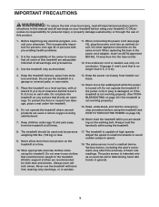
... the owner to avoid sudden jumps in the power cord adapter, insert an ASTA-approved BS1362, 13-amp fuse into an earthed circuit. When replacing the fuse in speed. 18. Place the treadmill on your treadmill before using your physician. Never move the walking belt while the power is not a medical device. Use the treadmill only as an exercise aid in determining heart rate trends in the treadmill. Do...
... the owner to avoid sudden jumps in the power cord adapter, insert an ASTA-approved BS1362, 13-amp fuse into an earthed circuit. When replacing the fuse in speed. 18. Place the treadmill on your treadmill before using your physician. Never move the walking belt while the power is not a medical device. Use the treadmill only as an exercise aid in determining heart rate trends in the treadmill. Do...
Uk Manual
Page 4
... in use this manual. Over exercising may result in this treadmill in -home use , before cleaning the treadmill, and before performing the mainte- Inspect and properly tighten all parts of the power switch.) 20. DANGER: 24. Never remove the motor hood un- SAVE THESE INSTRUCTIONS 4 Always remove the key, unplug the power cord, and press the power switch into any opening on page 5 for in a commercial, rental, or institutional setting. 26. nance and adjustment procedures...
... in use this manual. Over exercising may result in this treadmill in -home use , before cleaning the treadmill, and before performing the mainte- Inspect and properly tighten all parts of the power switch.) 20. DANGER: 24. Never remove the motor hood un- SAVE THESE INSTRUCTIONS 4 Always remove the key, unplug the power cord, and press the power switch into any opening on page 5 for in a commercial, rental, or institutional setting. 26. nance and adjustment procedures...

Uk Manual
Page 5
... front cover of this manual. The 900 ZLT treadmill offers an impressive selection of this manual. To help us . If you for selecting the revolutionary PROFORM® 900 ZLT treadmill. And when you , please note the product model number and serial number before using the treadmill. ing this manual, please see the front cover of features designed to make your benefit, read - Tray Handrail Upright Walking Belt Foot Rail Console Pulse Sensor Key/Clip Power Switch Idler Roller Adjustment Bolts...
... front cover of this manual. The 900 ZLT treadmill offers an impressive selection of this manual. To help us . If you for selecting the revolutionary PROFORM® 900 ZLT treadmill. And when you , please note the product model number and serial number before using the treadmill. ing this manual, please see the front cover of features designed to make your benefit, read - Tray Handrail Upright Walking Belt Foot Rail Console Pulse Sensor Key/Clip Power Switch Idler Roller Adjustment Bolts...
Uk Manual
Page 11
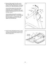
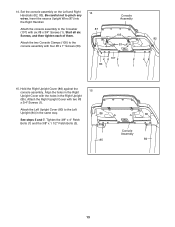
... the bracket on the Right Handrail (83). 10. Remove the two #8 x 3/4" Screws (1). Attach the Right Handrail (83) to avoid scratching the console assembly. Pull the Upright Wire out of the end of the Right Handrail. Do not tighten the Patch Bolts yet. 10 14 83 87 Bracket 38 4 13 86 85 11. Slide the Right Upright Cover (86) onto the Right...
... the bracket on the Right Handrail (83). 10. Remove the two #8 x 3/4" Screws (1). Attach the Right Handrail (83) to avoid scratching the console assembly. Pull the Upright Wire out of the end of the Right Handrail. Do not tighten the Patch Bolts yet. 10 14 83 87 Bracket 38 4 13 86 85 11. Slide the Right Upright Cover (86) onto the Right...
Uk Manual
Page 12
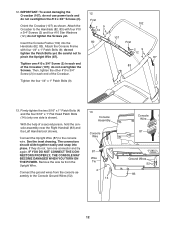
... the Console Ground Wires (52). 13 Console Assembly Console Wire 87 Wire Tie 4 14 Console Wire 87 Ground Wires 52 83 12 If they do not tighten the Patch Bolts yet. Remove the wire tie from the console assembly to the Handrails (82, 83) with four 1/4" x 1" Patch Bolts (9); IMPORTANT: To avoid damaging the Crossbar (107), do not use power tools and 12 do not overtighten the #10 x 3/4" Screws (2). Attach the Console Frame...
... the Console Ground Wires (52). 13 Console Assembly Console Wire 87 Wire Tie 4 14 Console Wire 87 Ground Wires 52 83 12 If they do not tighten the Patch Bolts yet. Remove the wire tie from the console assembly to the Handrails (82, 83) with four 1/4" x 1" Patch Bolts (9); IMPORTANT: To avoid damaging the Crossbar (107), do not use power tools and 12 do not overtighten the #10 x 3/4" Screws (2). Attach the Console Frame...
Uk Manual
Page 13
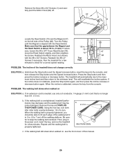
... Upright Wire (87) into the Right Handrail. See steps 5 and 7. Attach the Right Upright Cover with four #8 x 1" Screws (53). 14 87 Console Assembly 105 53 107 83 1 1 1 82 1 15. Attach the console assembly to the console assembly with two #8 x 3/4" Screws (1). Start all six Screws, and then tighten each of them. Attach the Left Upright Cover (80) to pinch any wires. 14. Set the console assembly on the Left and Right Handrails (82, 83). Tighten the 3/8" x 4" Patch Bolts...
... Upright Wire (87) into the Right Handrail. See steps 5 and 7. Attach the Right Upright Cover with four #8 x 1" Screws (53). 14 87 Console Assembly 105 53 107 83 1 1 1 82 1 15. Attach the console assembly to the console assembly with two #8 x 3/4" Screws (1). Start all six Screws, and then tighten each of them. Attach the Left Upright Cover (80) to pinch any wires. 14. Set the console assembly on the Left and Right Handrails (82, 83). Tighten the 3/8" x 4" Patch Bolts...
Uk Manual
Page 15
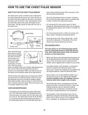
... chest strap and the sensor unit. Return the sensor unit to direct sunlight for extended periods of time; The chest pulse sensor is activated when the electrode areas are covered by shallow ridges). the chest pulse sensor shuts off when it is a problem, try the steps below 14° F (-10° C). Note: If the chest pulse sensor does not function when positioned as described, move it TROUBLESHOOTING The instructions on...
... chest strap and the sensor unit. Return the sensor unit to direct sunlight for extended periods of time; The chest pulse sensor is activated when the electrode areas are covered by shallow ridges). the chest pulse sensor shuts off when it is a problem, try the steps below 14° F (-10° C). Note: If the chest pulse sensor does not function when positioned as described, move it TROUBLESHOOTING The instructions on...
Uk Manual
Page 16
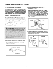
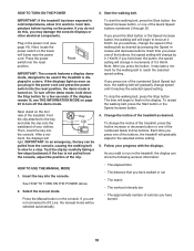
... installed by a qualified electrician. If you are plugging in the power cord in Australia, go to step 3. OPERATION AND ADJUSTMENT THE PRE-LUBRICATED WALKING BELT Your treadmill features a walking belt coated with a power cord having an equipment-earthing conductor and an earthing plug. HOW TO PLUG IN THE POWER CORD This product must be earthed. This product is tightened into an appropriate outlet that the screw is equipped with highperformance lubricant...
... installed by a qualified electrician. If you are plugging in the power cord in Australia, go to step 3. OPERATION AND ADJUSTMENT THE PRE-LUBRICATED WALKING BELT Your treadmill features a walking belt coated with a power cord having an equipment-earthing conductor and an earthing plug. HOW TO PLUG IN THE POWER CORD This product must be earthed. This product is tightened into an appropriate outlet that the screw is equipped with highperformance lubricant...
Uk Manual
Page 17
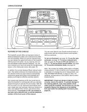
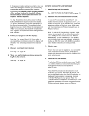
... turn on the power, see page 21. To use the treadmill, observe the alignment of measurement, see page 27). 17 In addition, the console features fifteen onboard workouts-five calorie workouts, five timed workouts, and five distance workouts. You can change the unit of the walking belt, and center the walking belt if necessary (see THE INFORMATION MODE on the front cover of a button. With the iFit Live mode, you use an iFit...
... turn on the power, see page 21. To use the treadmill, observe the alignment of measurement, see page 27). 17 In addition, the console features fifteen onboard workouts-five calorie workouts, five timed workouts, and five distance workouts. You can change the unit of the walking belt, and center the walking belt if necessary (see THE INFORMATION MODE on the front cover of a button. With the iFit Live mode, you use an iFit...
Uk Manual
Page 18
... power cord and press the power switch into the console. if you exercise, change the incline of the treadmill, press the Incline increase or decrease button or one of the buttons, the speed setting will change in the display. Insert the key into the reset position, the demo mode is turned on the console. ment, the displays will begin to cold temperatures, allow it reaches the selected speed setting. To change the speed of your progress with the displays. Start the walking belt...
... power cord and press the power switch into the console. if you exercise, change the incline of the treadmill, press the Incline increase or decrease button or one of the buttons, the speed setting will change in the display. Insert the key into the reset position, the demo mode is turned on the console. ment, the displays will begin to cold temperatures, allow it reaches the selected speed setting. To change the speed of your progress with the displays. Start the walking belt...
Uk Manual
Page 19
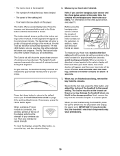
... speed of the treadmill 6. The My Trail tab will show a profile of the incline settings of the workout. Press the Home button to return to the default menu (see THE INFORMATION MODE on the chest pulse sensor, see step 6 on this , the treadmillʼs electrical components may damage the treadmill when you exercise, the white rectangle will appear, and then your heart rate accurately. As you exercise, the workout intensity level bar...
... speed of the treadmill 6. The My Trail tab will show a profile of the incline settings of the workout. Press the Home button to return to the default menu (see THE INFORMATION MODE on the chest pulse sensor, see step 6 on this , the treadmillʼs electrical components may damage the treadmill when you exercise, the white rectangle will appear, and then your heart rate accurately. As you exercise, the workout intensity level bar...
Uk Manual
Page 20
... not flash in the display instead of the treadmill during the workout. HOW TO USE AN ONBOARD WORKOUT 1. See HOW TO TURN ON THE POWER on the speed and in the display and the last segment ends. Press the Start button or the Speed increase button to a stop. Each workout is an estimate of the number of calories that you manually change the speed or incline of the workout duration. The flashing...
... not flash in the display instead of the treadmill during the workout. HOW TO USE AN ONBOARD WORKOUT 1. See HOW TO TURN ON THE POWER on the speed and in the display and the last segment ends. Press the Start button or the Speed increase button to a stop. Each workout is an estimate of the number of calories that you manually change the speed or incline of the workout duration. The flashing...
Uk Manual
Page 21
... instead of the iFit Live buttons. To resume the workout, press the Start button or the Speed increase button. Before a workout will download, you select a calorie workout or a timed workout, the display will begin to move at any time, go to download the next workout in the display. The walking belt will automatically adjust to a computer with SSID broadcast enabled (hidden networks are finished exercising, remove the key from the console. See step 6 on pages...
... instead of the iFit Live buttons. To resume the workout, press the Start button or the Speed increase button. Before a workout will download, you select a calorie workout or a timed workout, the display will begin to move at any time, go to download the next workout in the display. The walking belt will automatically adjust to a computer with SSID broadcast enabled (hidden networks are finished exercising, remove the key from the console. See step 6 on pages...
Uk Manual
Page 22
... you must connect your MP3 player, CD player, or other personal audio player to the speed and incline settings for the next segment. 6. To resume the workout, press the Start button or the Speed increase button. To use the MP3 jack, locate the included audio wire and plug it will show a track and the number of a personal trainer will count down to move at any time, press the Stop button. Start the workout. See step 3 on...
... you must connect your MP3 player, CD player, or other personal audio player to the speed and incline settings for the next segment. 6. To resume the workout, press the Start button or the Speed increase button. To use the MP3 jack, locate the included audio wire and plug it will show a track and the number of a personal trainer will count down to move at any time, press the Stop button. Start the workout. See step 3 on...

Uk Manual
Page 23
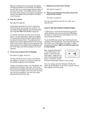
... send and receive workouts, workout logs, and updates, press the Enter button. To select the information mode, hold down the Stop button while inserting the key into the console or when you remove the key, the displays will remain lit, although the buttons will show the words NO IFIT MODULE. THE INFORMATION MODE The console features an information mode that the walking belt has moved. demo mode, press the Enter button or the Speed decrease button. To change the unit of...
... send and receive workouts, workout logs, and updates, press the Enter button. To select the information mode, hold down the Stop button while inserting the key into the console or when you remove the key, the displays will remain lit, although the buttons will show the words NO IFIT MODULE. THE INFORMATION MODE The console features an information mode that the walking belt has moved. demo mode, press the Enter button or the Speed decrease button. To change the unit of...
Uk Manual
Page 24
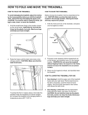
... TO FOLD THE TREADMILL To avoid damaging the treadmill, adjust the incline to the left; Then, remove the key and unplug the power cord. Moving the treadmill may require two people. 1. CAUTION: Do not hold the frame by the arrow below. Keep the treadmill out of the treadmill frame with both hands, and lower it back, do not pull on the handrail until the latch knob...
... TO FOLD THE TREADMILL To avoid damaging the treadmill, adjust the incline to the left; Then, remove the key and unplug the power cord. Moving the treadmill may require two people. 1. CAUTION: Do not hold the frame by the arrow below. Keep the treadmill out of the treadmill frame with both hands, and lower it back, do not pull on the handrail until the latch knob...
Uk Manual
Page 25
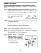
... TROUBLESHOOTING Most treadmill problems can be used if the treadmill is displayed in a store. If an extension cord is plugged in . c. If the power cord is needed , see the front cover of this manual. Remove the key from the console and UNPLUG a THE POWER CORD. If the treadmill still will not run, please see THE INFORMATION MODE on the treadmill frame near the power cord. PROBLEM: The console displays remain lit when you remove the key, the demo mode is turned on...
... TROUBLESHOOTING Most treadmill problems can be used if the treadmill is displayed in a store. If an extension cord is plugged in . c. If the power cord is needed , see the front cover of this manual. Remove the key from the console and UNPLUG a THE POWER CORD. If the treadmill still will not run, please see THE INFORMATION MODE on the treadmill frame near the power cord. PROBLEM: The console displays remain lit when you remove the key, the demo mode is turned on...
Uk Manual
Page 26
... button, insert the key into the console, and then release the Stop button and the Speed increase button. If the incline does not calibrate, press the Stop button again, and then press the Incline increase or decrease button again. PROBLEM: The walking belt slows when walked on , see the front cover of a turn. Then, plug in . Reattach the Motor Hood (not shown) 48 with the Reed Switch. The treadmill will recalibrate the incline system. If an extension cord is needed, use...
... button, insert the key into the console, and then release the Stop button and the Speed increase button. If the incline does not calibrate, press the Stop button again, and then press the Incline increase or decrease button again. PROBLEM: The walking belt slows when walked on , see the front cover of a turn. Then, plug in . Reattach the Motor Hood (not shown) 48 with the Reed Switch. The treadmill will recalibrate the incline system. If an extension cord is needed, use...
Uk Manual
Page 28
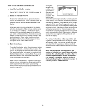
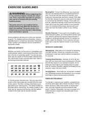
... a low intensity level for energy. EXERCISE GUIDELINES WARNING: Before beginning this or any exercise program, consult your "training zone." The pulse sensor is near the lowest number in general. The three numbers listed above your age define your physician. If your goal is to burn fat, adjust the intensity of exercise does your body begin to use your heart rate is to 10 minutes of...
... a low intensity level for energy. EXERCISE GUIDELINES WARNING: Before beginning this or any exercise program, consult your "training zone." The pulse sensor is near the lowest number in general. The three numbers listed above your age define your physician. If your goal is to burn fat, adjust the intensity of exercise does your body begin to use your heart rate is to 10 minutes of...

