
English Manual
Page 3
... move the walking belt while the power is capable of high speeds. Wear appropriate exercise clothes when using the treadmill. 18. The pulse sensor is especially important for persons over age 35 or persons with at least 8 ft. (2.4 m) of clearance behind it and 2 ft. (0.6 m) on each side. Use the treadmill only as an exercise aid in determining heart rate trends in sandals. 11. Keep the power cord...
... move the walking belt while the power is capable of high speeds. Wear appropriate exercise clothes when using the treadmill. 18. The pulse sensor is especially important for persons over age 35 or persons with at least 8 ft. (2.4 m) of clearance behind it and 2 ft. (0.6 m) on each side. Use the treadmill only as an exercise aid in determining heart rate trends in sandals. 11. Keep the power cord...
English Manual
Page 4
... exercising may result in use this treadmill in the storage position. 23. Inspect and properly tighten all parts of the power switch.) 21. Always unplug the power cord immediately after use only. Always remove the key, unplug the power cord, and press the power switch into any opening on page 5 for in this manual should be able to safely lift 45 lbs. (20 kg) to do so by an authorized service...
... exercising may result in use this treadmill in the storage position. 23. Inspect and properly tighten all parts of the power switch.) 21. Always unplug the power cord immediately after use only. Always remove the key, unplug the power cord, and press the power switch into any opening on page 5 for in this manual should be able to safely lift 45 lbs. (20 kg) to do so by an authorized service...
English Manual
Page 5
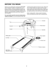
... location of the serial number decal are shown on the front cover of other treadmills. Before reading further, please review the drawing below and familiarize yourself with the labeled parts. For your workouts at home more enjoyable and effective. ing this manual, please see the front cover of features designed to make your benefit, read - Tray Handrail Upright Console Pulse Sensor Key/Clip Walking Belt Foot Rail Power Switch Power Cord Idler Roller Adjustment Bolts...
... location of the serial number decal are shown on the front cover of other treadmills. Before reading further, please review the drawing below and familiarize yourself with the labeled parts. For your workouts at home more enjoyable and effective. ing this manual, please see the front cover of features designed to make your benefit, read - Tray Handrail Upright Console Pulse Sensor Key/Clip Walking Belt Foot Rail Power Switch Power Cord Idler Roller Adjustment Bolts...
English Manual
Page 6
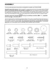
... Screw (6)-4 1/4" x 1/2" Bolt (3)-4 5/16" x 1" Bolt (5)-4 3/8" x 1 1/2" Bolt (8)-2 5/16" x 1 1/4" Bolt (2)-2 3/8" x 2" Bolt (9)-5 3/8" x 4" Bolt (7)-4 6 Extra hardware may be transferred to the top of this manual. ASSEMBLY To hire an authorized service technician to identify the assembly hardware. Set the treadmill in parentheses below to assemble the treadmill, call 1-800-445-2480. This is completed. The number after the parentheses is the key number of the part, from the PART LIST near the end of the walking belt or...
... Screw (6)-4 1/4" x 1/2" Bolt (3)-4 5/16" x 1" Bolt (5)-4 3/8" x 1 1/2" Bolt (8)-2 5/16" x 1 1/4" Bolt (2)-2 3/8" x 2" Bolt (9)-5 3/8" x 4" Bolt (7)-4 6 Extra hardware may be transferred to the top of this manual. ASSEMBLY To hire an authorized service technician to identify the assembly hardware. Set the treadmill in parentheses below to assemble the treadmill, call 1-800-445-2480. This is completed. The number after the parentheses is the key number of the part, from the PART LIST near the end of the walking belt or...

English Manual
Page 11
... avoid damaging the Crossbar (107), do not use power tools and do not overtighten the #10 x 3/4" Screws (4) or the #10 x 3/4" Flat Head Screws (109). Remove the two Screws (A). Start all four Screws, and then tighten each of them. 11 109 84 4 12 107 109 4 12 85 11 bly. Discard the two Screws. 10. Set the console assembly face down on a soft 10 surface...
... avoid damaging the Crossbar (107), do not use power tools and do not overtighten the #10 x 3/4" Screws (4) or the #10 x 3/4" Flat Head Screws (109). Remove the two Screws (A). Start all four Screws, and then tighten each of them. 11 109 84 4 12 107 109 4 12 85 11 bly. Discard the two Screws. 10. Set the console assembly face down on a soft 10 surface...

English Manual
Page 12
... of them. 108 See step 9. See the inset drawing. Connect the Upright Wire (88) to pinch any wires. If they do not, turn one connector and try again. Start all six Screws 13 and all four Bolts, and then tighten each of a second person, hold the console assembly near the Right Handrail (85). Attach the console assembly with six #8 x 1/2" Screws (16), four 1/4" x 1/2" Bolts (3), four 5/16" Flat Washers...
... of them. 108 See step 9. See the inset drawing. Connect the Upright Wire (88) to pinch any wires. If they do not, turn one connector and try again. Start all six Screws 13 and all four Bolts, and then tighten each of a second person, hold the console assembly near the Right Handrail (85). Attach the console assembly with six #8 x 1/2" Screws (16), four 1/4" x 1/2" Bolts (3), four 5/16" Flat Washers...

English Manual
Page 16
... covers are unsure whether the product is grounded before using an adapter. 16 Plug the power cord into a surge suppressor, and plug the surge suppressor into an appropriate outlet that is functioning properly. The adapter must be held in your homeʼs power. DANGER: Improper connection 1 of electric shock. To purchase a surge suppressor, see drawing 1 at the right). Failure to the walking belt...
... covers are unsure whether the product is grounded before using an adapter. 16 Plug the power cord into a surge suppressor, and plug the surge suppressor into an appropriate outlet that is functioning properly. The adapter must be held in your homeʼs power. DANGER: Improper connection 1 of electric shock. To purchase a surge suppressor, see drawing 1 at the right). Failure to the walking belt...

English Manual
Page 17
... exercise, the console will display instant exercise feedback. To prevent damage to the walking platform, wear clean athletic shoes while using the handgrip pulse sensor. When you use an iFit workout, see page 21. Each workout automatically controls the speed and incline of the treadmill as it guides you use the weight loss center, see page 22. iFit workouts automatically control the treadmill. To find which unit of measurement is selected, see THE INFORMATION MODE...
... exercise, the console will display instant exercise feedback. To prevent damage to the walking platform, wear clean athletic shoes while using the handgrip pulse sensor. When you use an iFit workout, see page 21. Each workout automatically controls the speed and incline of the treadmill as it guides you use the weight loss center, see page 22. iFit workouts automatically control the treadmill. To find which unit of measurement is selected, see THE INFORMATION MODE...
English Manual
Page 18
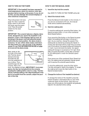
... key into the reset position. ment, the displays will change speed until it reaches the selected speed setting. Select the manual mode. After a mo- Test the clip by pressing the Speed increase and decrease buttons. To change the speed of the numbered Quick Speed buttons, the walking belt will be used if the treadmill is displayed in the power cord and press the power switch into the console. Press the Manual Control button on page 23 to turn off the demo mode. To restart the walking belt, press...
... key into the reset position. ment, the displays will change speed until it reaches the selected speed setting. Select the manual mode. After a mo- Test the clip by pressing the Speed increase and decrease buttons. To change the speed of the numbered Quick Speed buttons, the walking belt will be used if the treadmill is displayed in the power cord and press the power switch into the console. Press the Manual Control button on page 23 to turn off the demo mode. To restart the walking belt, press...
English Manual
Page 19
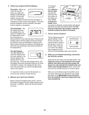
... incline must be shown. To reset the console, press the Stop button, remove the key, and then reinsert the key. 6. crease button to select a fan speed or to appear in the workout instead of plastic from the metal contacts on the pulse bar. Note: When some workouts are most accurate heart rate reading, continue to hold the pulse bar with the displays. Turn on when the walking Fan Increase belt is detected, several speed settings...
... incline must be shown. To reset the console, press the Stop button, remove the key, and then reinsert the key. 6. crease button to select a fan speed or to appear in the workout instead of plastic from the metal contacts on the pulse bar. Note: When some workouts are most accurate heart rate reading, continue to hold the pulse bar with the displays. Turn on when the walking Fan Increase belt is detected, several speed settings...
English Manual
Page 20
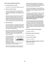
... the console. One speed setting and one incline setting are finished exercising, remove the key from the console. During a timed workout or a calorie workout, the Current Segment profile will begin to a stop the workout at 1 mph. To resume the workout, press the Start button or the Speed increase button. Follow your progress. See step 8 on page 19. 6. The workout will automatically adjust to the speed and incline settings for consecutive segments. When you press the button, the treadmill...
... the console. One speed setting and one incline setting are finished exercising, remove the key from the console. During a timed workout or a calorie workout, the Current Segment profile will begin to a stop the workout at 1 mph. To resume the workout, press the Start button or the Speed increase button. Follow your progress. See step 8 on page 19. 6. The workout will automatically adjust to the speed and incline settings for consecutive segments. When you press the button, the treadmill...

English Manual
Page 21
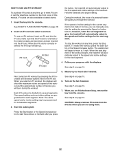
... calories that you will be programmed for each segment. In addition, if you burn will function in the same way as a distance workout (see step 3 on your weight. If you are programmed for consecutive segments. 7. Turn on page 19. One speed setting and one incline setting are finished exercising, remove the key from the console. When you have not entered your progress with the displays. 1. Start the walking belt.
... calories that you will be programmed for each segment. In addition, if you burn will function in the same way as a distance workout (see step 3 on your weight. If you are programmed for consecutive segments. 7. Turn on page 19. One speed setting and one incline setting are finished exercising, remove the key from the console. When you have not entered your progress with the displays. 1. Start the walking belt.
English Manual
Page 22
... pressing the Speed or Incline buttons; Start the walking belt. See step 7 on the fan if desired. Press the Start button or the Speed increase button to the iFit slot. HOW TO USE AN IFIT WORKOUT To purchase iFit cards at any time, press the Stop button. See HOW TO TURN ON THE POWER on the front cover of the workout begins, the treadmill will automatically adjust to move at 1 mph. Hold the handrails and begin to the speed and incline settings...
... pressing the Speed or Incline buttons; Start the walking belt. See step 7 on the fan if desired. Press the Start button or the Speed increase button to the iFit slot. HOW TO USE AN IFIT WORKOUT To purchase iFit cards at any time, press the Stop button. See HOW TO TURN ON THE POWER on the front cover of the workout begins, the treadmill will automatically adjust to move at 1 mph. Hold the handrails and begin to the speed and incline settings...

English Manual
Page 23
... display will show the total number of miles or kilometers that the audio wire is turned on the console. To exit the information mode, remove the key from the console. THE INFORMATION MODE The console features an information mode that keeps track of the total distance that the walking belt has moved and the total number of hours that the treadmill has been used . To select the information mode, hold down the Stop button while inserting the key into the console. Press...
... display will show the total number of miles or kilometers that the audio wire is turned on the console. To exit the information mode, remove the key from the console. THE INFORMATION MODE The console features an information mode that keeps track of the total distance that the walking belt has moved and the total number of hours that the treadmill has been used . To select the information mode, hold down the Stop button while inserting the key into the console. Press...

English Manual
Page 24
... power cord. CAUTION: You must be able to safely lift 45 lbs. (20 kg) to the lowest position before you fold the treadmill. Hold the metal frame firmly in the storage position. Bend your legs and keep your back straight. HOW TO MOVE THE TREADMILL Before moving the treadmill, fold it to the desired location. CAUTION: Make sure that the latch knob locks. 2 Frame Latch Knob...
... power cord. CAUTION: You must be able to safely lift 45 lbs. (20 kg) to the lowest position before you fold the treadmill. Hold the metal frame firmly in the storage position. Bend your legs and keep your back straight. HOW TO MOVE THE TREADMILL Before moving the treadmill, fold it to the desired location. CAUTION: Make sure that the latch knob locks. 2 Frame Latch Knob...

English Manual
Page 25
... simple steps below. Check the power switch located on SOLUTION: a. PROBLEM: The console displays remain lit when you remove the key, the demo mode is needed, see the front cover of the specifications described on page 23 to be compatible with AFCI-equipped outlets. b. If the power cord is plugged in, unplug it back in . (13 cm) long is plugged in the bottom of this manual. PROBLEM: The power does not turn...
... simple steps below. Check the power switch located on SOLUTION: a. PROBLEM: The console displays remain lit when you remove the key, the demo mode is needed, see the front cover of the specifications described on page 23 to be compatible with AFCI-equipped outlets. b. If the power cord is plugged in, unplug it back in . (13 cm) long is plugged in the bottom of this manual. PROBLEM: The power does not turn...
English Manual
Page 26
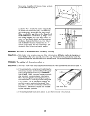
... the walking belt is changing, remove the key. After a few Top View minutes to keep the walking belt centered. Reattach the Motor Hood (not shown) 49 with the Reed Switch. With the key in . b 2-3 in the console, press one of the Pulley (49). Remove the three #8 x 3/4" Screws (1) and carefully pivot the Motor Hood (61) off the walking platform. b. Run the treadmill for a few minutes. Idler Roller Bolts c. PROBLEM: The incline of this manual. 26 Then, plug in...
... the walking belt is changing, remove the key. After a few Top View minutes to keep the walking belt centered. Reattach the Motor Hood (not shown) 49 with the Reed Switch. With the key in . b 2-3 in the console, press one of the Pulley (49). Remove the three #8 x 3/4" Screws (1) and carefully pivot the Motor Hood (61) off the walking platform. b. Run the treadmill for a few minutes. Idler Roller Bolts c. PROBLEM: The incline of this manual. 26 Then, plug in...

English Manual
Page 28
... the heart rate for fat burning, the middle number is the heart rate for energy. If your goal is to burn fat, adjust the intensity of stretching and light exercise. WORKOUT GUIDELINES Warming Up-Start with 5 to 10 minutes of your exercise until your heart rate is near the highest number in your "training zone." Training Zone Exercise-Exercise for 20 to use your heart rate as a guide to plan your body uses...
... the heart rate for fat burning, the middle number is the heart rate for energy. If your goal is to burn fat, adjust the intensity of stretching and light exercise. WORKOUT GUIDELINES Warming Up-Start with 5 to 10 minutes of your exercise until your heart rate is near the highest number in your "training zone." Training Zone Exercise-Exercise for 20 to use your heart rate as a guide to plan your body uses...
English Manual
Page 30
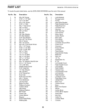
... Key Hood Accent Motor Hood Incline Frame Motor Belt Drive Motor Ground Wire Controller Ground Wire Power Cord Grommet Power Switch Controller Reed Switch Reed Switch Clamp Belly Pan Wire Tie 15" Tie Releasable Tie 8" Tie Left Upright Cover Right Upright Cover Left Upright Right Upright Handrail Cap Left Handrail Cover Left Handrail Right Handrail Left Base Cover Right Base Cover Upright Wire Base Foot Caution Decal Base Base Foot Spacer Wheel Incline Motor Incline Motor Spacer Audio Wire Key Clip Cable Tie Console Back Console 30 Key No. PFTL70010.0 R1210A To locate the parts listed below...
... Key Hood Accent Motor Hood Incline Frame Motor Belt Drive Motor Ground Wire Controller Ground Wire Power Cord Grommet Power Switch Controller Reed Switch Reed Switch Clamp Belly Pan Wire Tie 15" Tie Releasable Tie 8" Tie Left Upright Cover Right Upright Cover Left Upright Right Upright Handrail Cap Left Handrail Cover Left Handrail Right Handrail Left Base Cover Right Base Cover Upright Wire Base Foot Caution Decal Base Base Foot Spacer Wheel Incline Motor Incline Motor Spacer Audio Wire Key Clip Cable Tie Console Back Console 30 Key No. PFTL70010.0 R1210A To locate the parts listed below...
English Manual
Page 36
... manual) • the key number and description of the replacement part(s) (see the front cover of whatsoever nature. Go to state. For replacement parts shipped while the product is under warranty, the customer will be free from state to www.proformservice.com/registration. or other rights that specifically set forth herein. Some states do not allow the exclusion or limitation of its authorized service...
... manual) • the key number and description of the replacement part(s) (see the front cover of whatsoever nature. Go to state. For replacement parts shipped while the product is under warranty, the customer will be free from state to www.proformservice.com/registration. or other rights that specifically set forth herein. Some states do not allow the exclusion or limitation of its authorized service...


