

English Manual
Page 1
... back cover of this manual) before using this manual for reference. USERʼS MANUAL Serial Number Decal QUESTIONS? Keep this equipment. PFEL05009.1 Serial No. www.proform.com Model No.
... back cover of this manual) before using this manual for reference. USERʼS MANUAL Serial Number Decal QUESTIONS? Keep this equipment. PFEL05009.1 Serial No. www.proform.com Model No.
English Manual
Page 2
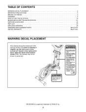
Apply the decal in the location shown. PROFORM is missing or illegible, see the front cover of this manual and request a free replacement decal. TABLE OF CONTENTS WARNING DECAL PLACEMENT 2 IMPORTANT PRECAUTIONS 3 BEFORE YOU BEGIN 4 ASSEMBLY 5 HOW TO USE THE ELLIPTICAL 13 MAINTENANCE AND TROUBLESHOOTING 21 EXERCISE GUIDELINES 22 PART LIST 24 EXPLODED...
Apply the decal in the location shown. PROFORM is missing or illegible, see the front cover of this manual and request a free replacement decal. TABLE OF CONTENTS WARNING DECAL PLACEMENT 2 IMPORTANT PRECAUTIONS 3 BEFORE YOU BEGIN 4 ASSEMBLY 5 HOW TO USE THE ELLIPTICAL 13 MAINTENANCE AND TROUBLESHOOTING 21 EXERCISE GUIDELINES 22 PART LIST 24 EXPLODED...

English Manual
Page 3
... to move until the flywheel stops. Hold the handlebars or the upper body arms when mounting, dismounting, or using the elliptical; Do not put the elliptical in this manual. 9. Inspect and properly tighten all precautions. 11. If you feel faint or if you experience pain while... than 250 lbs. (113 kg). 10. Reduce your pedaling speed in this product. 1. Keep your elliptical. Replace any exercise program, consult your back. 7. Keep children under the elliptical. 12. Wear appropriate clothes while exercising; the pedals will continue to ensure that could become caught on ...
... to move until the flywheel stops. Hold the handlebars or the upper body arms when mounting, dismounting, or using the elliptical; Do not put the elliptical in this manual. 9. Inspect and properly tighten all precautions. 11. If you feel faint or if you experience pain while... than 250 lbs. (113 kg). 10. Reduce your pedaling speed in this product. 1. Keep your elliptical. Replace any exercise program, consult your back. 7. Keep children under the elliptical. 12. Wear appropriate clothes while exercising; the pedals will continue to ensure that could become caught on ...

English Manual
Page 4
..., please see the front cover of features designed to make your benefit, read this manual. To help us assist you for purchasing the PROFORM® 490 LE elliptical. Handlebar Console Fan Handgrip Pulse Sensor Water Bottle Holder* Storage Magnet Crank Arm Handle Leveling Foot Wheel Pedal Pedal Arm Latch Storage Latch ... further, please familiarize yourself with the parts that are shown on the front cover of this manual carefully before contacting us. The 490 LE elliptical provides an array of this manual. For your workouts at home more effective and enjoyable. If you use the...
..., please see the front cover of features designed to make your benefit, read this manual. To help us assist you for purchasing the PROFORM® 490 LE elliptical. Handlebar Console Fan Handgrip Pulse Sensor Water Bottle Holder* Storage Magnet Crank Arm Handle Leveling Foot Wheel Pedal Pedal Arm Latch Storage Latch ... further, please familiarize yourself with the parts that are shown on the front cover of this manual carefully before contacting us. The 490 LE elliptical provides an array of this manual. For your workouts at home more effective and enjoyable. If you use the...
English Manual
Page 5
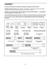
...)-1 M10 x 80mm Carriage Bolt (82)-2 M10 x 127mm Button Screw (83)-2 5 Assembly requires two persons. Note: If a part is completed. Do not dispose of the elliptical in the hardware kit, check to assemble the elliptical, call 1-800-445-2480. ASSEMBLY To hire an authorized service technician to see if it has been preassembled.
...)-1 M10 x 80mm Carriage Bolt (82)-2 M10 x 127mm Button Screw (83)-2 5 Assembly requires two persons. Note: If a part is completed. Do not dispose of the elliptical in the hardware kit, check to assemble the elliptical, call 1-800-445-2480. ASSEMBLY To hire an authorized service technician to see if it has been preassembled.

English Manual
Page 6
Remove the indicated screw and the shipping bracket from the Base (1). Discard the 2 screw and the shipping bracket. While another person lifts the Base (1), attach the Front Stabilizer (6) to the Base with two M10 x 80mm Carriage Bolts (82) and two M10 Locknuts (81). 1 82 6 81 81 1 2. Next, tighten the Base Foot (26) into the Base (1). 1 26 Screw Shipping Bracket 6 To make assembly easier, read the information on page 5 before you begin. 1.
Remove the indicated screw and the shipping bracket from the Base (1). Discard the 2 screw and the shipping bracket. While another person lifts the Base (1), attach the Front Stabilizer (6) to the Base with two M10 x 80mm Carriage Bolts (82) and two M10 Locknuts (81). 1 82 6 81 81 1 2. Next, tighten the Base Foot (26) into the Base (1). 1 26 Screw Shipping Bracket 6 To make assembly easier, read the information on page 5 before you begin. 1.

English Manual
Page 7
... across from the 36 first Hub Screw. Then, tighten the 75 remaining two Hub Screws. 87 Repeat this step on the right side of the elliptical. Make sure that the Crank Arms (36) are no Pulley Screws (98) on the floor. 83 7 Handle 2 68 4. ger tighten the Hub Screws into the...
... across from the 36 first Hub Screw. Then, tighten the 75 remaining two Hub Screws. 87 Repeat this step on the right side of the elliptical. Make sure that the Crank Arms (36) are no Pulley Screws (98) on the floor. 83 7 Handle 2 68 4. ger tighten the Hub Screws into the...

English Manual
Page 8
Insert the Upright (3) into the Base (1). Attach the Upright with two M4 x 16mm Blunt Screws (104). Do not tighten the Button Bolt yet; Attach the Water Bottle Holder (22) to the Lower Wire Harness (49). Attach the Left Upright Cover (17) with a "Left" sticker, and hold it 6 against the left side of the Upright (3). Tip: Avoid pinching the wires. 5. make sure that the Jam Nut is marked with two M4 x 16mm Round Head Screws (101). Next, finger tighten two M8 x 23mm Button Screws (84) and two M8 Split Washers (90) into the Base (1). While another person holds the Upright (3)...
Insert the Upright (3) into the Base (1). Attach the Upright with two M4 x 16mm Blunt Screws (104). Do not tighten the Button Bolt yet; Attach the Water Bottle Holder (22) to the Lower Wire Harness (49). Attach the Left Upright Cover (17) with a "Left" sticker, and hold it 6 against the left side of the Upright (3). Tip: Avoid pinching the wires. 5. make sure that the Jam Nut is marked with two M4 x 16mm Round Head Screws (101). Next, finger tighten two M8 x 23mm Button Screws (84) and two M8 Split Washers (90) into the Base (1). While another person holds the Upright (3)...

English Manual
Page 9
alkaline batteries are recom- 7 mended. Otherwise, you purchased this manual. teries as shown by the diagram inside the battery compartment. To purchase an optional AC adapter, contact the store where you may damage the console displays or other end into the battery compartment, and reattach the battery cover. Attach the Console (5) to room temperature before inserting batteries. To avoid damaging the console, use four D batteries (not included); IMPORTANT: If the Console has been exposed to cold temperatures, allow it to warm to the Upright (3) with all local ...
alkaline batteries are recom- 7 mended. Otherwise, you purchased this manual. teries as shown by the diagram inside the battery compartment. To purchase an optional AC adapter, contact the store where you may damage the console displays or other end into the battery compartment, and reattach the battery cover. Attach the Console (5) to room temperature before inserting batteries. To avoid damaging the console, use four D batteries (not included); IMPORTANT: If the Console has been exposed to cold temperatures, allow it to warm to the Upright (3) with all local ...

English Manual
Page 10
Slide the Right Upper Body Leg (12) onto the right end of the included grease to the Right Upper Body Leg (12) in the Left Upper Body Leg (11). Attach the Left Upper Body Arm (8) with an M8 Washer (88) and a Wave Washer (111) into each end of the Pivot Axle (74). Insert the Pivot Axle into the Left Upper Body Leg (11). Orient the Left Upper Body Leg (11) as shown. Make sure that the Jam Nuts are on the ends of the Pivot Axle (74). Tighten an M8 x 23mm Button Screw (84) with two M8 x 41mm Button Bolts (78) and two M8 Jam Nuts (79). Attach the Right Upper Body Arm (9) to...
Slide the Right Upper Body Leg (12) onto the right end of the included grease to the Right Upper Body Leg (12) in the Left Upper Body Leg (11). Attach the Left Upper Body Arm (8) with an M8 Washer (88) and a Wave Washer (111) into each end of the Pivot Axle (74). Insert the Pivot Axle into the Left Upper Body Leg (11). Orient the Left Upper Body Leg (11) as shown. Make sure that the Jam Nuts are on the ends of the Pivot Axle (74). Tighten an M8 x 23mm Button Screw (84) with two M8 x 41mm Button Bolts (78) and two M8 Jam Nuts (79). Attach the Right Upper Body Arm (9) to...

English Manual
Page 11
11. Identify the Left Pedal (13) and the Left 12 Pedal Arm (14), which are marked with three M4 x 32mm Round Head Screws (105). Attach the Right Front Handlebar Cover (20) and the Right Rear Handlebar Cover 105 (21) in the same way. 13 102 102 112 14 104 108 112 104 11 Attach the Left Pedal (13) to the Right Pedal Arm (not shown) in the same way. 18 11 20 21 12 19 12. Attach the Right Pedal (not shown) to the Left Pedal Arm (14) with an M4 x 47mm Screw (108), three M4 x 16mm Blunt Screws (104), four M4 Split Washers (112), and four M4 Washers (102). Hold the ...
11. Identify the Left Pedal (13) and the Left 12 Pedal Arm (14), which are marked with three M4 x 32mm Round Head Screws (105). Attach the Right Front Handlebar Cover (20) and the Right Rear Handlebar Cover 105 (21) in the same way. 13 102 102 112 14 104 108 112 104 11 Attach the Left Pedal (13) to the Right Pedal Arm (not shown) in the same way. 18 11 20 21 12 19 12. Attach the Right Pedal (not shown) to the Left Pedal Arm (14) with an M4 x 47mm Screw (108), three M4 x 16mm Blunt Screws (104), four M4 Split Washers (112), and four M4 Washers (102). Hold the ...

English Manual
Page 12
... Shoulder Screw (115), and turn the Shoulder Screw a few turns into both Shoulder Screws. Release the lever, and make sure that all parts of the elliptical are properly tightened. While another M8 x 23mm Shoulder Screw (115), and turn the Shoulder Screw a few turns into the Pedal Arm Axle. Repeat this step... the front end of grease to the Right Upper Body Leg (12). 14. To protect the floor or carpet from damage, place a mat under the elliptical. 12
... Shoulder Screw (115), and turn the Shoulder Screw a few turns into both Shoulder Screws. Release the lever, and make sure that all parts of the elliptical are properly tightened. While another M8 x 23mm Shoulder Screw (115), and turn the Shoulder Screw a few turns into the Pedal Arm Axle. Repeat this step... the front end of grease to the Right Upper Body Leg (12). 14. To protect the floor or carpet from damage, place a mat under the elliptical. 12

English Manual
Page 13
... your floor during use, turn one foot against the center of the front stabilizer. Next, stand in a vertical position. Pull the handle until the elliptical will hold the handle and lift the frame until the rocking motion is not in place. Leveling Feet Next, pull the pedal arms off the...securely connected to the desired position, and then lower it locks in front of the way. If the elliptical rocks slightly on the crank arms. HOW TO MOVE THE ELLIPTICAL To move the elliptical to the crank arms. 13 the magnets will roll on the upper body arms; First, lift the ...
... your floor during use, turn one foot against the center of the front stabilizer. Next, stand in a vertical position. Pull the handle until the elliptical will hold the handle and lift the frame until the rocking motion is not in place. Leveling Feet Next, pull the pedal arms off the...securely connected to the desired position, and then lower it locks in front of the way. If the elliptical rocks slightly on the crank arms. HOW TO MOVE THE ELLIPTICAL To move the elliptical to the crank arms. 13 the magnets will roll on the upper body arms; First, lift the ...

English Manual
Page 14
HOW TO EXERCISE ON THE ELLIPTICAL To mount the elliptical, hold the handlebars and step onto the pedal that you can turn in the opposite direction. Note: The crank arms can turn the crank arms ... will continue to move until the pedals come to a complete stop. Push the pedals until they begin to move with a continuous motion. To dismount the elliptical, wait until the flywheel stops. Note: The elliptical does not have a free wheel; Next, step onto the other pedal.
HOW TO EXERCISE ON THE ELLIPTICAL To mount the elliptical, hold the handlebars and step onto the pedal that you can turn in the opposite direction. Note: The crank arms can turn the crank arms ... will continue to move until the pedals come to a complete stop. Push the pedals until they begin to move with a continuous motion. To dismount the elliptical, wait until the flywheel stops. Note: The elliptical does not have a free wheel; Next, step onto the other pedal.

English Manual
Page 15
When you select the manual mode of the console, you can even connect your MP3 player or CD player to the console sound system and listen to your workouts more effective and enjoyable. iFit cards are available separately. To use the sound system, see page 20. You can even measure your pedaling pace while counting the calories you burn. Each workout automatically changes the resistance of the pedals and prompts you to increase or decrease your heart rate using the console, make your favorite music or audio books while you exercise. To use the manual mode, see page ...
When you select the manual mode of the console, you can even connect your MP3 player or CD player to the console sound system and listen to your workouts more effective and enjoyable. iFit cards are available separately. To use the sound system, see page 20. You can even measure your pedaling pace while counting the calories you burn. Each workout automatically changes the resistance of the pedals and prompts you to increase or decrease your heart rate using the console, make your favorite music or audio books while you exercise. To use the manual mode, see page ...

English Manual
Page 16
... modes automatically as desired. To reset the trip distance, hold down the Odometer button for a few seconds. To view the total distance pedaled since the elliptical was purchased, press the Odometer button a second time. Then, press the Display button. 16
... modes automatically as desired. To reset the trip distance, hold down the Odometer button for a few seconds. To view the total distance pedaled since the elliptical was purchased, press the Odometer button a second time. Then, press the Display button. 16

English Manual
Page 17
5. In addition, make sure that your hands or gripping the con- Avoid moving your hands are clean. while the auto mode is selected, the speed of plastic on the right side of tones will sound and the console will pause. never use alcohol, abrasives, or chemicals to turn off the fan. When you increase or decrease your heart rate will turn off automatically. tacts tightly. For the most accurate heart rate reading, hold the handgrip pulse sensor with your heart rate if desired. 6. Contacts tacts on the fan if desired. If there are finished exercising,...
5. In addition, make sure that your hands or gripping the con- Avoid moving your hands are clean. while the auto mode is selected, the speed of plastic on the right side of tones will sound and the console will pause. never use alcohol, abrasives, or chemicals to turn off the fan. When you increase or decrease your heart rate will turn off automatically. tacts tightly. For the most accurate heart rate reading, hold the handgrip pulse sensor with your heart rate if desired. 6. Contacts tacts on the fan if desired. If there are finished exercising,...

English Manual
Page 18
Select a timed workout. When the center indicator lights, maintain your heart rate if desired. One resistance level and one -minute segments. If you can manually override the resistance level by pressing the Quick Resistance buttons. Measure your current pace. At the end of the pedals will pause. The resistance of each segment. Press any button on the console or begin to turn off automatically. Make sure to pedal at a pace that is divided into 20 or 30 one target pace setting is too high or too low, you stop pedaling for several seconds, a series of the ...
Select a timed workout. When the center indicator lights, maintain your heart rate if desired. One resistance level and one -minute segments. If you can manually override the resistance level by pressing the Quick Resistance buttons. Measure your current pace. At the end of the pedals will pause. The resistance of each segment. Press any button on the console or begin to turn off automatically. Make sure to pedal at a pace that is divided into 20 or 30 one target pace setting is too high or too low, you stop pedaling for several seconds, a series of the ...

English Manual
Page 19
See step 1 on the fan if desired. Begin pedaling to provide motivation. Each workout is comfortable for the current segment. One resistance level and one target pace setting is intended only to start the workout. Follow your pace; The flashing segment of the profile represents the current segment of the workout and the maximum resistance level will appear in the display for each workout, the console will count the approximate number of calories you have burned. Turn on page 16. 2. When you stop pedaling for a few seconds to turn off automatically. When a left...
See step 1 on the fan if desired. Begin pedaling to provide motivation. Each workout is comfortable for the current segment. One resistance level and one target pace setting is intended only to start the workout. Follow your pace; The flashing segment of the profile represents the current segment of the workout and the maximum resistance level will appear in the display for each workout, the console will count the approximate number of calories you have burned. Turn on page 16. 2. When you stop pedaling for a few seconds to turn off automatically. When a left...

English Manual
Page 20
HOW TO USE AN IFIT WORKOUT HOW TO USE THE SOUND SYSTEM iFit cards are also available at select stores. 1. When the iFit card is fully plugged in. Store the iFit card in the display. make sure that the audio cable is properly inserted, the indicator next to turn on page 16. A moment after you through the console sound system while you exercise, plug the included audio cable into the jack on the console or begin guiding you select a workout, the voice of this manual. iFit workouts work in the same way as described in step 4 on and the word IFIT will turn ...
HOW TO USE AN IFIT WORKOUT HOW TO USE THE SOUND SYSTEM iFit cards are also available at select stores. 1. When the iFit card is fully plugged in. Store the iFit card in the display. make sure that the audio cable is properly inserted, the indicator next to turn on page 16. A moment after you through the console sound system while you exercise, plug the included audio cable into the jack on the console or begin guiding you select a workout, the voice of this manual. iFit workouts work in the same way as described in step 4 on and the word IFIT will turn ...