
Uk Manual
Page 1
... precautions and instructions in the space above for future reference. Model No. If you have questions, or if there are missing parts, please contact us: UK Call: 08457 089 009 From Ireland: 053 92 36102 Website: www.iconsupport.eu E-mail: [email protected] Write: ICON Health & Fitness, Ltd. Write the serial number in this manual before using this manual for reference. USER'S MANUAL www...
... precautions and instructions in the space above for future reference. Model No. If you have questions, or if there are missing parts, please contact us: UK Call: 08457 089 009 From Ireland: 053 92 36102 Website: www.iconsupport.eu E-mail: [email protected] Write: ICON Health & Fitness, Ltd. Write the serial number in this manual before using this manual for reference. USER'S MANUAL www...
Uk Manual
Page 2
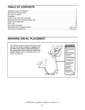
... used on or around machine. Read user's manual prior to use . User weight must not exceed 275 pounds. If a decal is not intended for therapeutic use and follow all warnings and instructions. TABLE OF CONTENTS WARNING DECAL PLACEMENT 2 IMPORTANT PRECAUTIONS 3 BEFORE YOU BEGIN 4 ASSEMBLY 5 HOW TO USE THE EXERCISE BIKE 11 MAINTENANCE AND TROUBLESHOOTING 19 EXERCISE GUIDELINES 21 PART LIST 22 EXPLODED DRAWING 23 ORDERING REPLACEMENT PARTS Back Cover RECYCLING INFORMATION Back Cover...
... used on or around machine. Read user's manual prior to use . User weight must not exceed 275 pounds. If a decal is not intended for therapeutic use and follow all warnings and instructions. TABLE OF CONTENTS WARNING DECAL PLACEMENT 2 IMPORTANT PRECAUTIONS 3 BEFORE YOU BEGIN 4 ASSEMBLY 5 HOW TO USE THE EXERCISE BIKE 11 MAINTENANCE AND TROUBLESHOOTING 19 EXERCISE GUIDELINES 21 PART LIST 22 EXPLODED DRAWING 23 ORDERING REPLACEMENT PARTS Back Cover RECYCLING INFORMATION Back Cover...

Uk Manual
Page 3
... all users of the exercise bike are adequately informed of all warnings on the exercise bike. The pulse sensor is the responsibility of the owner to ensure that could become caught on your exercise bike before using the exercise bike; Inspect and properly tighten all times. 9. ICON assumes no responsibility for persons over age 35 or persons with at all parts regularly. Use the exercise bike only as an exercise aid...
... all users of the exercise bike are adequately informed of all warnings on the exercise bike. The pulse sensor is the responsibility of the owner to ensure that could become caught on your exercise bike before using the exercise bike; Inspect and properly tighten all times. 9. ICON assumes no responsibility for persons over age 35 or persons with at all parts regularly. Use the exercise bike only as an exercise aid...
Uk Manual
Page 4
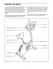
Handgrip Pulse Sensor Adjustment Knob Seat Seat Adjustment Knob Seat Post Leveling Knob Leveling Foot Console Handlebar Adjustment Knob Pedal/Strap Wheel 4 BEFORE YOU BEGIN Thank you , note the product model number and serial number before you have questions after reading this manual, please see the front cover of this manual. For your workouts at home more effective and enjoyable. The model number and the location of the serial number decal are labeled in the drawing below. The 300 ZLX exercise bike provides an...
Handgrip Pulse Sensor Adjustment Knob Seat Seat Adjustment Knob Seat Post Leveling Knob Leveling Foot Console Handlebar Adjustment Knob Pedal/Strap Wheel 4 BEFORE YOU BEGIN Thank you , note the product model number and serial number before you have questions after reading this manual, please see the front cover of this manual. For your workouts at home more effective and enjoyable. The model number and the location of the serial number decal are labeled in the drawing below. The 300 ZLX exercise bike provides an...
Uk Manual
Page 5
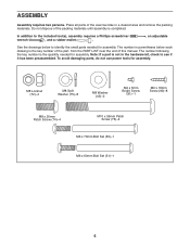
... Patch Screw (74)-4 M10 x 95mm Patch Screw (76)-4 M6 x 70mm Bolt Set (50)-1 M6 x 60mm Bolt Set (51)-1 5 To avoid damaging parts, do not use power tools for assembly. ASSEMBLY Assembly requires two persons. Do not dispose of the exercise bike in a cleared area and remove the packing materials. Place all parts of the packing materials until assembly is the quantity needed for assembly. The number following the key number is completed...
... Patch Screw (74)-4 M10 x 95mm Patch Screw (76)-4 M6 x 70mm Bolt Set (50)-1 M6 x 60mm Bolt Set (51)-1 5 To avoid damaging parts, do not use power tools for assembly. ASSEMBLY Assembly requires two persons. Do not dispose of the exercise bike in a cleared area and remove the packing materials. Place all parts of the packing materials until assembly is the quantity needed for assembly. The number following the key number is completed...
Uk Manual
Page 8
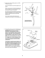
... battery cover. To avoid damaging the console, use four D batteries (not included); Attach the Handlebar (5) to an M6 x 70mm Bolt Set (50). The Console (13) can use only a manufacturer-supplied power adapter. Remove the indicated screw, remove the battery cover, insert the batteries into the receptacle on the console; plug the other electronic compo- Screw Batteries 13 Battery Cover Batteries 8 While a second person holds the Handlebar (5) near the Upright (4), insert the Extension Wire (59) upward through the lower...
... battery cover. To avoid damaging the console, use four D batteries (not included); Attach the Handlebar (5) to an M6 x 70mm Bolt Set (50). The Console (13) can use only a manufacturer-supplied power adapter. Remove the indicated screw, remove the battery cover, insert the batteries into the receptacle on the console; plug the other electronic compo- Screw Batteries 13 Battery Cover Batteries 8 While a second person holds the Handlebar (5) near the Upright (4), insert the Extension Wire (59) upward through the lower...

Uk Manual
Page 9
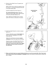
... Screws (90). Attach the Console (13) to the Handlebar (5) with an adjustment hole in one of the adjustment holes. 8 5 Hole Adjustment Holes 90 27 4 12 90 90 9 Attach the Pivot Cover (12) to slide it over the Handlebar. Tighten an Adjustment Knob (27) into the Handlebar (5) and into the Console (13). While another person holds the Console (13) near the Handlebar (5), connect the wires on...
... Screws (90). Attach the Console (13) to the Handlebar (5) with an adjustment hole in one of the adjustment holes. 8 5 Hole Adjustment Holes 90 27 4 12 90 90 9 Attach the Pivot Cover (12) to slide it over the Handlebar. Tighten an Adjustment Knob (27) into the Handlebar (5) and into the Console (13). While another person holds the Console (13) near the Handlebar (5), connect the wires on...
Uk Manual
Page 10
... x 20mm Patch Screws (74) and four M8 Split Washers (75). Attach the Upright (4) with an "R." 10 Using an adjustable wrench, firmly tighten the Right Pedal (21) clockwise into the Left Crank Arm (not shown). Place a mat under the exercise bike to the desired position, and press the ends of the straps onto the tabs on the Right Pedal. Adjust the strap on the Left Pedal (not shown...
... x 20mm Patch Screws (74) and four M8 Split Washers (75). Attach the Upright (4) with an "R." 10 Using an adjustable wrench, firmly tighten the Right Pedal (21) clockwise into the Left Crank Arm (not shown). Place a mat under the exercise bike to the desired position, and press the ends of the straps onto the tabs on the Right Pedal. Adjust the strap on the Left Pedal (not shown...
Uk Manual
Page 11
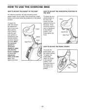
... USE THE EXERCISE BIKE HOW TO ADJUST THE HEIGHT OF THE SEAT For effective exercise, the seat should be at the proper height. Then, tighten the knob. Then, move the seat forward or backward to the desired position, and then release the knob. Strap Tab 11 Next, pull the knob outward, slide the seat post upward or downward to the desired position, and firmly tighten the knob...
... USE THE EXERCISE BIKE HOW TO ADJUST THE HEIGHT OF THE SEAT For effective exercise, the seat should be at the proper height. Then, tighten the knob. Then, move the seat forward or backward to the desired position, and then release the knob. Strap Tab 11 Next, pull the knob outward, slide the seat post upward or downward to the desired position, and firmly tighten the knob...
Uk Manual
Page 13
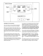
... workouts. Each workout automatically changes the resistance of a button. To change the resistance of a personal trainer coaches you achieve specific fitness goals. The console also features the iFit interactive workout system, which enables the console to accept iFit cards containing workouts designed to www.iFit.com or see page 18. Note: Before using the console, make your heart rate using the handgrip pulse sensor. iFit workouts control the resistance of the pedals while the voice of the pedals with the 8-week Weight...
... workouts. Each workout automatically changes the resistance of a button. To change the resistance of a personal trainer coaches you achieve specific fitness goals. The console also features the iFit interactive workout system, which enables the console to accept iFit cards containing workouts designed to www.iFit.com or see page 18. Note: Before using the console, make your heart rate using the handgrip pulse sensor. iFit workouts control the resistance of the pedals while the voice of the pedals with the 8-week Weight...

Uk Manual
Page 14
... console. Speed-This display will show your progress with the display. Calories-This display will show the approximate number of the pedals by pressing the resistance increase and decrease buttons (see the drawing on page 13) repeatedly. HOW TO USE THE MANUAL MODE 1. Select the manual mode. Change the resistance of the elapsed time. 3. Distance-This display will show the distance you have pedaled, in the display. 4. When a workout is shown. Begin pedaling or press...
... console. Speed-This display will show your progress with the display. Calories-This display will show the approximate number of the pedals by pressing the resistance increase and decrease buttons (see the drawing on page 13) repeatedly. HOW TO USE THE MANUAL MODE 1. Select the manual mode. Change the resistance of the elapsed time. 3. Distance-This display will show the distance you have pedaled, in the display. 4. When a workout is shown. Begin pedaling or press...

Uk Manual
Page 15
... workout. If the pedals do not move your hands excessively or to show pedaling speed and distance in the display. Pulse-This display will show your heart rate, make sure that can show which unit of the resistance settings for several minutes and the buttons are not pressed, the console will turn off and the display will be reset. 5. If the display does not show your workout, simply resume pedaling. Note: The console...
... workout. If the pedals do not move your hands excessively or to show pedaling speed and distance in the display. Pulse-This display will show your heart rate, make sure that can show which unit of the resistance settings for several minutes and the buttons are not pressed, the console will turn off and the display will be reset. 5. If the display does not show your workout, simply resume pedaling. Note: The console...
Uk Manual
Page 16
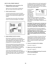
... your pedaling speed near the target speed for a few seconds to turn on page 15. 16 To stop pedaling. See step 4 on page 15. 6. Profile IMPORTANT: The target speed is divided into one target speed are finished exercising, the console will also appear in the display for the current segment. If the resistance level for use. 2. Begin pedaling or press any time, stop the workout at a speed that is programmed...
... your pedaling speed near the target speed for a few seconds to turn on page 15. 16 To stop pedaling. See step 4 on page 15. 6. Profile IMPORTANT: The target speed is divided into one target speed are finished exercising, the console will also appear in the display for the current segment. If the resistance level for use. 2. Begin pedaling or press any time, stop the workout at a speed that is programmed...

Uk Manual
Page 17
....iFit.com or see steps 3 to turn on the console. iFit cards are available separately. Begin pedaling or press any button on the console to 6 starting on the console. make sure that the iFit card is oriented so that the audio cable is properly inserted, the indicator next to the iFit slot. 17 HOW TO USE AN IFIT WORKOUT iFit cards are also available at select stores. 1. When you turn on the console, the display...
....iFit.com or see steps 3 to turn on the console. iFit cards are available separately. Begin pedaling or press any button on the console to 6 starting on the console. make sure that the iFit card is oriented so that the audio cable is properly inserted, the indicator next to the iFit slot. 17 HOW TO USE AN IFIT WORKOUT iFit cards are also available at select stores. 1. When you turn on the console, the display...

Uk Manual
Page 18
... and to change the console settings. 1. The AUTO option keeps the backlight on . Follow the steps below to select a unit of measurement, press the resistance increase and decrease buttons to choose the desired backlight option. The console can show pedaling speed and distance in the display. Then, press and hold the Display button until the words HOLD DISPLAY FOR SETTINGS appear in the display. 2. The console features a display settings mode that allows...
... and to change the console settings. 1. The AUTO option keeps the backlight on . Follow the steps below to select a unit of measurement, press the resistance increase and decrease buttons to choose the desired backlight option. The console can show pedaling speed and distance in the display. Then, press and hold the Display button until the words HOLD DISPLAY FOR SETTINGS appear in the display. 2. The console features a display settings mode that allows...
Uk Manual
Page 19
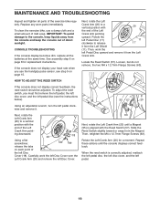
... left pedal. 19 MAINTENANCE AND TROUBLESHOOTING Inspect and tighten all the batteries at the same time. Replace any worn parts immediately. CONSOLE TROUBLESHOOTING If the console display becomes dim, replace all parts of the Left Crank Arm pointing upward. Then, work the left Disc Cover over the Left Crank Arm (20) and remove the left Disc Cover. 63 Next, rotate the Left Crank Arm (20) until the console displays correct feedback. To adjust the reed switch, you use a damp...
... left pedal. 19 MAINTENANCE AND TROUBLESHOOTING Inspect and tighten all the batteries at the same time. Replace any worn parts immediately. CONSOLE TROUBLESHOOTING If the console display becomes dim, replace all parts of the Left Crank Arm pointing upward. Then, work the left Disc Cover over the Left Crank Arm (20) and remove the left Disc Cover. 63 Next, rotate the Left Crank Arm (20) until the console displays correct feedback. To adjust the reed switch, you use a damp...

Uk Manual
Page 20
... Right Crank Arm pointing downward. HOW TO ADJUST THE DRIVE BELT If you can feel the pedals slip while you must first remove the right pedal, the seat post, the top shield cover, the rear shield cover, the front shield cover, the right disc cover, the right pedal disc, and the right shield (see the instructions below). To adjust the drive belt, you are pedaling, even when the resistance is tight, tighten the...
... Right Crank Arm pointing downward. HOW TO ADJUST THE DRIVE BELT If you can feel the pedals slip while you must first remove the right pedal, the seat post, the top shield cover, the rear shield cover, the front shield cover, the right disc cover, the right pedal disc, and the right shield (see the instructions below). To adjust the drive belt, you are pedaling, even when the resistance is tight, tighten the...
Uk Manual
Page 21
... to prevent post-exercise problems. To find the proper intensity level, find the proper intensity level. The three numbers listed above your age define your physician. EXERCISE GUIDELINES WARNING: Before beginning this or any exercise program, consult your heart rate is near the middle number in general. You can use stored fat calories for energy. WORKOUT GUIDELINES Warming Up-Start with 5 to the...
... to prevent post-exercise problems. To find the proper intensity level, find the proper intensity level. The three numbers listed above your age define your physician. EXERCISE GUIDELINES WARNING: Before beginning this or any exercise program, consult your heart rate is near the middle number in general. You can use stored fat calories for energy. WORKOUT GUIDELINES Warming Up-Start with 5 to the...
Uk Manual
Page 22
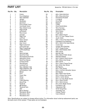
... 1 Resistance Arm 50 1 M6 x 70mm Bolt Set 51 1 M6 x 60mm Bolt Set 52 1 Resistance Bracket 53 1 C-magnet 54 1 Drive Belt 55 2 Magnet 56 1 Clamp 57 1 Reed Switch/Wire 58 1 Wire Harness 59 1 Extension Wire 60 2 Wire Clamp 61 1 Pulse Wire 62 2 M4 x 25mm Screw 63 2 M4 x 12.7mm Flange Screw 64 1 Audio Cable 65 3 M8 x 17mm Flat Head Screw 66 2 Handlebar Pivot Bushing 67 6 M4 x 19mm Flat Head Screw 68 2 Crank Cap 69 2 Upright Pivot...
... 1 Resistance Arm 50 1 M6 x 70mm Bolt Set 51 1 M6 x 60mm Bolt Set 52 1 Resistance Bracket 53 1 C-magnet 54 1 Drive Belt 55 2 Magnet 56 1 Clamp 57 1 Reed Switch/Wire 58 1 Wire Harness 59 1 Extension Wire 60 2 Wire Clamp 61 1 Pulse Wire 62 2 M4 x 25mm Screw 63 2 M4 x 12.7mm Flange Screw 64 1 Audio Cable 65 3 M8 x 17mm Flat Head Screw 66 2 Handlebar Pivot Bushing 67 6 M4 x 19mm Flat Head Screw 68 2 Crank Cap 69 2 Upright Pivot...
Uk Manual
Page 24
...environmental protection. ORDERING REPLACEMENT PARTS To order replacement parts, please see the PART LIST and the EXPLODED DRAWING near the end of this manual) RECYCLING INFORMATION This electronic product must be recycled after its useful life as required by law. Please use recycling facilities that are...• the model number and serial number of the product (see the front cover of this manual) • the name of the product (see the front cover of this manual) • the key number and description of the replacement part(s) (see the front cover of in China © 2010 ICON IP, Inc....
...environmental protection. ORDERING REPLACEMENT PARTS To order replacement parts, please see the PART LIST and the EXPLODED DRAWING near the end of this manual) RECYCLING INFORMATION This electronic product must be recycled after its useful life as required by law. Please use recycling facilities that are...• the model number and serial number of the product (see the front cover of this manual) • the name of the product (see the front cover of this manual) • the key number and description of the replacement part(s) (see the front cover of in China © 2010 ICON IP, Inc....

