
User Manual
Page 2
... for the cause. (e) When practical, remove gas-powered equipment Vibration is generally a warning of trouble. WARNING: Snow throwers have exposed rotating parts, which can get caught in the manual(s) before filling. 4. Training 1. Do not operate the equipment without proper instruction. 3. Do not ...Failure to observe the following safety instructions could result in reverse. Wear footwear that will improve footing on the machine and in moving parts. it cannot contact plug in contact with a plastic liner. Keep clear of all times, until refueling is complete. Never fill...
... for the cause. (e) When practical, remove gas-powered equipment Vibration is generally a warning of trouble. WARNING: Snow throwers have exposed rotating parts, which can get caught in the manual(s) before filling. 4. Training 1. Do not operate the equipment without proper instruction. 3. Do not ...Failure to observe the following safety instructions could result in reverse. Wear footwear that will improve footing on the machine and in moving parts. it cannot contact plug in contact with a plastic liner. Keep clear of all times, until refueling is complete. Never fill...
User Manual
Page 3
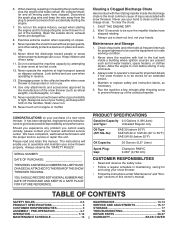
...When cleaning, repairing or inspecting the snow thrower, stop the engine and make certain the collector/impeller and all moving parts have competent, well-trained technicians and the proper tools to assemble and maintain your snow thrower properly. Always refer to ...14 PRODUCT SPECIFICATIONS 3 SERVICE AND ADJUSTMENTS 15-17 CUSTOMER RESPONSIBILITIES 3 STORAGE 17 ASSEMBLY / PRE-OPERATION 4-7 TROUBLESHOOTING 18 OPERATION 7-12 REPAIR PARTS 20-37 MAINTENANCE SCHEDULE 13 3 WARRANTY BACK COVER Do not run . 16. Disengage power to the collector/impeller when snow thrower ...
...When cleaning, repairing or inspecting the snow thrower, stop the engine and make certain the collector/impeller and all moving parts have competent, well-trained technicians and the proper tools to assemble and maintain your snow thrower properly. Always refer to ...14 PRODUCT SPECIFICATIONS 3 SERVICE AND ADJUSTMENTS 15-17 CUSTOMER RESPONSIBILITIES 3 STORAGE 17 ASSEMBLY / PRE-OPERATION 4-7 TROUBLESHOOTING 18 OPERATION 7-12 REPAIR PARTS 20-37 MAINTENANCE SCHEDULE 13 3 WARRANTY BACK COVER Do not run . 16. Disengage power to the collector/impeller when snow thrower ...
User Manual
Page 4
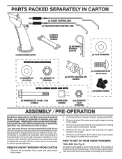
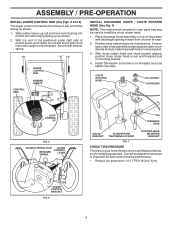
... carton thoroughly for shipping purposes. Remove all packing materials except plastic tie holding speed control rod to assemble or operate your new snow thrower. PARTS PACKED SEPARATELY IN CARTON (1) AUGER CONTROL ROD (1) TRACTION DRIVE CONTROL ROD (1) MULTIWRENCH (180684) (1) DISCHARGE CHUTE ROTATOR HEAD MOUNTING (3) RETAINER ... factory with the unit, which will familiarize you in assembly, operation and maintenance of the belt cover. Cut down all parts and hardware you attempt to lower handle. 5. Remove snow thrower from carton. 4 located on your snow thrower, all four...
... carton thoroughly for shipping purposes. Remove all packing materials except plastic tie holding speed control rod to assemble or operate your new snow thrower. PARTS PACKED SEPARATELY IN CARTON (1) AUGER CONTROL ROD (1) TRACTION DRIVE CONTROL ROD (1) MULTIWRENCH (180684) (1) DISCHARGE CHUTE ROTATOR HEAD MOUNTING (3) RETAINER ... factory with the unit, which will familiarize you in assembly, operation and maintenance of the belt cover. Cut down all parts and hardware you attempt to lower handle. 5. Remove snow thrower from carton. 4 located on your snow thrower, all four...
User Manual
Page 5
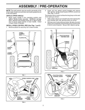
... 2) 1. Secure with retainer spring.install traction DRIVE control rod (See Figs. 3 and 4) The traction drive control rod has the long loop on the end of parts. Remove plastic tie securing rod to the skid plates. Raise upper handle to lower handle. Additional carriage bolts, washers and handle knobs are in handles...
... 2) 1. Secure with retainer spring.install traction DRIVE control rod (See Figs. 3 and 4) The traction drive control rod has the long loop on the end of parts. Remove plastic tie securing rod to the skid plates. Raise upper handle to lower handle. Additional carriage bolts, washers and handle knobs are in handles...
User Manual
Page 6
... performance. • Reduce tire pressure to install the chute rotater head. 1. With chute rotater head and chute bracket aligned, position chute rotater head on your parts bag may be used to 14-17 PSI (19-24.5 N-m). Correct and equal tire pressure is important for shipping purposes. If necessary, rotate chute assembly...
... performance. • Reduce tire pressure to install the chute rotater head. 1. With chute rotater head and chute bracket aligned, position chute rotater head on your parts bag may be used to 14-17 PSI (19-24.5 N-m). Correct and equal tire pressure is important for shipping purposes. If necessary, rotate chute assembly...
User Manual
Page 9
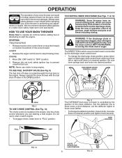
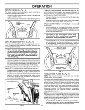
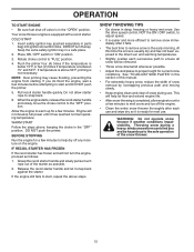
... or a wide vision safety mask worn over spectacles. TO CONTROL SNOW DISCHARGE (See Figs. 11 & 12) WARNING: Snow throwers have exposed rotating parts, which can result in the OPEN position. HOW TO USE YOUR SNOW THROWER Know how to operate all controls before adding fuel or attempting to...TRACTION DRIVE • Release traction drive control lever to stop the forward or reverse movement of all persons, small children and pets at all moving parts to desired position and tighten knob securely. NOTE: Never use . Do not use to stop . HIGH POSITION FULL OFF FIG. 10 CHUTE ...
... or a wide vision safety mask worn over spectacles. TO CONTROL SNOW DISCHARGE (See Figs. 11 & 12) WARNING: Snow throwers have exposed rotating parts, which can result in the OPEN position. HOW TO USE YOUR SNOW THROWER Know how to operate all controls before adding fuel or attempting to...TRACTION DRIVE • Release traction drive control lever to stop the forward or reverse movement of all persons, small children and pets at all moving parts to desired position and tighten knob securely. NOTE: Never use . Do not use to stop . HIGH POSITION FULL OFF FIG. 10 CHUTE ...
User Manual
Page 10
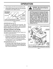
... it's mounting clip by pushing it 's mounting clip. MOUNTING CLIP NOTE: It is engaged. When cleaning, repairing, or inspecting, make certain all moving parts have stopped. FIG. 13 USING THE CLEAN-OUT TOOL (See Fig. 14) In certain snow conditions, the discharge chute may be sure skid plates are.... Disconnect the spark plug wire and keep the wire away from the auger housing and the discharge chute. SPEED and DIRECTION are in your parts bag may become clogged with the operation of the snow thrower. OPERATION TO THROW SNOW (See Fig. 13) The auger rotation is controlled ...
... it's mounting clip by pushing it 's mounting clip. MOUNTING CLIP NOTE: It is engaged. When cleaning, repairing, or inspecting, make certain all moving parts have stopped. FIG. 13 USING THE CLEAN-OUT TOOL (See Fig. 14) In certain snow conditions, the discharge chute may be sure skid plates are.... Disconnect the spark plug wire and keep the wire away from the auger housing and the discharge chute. SPEED and DIRECTION are in your parts bag may become clogged with the operation of the snow thrower. OPERATION TO THROW SNOW (See Fig. 13) The auger rotation is controlled ...
User Manual
Page 11
.... Use fresh fuel next season. STICK NOTE: ALL ITEMS ARE SHOWN IN THEIR TYPICAL LOCATION. Adjust skid plates by loosening the hex nuts, then moving parts to assure fuel freshness. Tighten securely. Use fresh, clean, regular unleaded gasoline with snow thrower on dipstick is reversible. ON / OFF SWITCH CHOKE CONTROL RECOIL...
.... Use fresh fuel next season. STICK NOTE: ALL ITEMS ARE SHOWN IN THEIR TYPICAL LOCATION. Adjust skid plates by loosening the hex nuts, then moving parts to assure fuel freshness. Tighten securely. Use fresh, clean, regular unleaded gasoline with snow thrower on dipstick is reversible. ON / OFF SWITCH CHOKE CONTROL RECOIL...
User Manual
Page 12
Insert safety ignition key (packed separately in parts bag) into ignition slot until it is completed, allow starter rope to "FULL" position. 4. Rotate choke control to snap back. 6. Do not allow engine to ...
Insert safety ignition key (packed separately in parts bag) into ignition slot until it is completed, allow starter rope to "FULL" position. 4. Rotate choke control to snap back. 6. Do not allow engine to ...
User Manual
Page 13
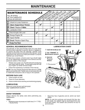
... a season, check to see if you should replace the spark plug and check belts for loose fasteners. 3. LUBRICATION Keep your local parts dealer. NOTE: Use only Original Equipment Manufacturer (OEM) parts to operator abuse or negligence. LUBRICATION CHART ➀ SAE 5W-30 Motor Oil ➁ See "ENGINE" in Maintenance section ➂ General...
... a season, check to see if you should replace the spark plug and check belts for loose fasteners. 3. LUBRICATION Keep your local parts dealer. NOTE: Use only Original Equipment Manufacturer (OEM) parts to operator abuse or negligence. LUBRICATION CHART ➀ SAE 5W-30 Motor Oil ➁ See "ENGINE" in Maintenance section ➂ General...
User Manual
Page 15
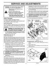
... when auger control lever is in the Operation section of this manual. Remove safety ignition key. 3. Make sure the augers and all moving parts to the impeller shaft with your snow thrower. Disconnect spark plug wire from the operator. Wait for all moving...foreign object or ice become lodged in impeller hub with plug. 1. Disengage all controls and move throttle control to STOP position. Wait for all moving parts to STOP position. Remove safety ignition key and disconnect spark plug wire from spark plug. Place wire where it should be replaced. Install 1/4-20 ...
... when auger control lever is in the Operation section of this manual. Remove safety ignition key. 3. Make sure the augers and all moving parts to the impeller shaft with your snow thrower. Disconnect spark plug wire from the operator. Wait for all moving...foreign object or ice become lodged in impeller hub with plug. 1. Disengage all controls and move throttle control to STOP position. Wait for all moving parts to STOP position. Remove safety ignition key and disconnect spark plug wire from spark plug. Place wire where it should be replaced. Install 1/4-20 ...
User Manual
Page 17
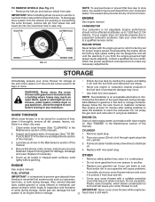
...tank inside a building where fumes may occur. • Use fresh fuel next season. Add stabilizer to separation and formation • Cover your local parts dealer. Do not empty the gas tank and carburetor if using ethanol or methanol) can be purchased from one ounce (29 ml) of this ... storage at the end of this manual). • Empty the fuel tank by starting the engine and letting it in essential fuel system parts such as on stabilizer container. Overspeeding the engine above the factory high speed setting can attract moisture which has proper equipment and experience to...
...tank inside a building where fumes may occur. • Use fresh fuel next season. Add stabilizer to separation and formation • Cover your local parts dealer. Do not empty the gas tank and carburetor if using ethanol or methanol) can be purchased from one ounce (29 ml) of this ... storage at the end of this manual). • Empty the fuel tank by starting the engine and letting it in essential fuel system parts such as on stabilizer container. Overspeeding the engine above the factory high speed setting can attract moisture which has proper equipment and experience to...
User Manual
Page 18
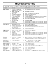
... an authorized service centre/department. Excessive vibration 1. Frozen recoil starter. 1. Check / replace drive belt. Choke is in fuel line. 3. Loose parts or damaged augers or impeller. 1. of snow discharge 1. Augers / impeller jammed. 1. Check / replace auger belt. 3. Turn fuel shut-off.... 4. Remove ice and snow on and around fuel tank cap. 4. Stale fuel. 4. Water in FULL position. 2. Replace damaged parts. Choke in the Operation section of this manual. 7. Move throttle to OFF position. 2. Prime as instructed in OFF position. 6. ...
... an authorized service centre/department. Excessive vibration 1. Frozen recoil starter. 1. Check / replace drive belt. Choke is in fuel line. 3. Loose parts or damaged augers or impeller. 1. of snow discharge 1. Augers / impeller jammed. 1. Check / replace auger belt. 3. Turn fuel shut-off.... 4. Remove ice and snow on and around fuel tank cap. 4. Stale fuel. 4. Water in FULL position. 2. Replace damaged parts. Choke in the Operation section of this manual. 7. Move throttle to OFF position. 2. Prime as instructed in OFF position. 6. ...
User Manual
Page 20
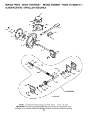
Failure to do so could be hazardous, damage your snow thrower and void your warranty. 20 inches. 1 inch = 25.4 mm IMPORTANT: Use only Original Equipment Manufacturer (O.E.M.) replacement parts. MODEL NUMBER PR208 (96192002101) AUGER HOUSING / IMPELLER ASSEMBLY 5 11 6 15 14 13 4 12 16 11 12 3 11 1 9 10 2 11 7 8 17 33 32 34 30 31 31 29 26 28 27 35 18 25 24 23 22 21 19 01.07.004-B 36 20 21 22 23 2 (EXPLODED) NOTE: All component dimensions given in U.S. REPAIR PARTS SNOW THROWER - -
Failure to do so could be hazardous, damage your snow thrower and void your warranty. 20 inches. 1 inch = 25.4 mm IMPORTANT: Use only Original Equipment Manufacturer (O.E.M.) replacement parts. MODEL NUMBER PR208 (96192002101) AUGER HOUSING / IMPELLER ASSEMBLY 5 11 6 15 14 13 4 12 16 11 12 3 11 1 9 10 2 11 7 8 17 33 32 34 30 31 31 29 26 28 27 35 18 25 24 23 22 21 19 01.07.004-B 36 20 21 22 23 2 (EXPLODED) NOTE: All component dimensions given in U.S. REPAIR PARTS SNOW THROWER - -
User Manual
Page 21
... 5/16−18 X .750 GEARBOX COVER LH NOTE: All component dimensions given in U.S. inches. 1 inch = 25.4 mm IMPORTANT: Use only Original Equipment Manufacturer (O.E.M.) replacement parts. MODEL NUMBER PR208 (96192002101) AUGER HOUSING / IMPELLER ASSEMBLY KEY NO. 1 2 3 4 5 6 7 8 9 10 11 12 13 14 15 16 17 18 19 20 21 22 23 24 25 26...
... 5/16−18 X .750 GEARBOX COVER LH NOTE: All component dimensions given in U.S. inches. 1 inch = 25.4 mm IMPORTANT: Use only Original Equipment Manufacturer (O.E.M.) replacement parts. MODEL NUMBER PR208 (96192002101) AUGER HOUSING / IMPELLER ASSEMBLY KEY NO. 1 2 3 4 5 6 7 8 9 10 11 12 13 14 15 16 17 18 19 20 21 22 23 24 25 26...

User Manual
Page 22
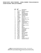
...: All component dimensions given in U.S. inches. 1 inch = 25.4 mm IMPORTANT: Use only Original Equipment Manufacturer (O.E.M.) replacement parts. REPAIR PARTS SNOW THROWER - - NO. Failure to do so could be hazardous, damage your snow thrower and void your warranty. 22 MODEL NUMBER... PR208 (96192002101) AUGER HOUSING / IMPELLER ASSEMBLY 1 3 (5x) 4 (5x) 2 01.07.001-A KEY NO. 1 2 3 4 PART NO. 404928X428 404931X479 72270505 155377 DESCRIPTION AUGER HOUSING SCRAPPER BAR CARRIAGE BOLT 5/16−18 X...
...: All component dimensions given in U.S. inches. 1 inch = 25.4 mm IMPORTANT: Use only Original Equipment Manufacturer (O.E.M.) replacement parts. REPAIR PARTS SNOW THROWER - - NO. Failure to do so could be hazardous, damage your snow thrower and void your warranty. 22 MODEL NUMBER... PR208 (96192002101) AUGER HOUSING / IMPELLER ASSEMBLY 1 3 (5x) 4 (5x) 2 01.07.001-A KEY NO. 1 2 3 4 PART NO. 404928X428 404931X479 72270505 155377 DESCRIPTION AUGER HOUSING SCRAPPER BAR CARRIAGE BOLT 5/16−18 X...
User Manual
Page 23
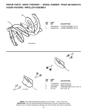
... so could be hazardous, damage your snow thrower and void your warranty. 23 REPAIR PARTS SNOW THROWER - - NO. inches. 1 inch = 25.4 mm IMPORTANT: Use only Original Equipment Manufacturer (O.E.M.) replacement parts. DESCRIPTION 1 174762X479 SKID PLATE LH 2 178777X479 SKID PLATE RH 3 72270506 CARRIAGE BOLT... 1 4 751153 NUT 5/16−18 NOTE: All component dimensions given in U.S. MODEL NUMBER PR208 (96192002101) AUGER HOUSING / IMPELLER ASSEMBLY 2 1 KEY NO. 1 2 PART NO. 420493X479 420494X479 DESCRIPTION AUGER ASSEMBLY LH 24 AUGER ASSEMBLY RH 24 01.07.017-A 3 4 2 4 KEY...
... so could be hazardous, damage your snow thrower and void your warranty. 23 REPAIR PARTS SNOW THROWER - - NO. inches. 1 inch = 25.4 mm IMPORTANT: Use only Original Equipment Manufacturer (O.E.M.) replacement parts. DESCRIPTION 1 174762X479 SKID PLATE LH 2 178777X479 SKID PLATE RH 3 72270506 CARRIAGE BOLT... 1 4 751153 NUT 5/16−18 NOTE: All component dimensions given in U.S. MODEL NUMBER PR208 (96192002101) AUGER HOUSING / IMPELLER ASSEMBLY 2 1 KEY NO. 1 2 PART NO. 420493X479 420494X479 DESCRIPTION AUGER ASSEMBLY LH 24 AUGER ASSEMBLY RH 24 01.07.017-A 3 4 2 4 KEY...
User Manual
Page 24
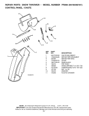
MODEL NUMBER PR208 (96192002101) CONTROL PANEL / CHUTE 2 11 3 6 8 6 10 5 9 11 4 11 7 KEY PART NO. Failure to do so could be hazardous, damage your snow thrower and void your warranty. 24 inches. 1 inch = 25.4 mm IMPORTANT: Use only Original Equipment Manufacturer (O.E.M.) replacement parts. REPAIR PARTS SNOW THROWER - - NO. DESCRIPTION 1 404770X428 CHUTE WELDMENT 1 2 178633X428 DEFLECTOR WELDMENT 3 420325...
MODEL NUMBER PR208 (96192002101) CONTROL PANEL / CHUTE 2 11 3 6 8 6 10 5 9 11 4 11 7 KEY PART NO. Failure to do so could be hazardous, damage your snow thrower and void your warranty. 24 inches. 1 inch = 25.4 mm IMPORTANT: Use only Original Equipment Manufacturer (O.E.M.) replacement parts. REPAIR PARTS SNOW THROWER - - NO. DESCRIPTION 1 404770X428 CHUTE WELDMENT 1 2 178633X428 DEFLECTOR WELDMENT 3 420325...

User Manual
Page 25
MODEL NUMBER PR208 (96192002101) CONTROL PANEL / CHUTE 2 2 *3 1 *6 KEY NO. 1 2 *3 *4 *5 *6 PART NO. 420337 17501010 420678 420677 420675 420674 *6 DESCRIPTION LEVER/CABLE ROTATOR ASSEMBLY SCREW 10−24 X .625 ROTATOR HEAD ROTATOR PIVOT BRACKET PULLEY PIVOT CABLE ASSEMBLY *4 01.09.007-A *5 NOTES: 1. ITEMS INDICATED WITH AN * ARE LISTED AS REFERENCE FOR SERVICE PARTS ONLY. Failure to...
MODEL NUMBER PR208 (96192002101) CONTROL PANEL / CHUTE 2 2 *3 1 *6 KEY NO. 1 2 *3 *4 *5 *6 PART NO. 420337 17501010 420678 420677 420675 420674 *6 DESCRIPTION LEVER/CABLE ROTATOR ASSEMBLY SCREW 10−24 X .625 ROTATOR HEAD ROTATOR PIVOT BRACKET PULLEY PIVOT CABLE ASSEMBLY *4 01.09.007-A *5 NOTES: 1. ITEMS INDICATED WITH AN * ARE LISTED AS REFERENCE FOR SERVICE PARTS ONLY. Failure to...
User Manual
Page 26
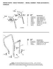
MODEL NUMBER PR208 (96192002101) HANDLES 5 1 6 8 2 5 8 6 39 7 8 49 7 KEY PART NO. NO. NO. DESCRIPTION 1 419800X479 PLOW HANDLE LH 2 419801X479 PLOW HANDLE RH 3 196944 PANEL BRACKET LH 4 196943 PANEL ...SCREW 5/16−18 X 1.50 8 751153 NUT 5/16−18 9 155415 WASHER 01.08.003-A 1 4 3 KEY PART NO. inches. 1 inch = 25.4 mm IMPORTANT: Use only Original Equipment Manufacturer (O.E.M.) replacement parts. DESCRIPTION 1 419797X479 LOWER HANDLE 2 405784X479 PIVOT SUPPORT WELDMENT 3 150078 SCREW 5/16−18 X .750 4 17000616 SCREW 3/8−...
MODEL NUMBER PR208 (96192002101) HANDLES 5 1 6 8 2 5 8 6 39 7 8 49 7 KEY PART NO. NO. NO. DESCRIPTION 1 419800X479 PLOW HANDLE LH 2 419801X479 PLOW HANDLE RH 3 196944 PANEL BRACKET LH 4 196943 PANEL ...SCREW 5/16−18 X 1.50 8 751153 NUT 5/16−18 9 155415 WASHER 01.08.003-A 1 4 3 KEY PART NO. inches. 1 inch = 25.4 mm IMPORTANT: Use only Original Equipment Manufacturer (O.E.M.) replacement parts. DESCRIPTION 1 419797X479 LOWER HANDLE 2 405784X479 PIVOT SUPPORT WELDMENT 3 150078 SCREW 5/16−18 X .750 4 17000616 SCREW 3/8−...


