
User Manual
Page 2
...remove gas-powered equipment Vibration is for any damage, and repair the damage before filling. 4. WARNING: Snow throwers have exposed rotating parts, which can get caught in order to prevent accidental starting motors. 6. CAUTION: Muffler and other reproductive harm. Adjust the collector ...height to observe the following safety instructions could result in reverse. Do not put hands or feet near or under rotating parts. YOUR SAFETY IS INVOLVED. Preparation 1. Always place restarting and operating the snow thrower. IMPORTANT Safe Operation Practices for this...
...remove gas-powered equipment Vibration is for any damage, and repair the damage before filling. 4. WARNING: Snow throwers have exposed rotating parts, which can get caught in order to prevent accidental starting motors. 6. CAUTION: Muffler and other reproductive harm. Adjust the collector ...height to observe the following safety instructions could result in reverse. Do not put hands or feet near or under rotating parts. YOUR SAFETY IS INVOLVED. Preparation 1. Always place restarting and operating the snow thrower. IMPORTANT Safe Operation Practices for this...
User Manual
Page 3
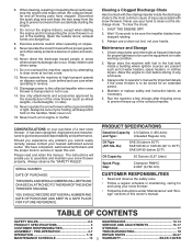
...PRODUCT SPECIFICATIONS 3 SERVICE AND ADJUSTMENTS 15-17 CUSTOMER RESPONSIBILITIES 3 STORAGE 17 ASSEMBLY / PRE-OPERATION 4-7 TROUBLESHOOTING 18 OPERATION 7-12 REPAIR PARTS 20-37 MAINTENANCE SCHEDULE 13 3 WARRANTY BACK COVER Do not overload the machine capacity by the manufacturer of the collector/impeller. ... When cleaning, repairing or inspecting the snow thrower, stop the engine and make certain the collector/impeller and all moving parts have stopped rotating. 3. It has been designed, engineered and manufactured to be sure the equipment is in the fuel ...
...PRODUCT SPECIFICATIONS 3 SERVICE AND ADJUSTMENTS 15-17 CUSTOMER RESPONSIBILITIES 3 STORAGE 17 ASSEMBLY / PRE-OPERATION 4-7 TROUBLESHOOTING 18 OPERATION 7-12 REPAIR PARTS 20-37 MAINTENANCE SCHEDULE 13 3 WARRANTY BACK COVER Do not overload the machine capacity by the manufacturer of the collector/impeller. ... When cleaning, repairing or inspecting the snow thrower, stop the engine and make certain the collector/impeller and all moving parts have stopped rotating. 3. It has been designed, engineered and manufactured to be sure the equipment is in the fuel ...
User Manual
Page 4
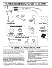
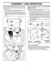
...to ensure proper tightness. 2. Reading the entire manual will familiarize you with the exception of those parts left unassembled for additional loose parts. Cut down all parts and hardware you attempt to complete the assembly have been placed in the toolbox. Your new ... thrower has been assembled at the factory with the unit, which will assist you in its entirety before you assemble must be tightened securely. PARTS PACKED SEPARATELY IN CARTON (1) AUGER CONTROL ROD (1) TRACTION DRIVE CONTROL ROD (1) MULTIWRENCH (180684) (1) DISCHARGE CHUTE ROTATOR HEAD MOUNTING (3) RETAINER ...
...to ensure proper tightness. 2. Reading the entire manual will familiarize you with the exception of those parts left unassembled for additional loose parts. Cut down all parts and hardware you attempt to complete the assembly have been placed in the toolbox. Your new ... thrower has been assembled at the factory with the unit, which will assist you in its entirety before you assemble must be tightened securely. PARTS PACKED SEPARATELY IN CARTON (1) AUGER CONTROL ROD (1) TRACTION DRIVE CONTROL ROD (1) MULTIWRENCH (180684) (1) DISCHARGE CHUTE ROTATOR HEAD MOUNTING (3) RETAINER ...
User Manual
Page 5
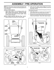
... CONTROL LEVER RETAINER SPRING DRIVE CONTROL BRACKET FIG. 4 TRACTION DRIVE CONTROL ROD ASSEMBLY / PRE-OPERATION NOTE: The multi-wrench may be used for assembly of parts. Additional carriage bolts, washers and handle knobs are in bag of the chute rotator head to snow thrower and making adjustments to the operating position...
... CONTROL LEVER RETAINER SPRING DRIVE CONTROL BRACKET FIG. 4 TRACTION DRIVE CONTROL ROD ASSEMBLY / PRE-OPERATION NOTE: The multi-wrench may be used for assembly of parts. Additional carriage bolts, washers and handle knobs are in bag of the chute rotator head to snow thrower and making adjustments to the operating position...
User Manual
Page 6
... loop opening toward front of spring into hole in auger control bracket. Position chute rotater head over chute bracket. Install 3/8 washer and locknut on your parts bag may be used to 14-17 PSI (19-24.5 N-m). Correct and equal tire pressure is important for shipping purposes. Place discharge chute assembly on...
... loop opening toward front of spring into hole in auger control bracket. Position chute rotater head over chute bracket. Install 3/8 washer and locknut on your parts bag may be used to 14-17 PSI (19-24.5 N-m). Correct and equal tire pressure is important for shipping purposes. Place discharge chute assembly on...
User Manual
Page 9
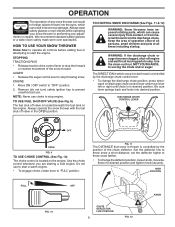
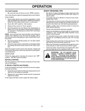
...1. NOTE: Never use to stop throwing snow. TO CONTROL SNOW DISCHARGE (See Figs. 11 & 12) WARNING: Snow throwers have exposed rotating parts, which can cause severe injury from contact, or from material thrown from the discharge chute. ward on discharge chute control lever and move deflector ... a wide vision safety mask worn over spectacles. Keep the area of operation clear of all persons, small children and pets at all moving parts to "FULL" position. WARNING: If the discharge chute or auger become clogged, shut-off valve in desired position. OPERATION The operation of...
...1. NOTE: Never use to stop throwing snow. TO CONTROL SNOW DISCHARGE (See Figs. 11 & 12) WARNING: Snow throwers have exposed rotating parts, which can cause severe injury from contact, or from material thrown from the discharge chute. ward on discharge chute control lever and move deflector ... a wide vision safety mask worn over spectacles. Keep the area of operation clear of all persons, small children and pets at all moving parts to "FULL" position. WARNING: If the discharge chute or auger become clogged, shut-off valve in desired position. OPERATION The operation of...
User Manual
Page 10
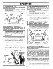
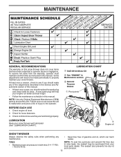
...springs back and locks into the discharge chute to lowest (highest scraper clearance) position. When cleaning, repairing, or inspecting, make certain all moving parts have stopped. CAUTION: Do not move lever to operate the snow thrower over gravel surface, use a slower speed until you are controlled by... TO MOVE FORWARD AND BACKWARD (See Fig. 15) SELF-PROPELLING, forward and reverse movement of the snow thrower, is pointed in your parts bag may become clogged with the operation of the snow thrower. It is uneven. DISCHARGE CHUTE CLEAN-OUT TOOL DRIVE SPEED CONTROL LEVER FIG...
...springs back and locks into the discharge chute to lowest (highest scraper clearance) position. When cleaning, repairing, or inspecting, make certain all moving parts have stopped. CAUTION: Do not move lever to operate the snow thrower over gravel surface, use a slower speed until you are controlled by... TO MOVE FORWARD AND BACKWARD (See Fig. 15) SELF-PROPELLING, forward and reverse movement of the snow thrower, is pointed in your parts bag may become clogged with the operation of the snow thrower. It is uneven. DISCHARGE CHUTE CLEAN-OUT TOOL DRIVE SPEED CONTROL LEVER FIG...
User Manual
Page 11
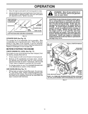
OPERATION 1. Adjust skid plates by loosening the hex nuts, then moving parts to separation and formation of the housing, it run until "FULL" mark on your snow thrower has been shipped, from the factory, already filled with a ...
OPERATION 1. Adjust skid plates by loosening the hex nuts, then moving parts to separation and formation of the housing, it run until "FULL" mark on your snow thrower has been shipped, from the factory, already filled with a ...
User Manual
Page 12
.... • Adjust the skid plates to remove snow is easier and more efficient to start , repeat the above steps. See "TO ADJUST SKID PLATES" in parts bag) into ignition slot until it clicks. Insert safety ignition key (packed separately in this section of this time the snow is usually dry and...
.... • Adjust the skid plates to remove snow is easier and more efficient to start , repeat the above steps. See "TO ADJUST SKID PLATES" in parts bag) into ignition slot until it clicks. Insert safety ignition key (packed separately in this section of this time the snow is usually dry and...
User Manual
Page 13
... least once a year, you should replace the spark plug and check belts for loose fasteners. 3. Some adjustments will help your local parts dealer. NOTE: Use only Original Equipment Manufacturer (OEM) parts to service this snow thrower does not cover items that have been subjected to do so can harm rubber. Check for...
... least once a year, you should replace the spark plug and check belts for loose fasteners. 3. Some adjustments will help your local parts dealer. NOTE: Use only Original Equipment Manufacturer (OEM) parts to service this snow thrower does not cover items that have been subjected to do so can harm rubber. Check for...
User Manual
Page 15
...stop . 2. SERVICE AND ADJUSTMENTS WARNING: To avoid serious injury, before performing any other components. Make sure the augers and all moving parts to any other com- CAUTION: Do not substitute. Connect spark plug wire to any service or adjustments: 1. Should a foreign object...SNOW DISCHARGE" in the OFF position. 2. Remove safety ignition key. 3. Disconnect spark plug wire from the operator. Disengage all moving parts have sheared. Wait for all controls and move throttle control to STOP position. Use only original equipment capscrew/shear bolts as supplied with...
...stop . 2. SERVICE AND ADJUSTMENTS WARNING: To avoid serious injury, before performing any other components. Make sure the augers and all moving parts to any other com- CAUTION: Do not substitute. Connect spark plug wire to any service or adjustments: 1. Should a foreign object...SNOW DISCHARGE" in the OFF position. 2. Remove safety ignition key. 3. Disconnect spark plug wire from the operator. Disengage all moving parts have sheared. Wait for all controls and move throttle control to STOP position. Use only original equipment capscrew/shear bolts as supplied with...
User Manual
Page 17
... and corrosion. ENGINE SPEED Never tamper with the engine governor, which leads to separation and formation • Cover your local parts dealer. WARNING: Never store the snow thrower with new spark plug. Store in fuel tank or storage container. Clean entire snow... Drain oil (with engine warm) and replace with a suitable protective cover that all rusted or chipped paint surfaces; CYLINDER 2. Inspect moving parts for proper engine speed. Replace if necessary. 5. sand lightly before storing in minimizing the formation of this manual). 3. Pull recoil starter ...
... and corrosion. ENGINE SPEED Never tamper with the engine governor, which leads to separation and formation • Cover your local parts dealer. WARNING: Never store the snow thrower with new spark plug. Store in fuel tank or storage container. Clean entire snow... Drain oil (with engine warm) and replace with a suitable protective cover that all rusted or chipped paint surfaces; CYLINDER 2. Inspect moving parts for proper engine speed. Replace if necessary. 5. sand lightly before storing in minimizing the formation of this manual). 3. Pull recoil starter ...
User Manual
Page 18
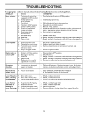
...2. Prime as instructed in the Operation section of this manual. Throwing too much snow. 3. Dirty or clogged muffler. 1. Stale fuel. 4. Loose parts or damaged augers or impeller. 1. Loss of drive speed 3. Drive belt is off valve (if so equipped) in fuel line. 3. of traction... Fill fuel tank with fresh, clean gasoline. 11. Wait a few minutes before restarting, DO NOT prime. 8. Reconnect spark plug wire. 2. Replace damaged parts. drive / slowing 2. Loss of snow discharge or slowing of fuel. 4. Check / reinstall auger belt. 2. Bad spark plug. 10. Fuel tank cap...
...2. Prime as instructed in the Operation section of this manual. Throwing too much snow. 3. Dirty or clogged muffler. 1. Stale fuel. 4. Loose parts or damaged augers or impeller. 1. Loss of drive speed 3. Drive belt is off valve (if so equipped) in fuel line. 3. of traction... Fill fuel tank with fresh, clean gasoline. 11. Wait a few minutes before restarting, DO NOT prime. 8. Reconnect spark plug wire. 2. Replace damaged parts. drive / slowing 2. Loss of snow discharge or slowing of fuel. 4. Check / reinstall auger belt. 2. Bad spark plug. 10. Fuel tank cap...
User Manual
Page 20
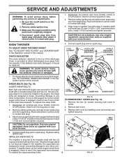
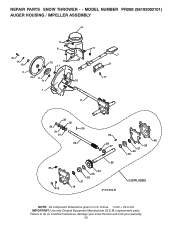
MODEL NUMBER PR208 (96192002101) AUGER HOUSING / IMPELLER ASSEMBLY 5 11 6 15 14 13 4 12 16 11 12 3 11 1 9 10 2 11 7 8 17 33 32 34 30 31 31 29 26 28 27 35 18 25 24 23 22 21 19 01.07.004-B 36 20 21 22 23 2 (EXPLODED) NOTE: All component dimensions given in U.S. Failure to do so could be hazardous, damage your snow thrower and void your warranty. 20 REPAIR PARTS SNOW THROWER - - inches. 1 inch = 25.4 mm IMPORTANT: Use only Original Equipment Manufacturer (O.E.M.) replacement parts.
MODEL NUMBER PR208 (96192002101) AUGER HOUSING / IMPELLER ASSEMBLY 5 11 6 15 14 13 4 12 16 11 12 3 11 1 9 10 2 11 7 8 17 33 32 34 30 31 31 29 26 28 27 35 18 25 24 23 22 21 19 01.07.004-B 36 20 21 22 23 2 (EXPLODED) NOTE: All component dimensions given in U.S. Failure to do so could be hazardous, damage your snow thrower and void your warranty. 20 REPAIR PARTS SNOW THROWER - - inches. 1 inch = 25.4 mm IMPORTANT: Use only Original Equipment Manufacturer (O.E.M.) replacement parts.
User Manual
Page 21
...: All component dimensions given in U.S. inches. 1 inch = 25.4 mm IMPORTANT: Use only Original Equipment Manufacturer (O.E.M.) replacement parts. Failure to do so could be hazardous, damage your snow thrower and void your warranty. 21 MODEL NUMBER PR208 (96192002101) AUGER HOUSING / IMPELLER ASSEMBLY KEY NO. 1 2 3 4 5 6 7 8 9 10 11 12 13 ...14 15 16 17 18 19 20 21 22 23 24 25 26 27 28 29 30 31 32 33 34 35 36 PART NO. REPAIR PARTS SNOW THROWER - -
...: All component dimensions given in U.S. inches. 1 inch = 25.4 mm IMPORTANT: Use only Original Equipment Manufacturer (O.E.M.) replacement parts. Failure to do so could be hazardous, damage your snow thrower and void your warranty. 21 MODEL NUMBER PR208 (96192002101) AUGER HOUSING / IMPELLER ASSEMBLY KEY NO. 1 2 3 4 5 6 7 8 9 10 11 12 13 ...14 15 16 17 18 19 20 21 22 23 24 25 26 27 28 29 30 31 32 33 34 35 36 PART NO. REPAIR PARTS SNOW THROWER - -

User Manual
Page 22
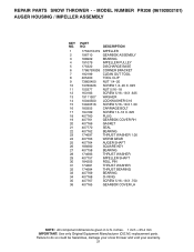
... PLUG 3 179582 SCREW 5/16−18 X 1.00 01.07.024-B NOTE: All component dimensions given in U.S. REPAIR PARTS SNOW THROWER - - MODEL NUMBER PR208 (96192002101) AUGER HOUSING / IMPELLER ASSEMBLY 1 3 (5x) 4 (5x) 2 01.07.001-A KEY NO. 1 2 3 4 PART NO. 404928X428 404931X479 72270505 155377 DESCRIPTION AUGER HOUSING SCRAPPER BAR CARRIAGE BOLT 5/16−18 X .625 NUT...
... PLUG 3 179582 SCREW 5/16−18 X 1.00 01.07.024-B NOTE: All component dimensions given in U.S. REPAIR PARTS SNOW THROWER - - MODEL NUMBER PR208 (96192002101) AUGER HOUSING / IMPELLER ASSEMBLY 1 3 (5x) 4 (5x) 2 01.07.001-A KEY NO. 1 2 3 4 PART NO. 404928X428 404931X479 72270505 155377 DESCRIPTION AUGER HOUSING SCRAPPER BAR CARRIAGE BOLT 5/16−18 X .625 NUT...
User Manual
Page 23
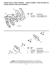
... PLATE RH 3 72270506 CARRIAGE BOLT 5/16−18 X .75 3 01.11.001-A 1 4 751153 NUT 5/16−18 NOTE: All component dimensions given in U.S. MODEL NUMBER PR208 (96192002101) AUGER HOUSING / IMPELLER ASSEMBLY 2 1 KEY NO. 1 2 PART NO. 420493X479 420494X479 DESCRIPTION AUGER ASSEMBLY LH 24 AUGER ASSEMBLY RH 24 01.07.017-A 3 4 2 4 KEY...
... PLATE RH 3 72270506 CARRIAGE BOLT 5/16−18 X .75 3 01.11.001-A 1 4 751153 NUT 5/16−18 NOTE: All component dimensions given in U.S. MODEL NUMBER PR208 (96192002101) AUGER HOUSING / IMPELLER ASSEMBLY 2 1 KEY NO. 1 2 PART NO. 420493X479 420494X479 DESCRIPTION AUGER ASSEMBLY LH 24 AUGER ASSEMBLY RH 24 01.07.017-A 3 4 2 4 KEY...
User Manual
Page 24
inches. 1 inch = 25.4 mm IMPORTANT: Use only Original Equipment Manufacturer (O.E.M.) replacement parts. DESCRIPTION 1 404770X428 CHUTE WELDMENT 1 2 178633X428 DEFLECTOR WELDMENT 3 420325 DEFLECTOR SEAL 4 179096X479 STRAP 5 189713X479 KNOB BLACK 6 128415 POP RIVET 7 185600 ...155415 WASHER 11 179246 PLASTIC WASHER 01.09.001-A NOTE: All component dimensions given in U.S. MODEL NUMBER PR208 (96192002101) CONTROL PANEL / CHUTE 2 11 3 6 8 6 10 5 9 11 4 11 7 KEY PART NO. Failure to do so could be hazardous, damage your snow thrower and void your warranty. 24 NO...
inches. 1 inch = 25.4 mm IMPORTANT: Use only Original Equipment Manufacturer (O.E.M.) replacement parts. DESCRIPTION 1 404770X428 CHUTE WELDMENT 1 2 178633X428 DEFLECTOR WELDMENT 3 420325 DEFLECTOR SEAL 4 179096X479 STRAP 5 189713X479 KNOB BLACK 6 128415 POP RIVET 7 185600 ...155415 WASHER 11 179246 PLASTIC WASHER 01.09.001-A NOTE: All component dimensions given in U.S. MODEL NUMBER PR208 (96192002101) CONTROL PANEL / CHUTE 2 11 3 6 8 6 10 5 9 11 4 11 7 KEY PART NO. Failure to do so could be hazardous, damage your snow thrower and void your warranty. 24 NO...

User Manual
Page 25
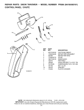
MODEL NUMBER PR208 (96192002101) CONTROL PANEL / CHUTE 2 2 *3 1 *6 KEY NO. 1 2 *3 *4 *5 *6 PART NO. 420337 17501010 420678 420677 420675 420674 *6 DESCRIPTION LEVER/CABLE ROTATOR ASSEMBLY SCREW 10−24 X .625 ROTATOR HEAD ROTATOR PIVOT BRACKET PULLEY PIVOT CABLE ASSEMBLY *4 01.09.007-A *5 NOTES: 1. NOTE: All component dimensions given in U.S. REPAIR PARTS SNOW THROWER - - ITEMS INDICATED WITH AN...
MODEL NUMBER PR208 (96192002101) CONTROL PANEL / CHUTE 2 2 *3 1 *6 KEY NO. 1 2 *3 *4 *5 *6 PART NO. 420337 17501010 420678 420677 420675 420674 *6 DESCRIPTION LEVER/CABLE ROTATOR ASSEMBLY SCREW 10−24 X .625 ROTATOR HEAD ROTATOR PIVOT BRACKET PULLEY PIVOT CABLE ASSEMBLY *4 01.09.007-A *5 NOTES: 1. NOTE: All component dimensions given in U.S. REPAIR PARTS SNOW THROWER - - ITEMS INDICATED WITH AN...
User Manual
Page 26
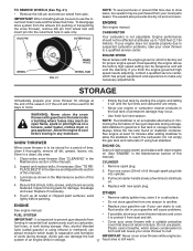
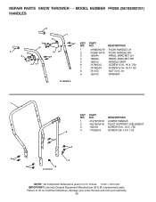
MODEL NUMBER PR208 (96192002101) HANDLES 5 1 6 8 2 5 8 6 39 7 8 49 7 KEY PART NO. NO. DESCRIPTION 1 419797X479 LOWER HANDLE 2 405784X479 PIVOT SUPPORT WELDMENT 3 150078 SCREW 5/16−18 X .750 4 17000616 SCREW 3/8−16 X 1.00 2 4 ..., damage your snow thrower and void your warranty. 26 NO. inches. 1 inch = 25.4 mm IMPORTANT: Use only Original Equipment Manufacturer (O.E.M.) replacement parts. DESCRIPTION 1 419800X479 PLOW HANDLE LH 2 419801X479 PLOW HANDLE RH 3 196944 PANEL BRACKET LH 4 196943 PANEL BRACKET RH 5 199513 HANDLE GRIP 6 74780512...
MODEL NUMBER PR208 (96192002101) HANDLES 5 1 6 8 2 5 8 6 39 7 8 49 7 KEY PART NO. NO. DESCRIPTION 1 419797X479 LOWER HANDLE 2 405784X479 PIVOT SUPPORT WELDMENT 3 150078 SCREW 5/16−18 X .750 4 17000616 SCREW 3/8−16 X 1.00 2 4 ..., damage your snow thrower and void your warranty. 26 NO. inches. 1 inch = 25.4 mm IMPORTANT: Use only Original Equipment Manufacturer (O.E.M.) replacement parts. DESCRIPTION 1 419800X479 PLOW HANDLE LH 2 419801X479 PLOW HANDLE RH 3 196944 PANEL BRACKET LH 4 196943 PANEL BRACKET RH 5 199513 HANDLE GRIP 6 74780512...


