
Owner's Manual
Page 5
...amping your front speakers 55 Bi-wiring your speakers 55 Connecting additional amplifiers 56 Using this receiver with a Pioneer plasma display 56 Using the SR+ mode with a Pioneer plasma display 57 12 Other Settings The Input Assign menu 58 The Other Setup menu 59 Dynamic Range ...Dual Mono Setup 60 LFE Attenuator Setup 60 SR+ Setup for Pioneer plasma displays . . . 60 13 Additional information Troubleshooting 61 XM radio messages 63 Resetting the main unit 63 Switching the speaker impedance 63 Specifications 64 Power cord caution 65 Cleaning the unit 65 English Italiano Fran...
...amping your front speakers 55 Bi-wiring your speakers 55 Connecting additional amplifiers 56 Using this receiver with a Pioneer plasma display 56 Using the SR+ mode with a Pioneer plasma display 57 12 Other Settings The Input Assign menu 58 The Other Setup menu 59 Dynamic Range ...Dual Mono Setup 60 LFE Attenuator Setup 60 SR+ Setup for Pioneer plasma displays . . . 60 13 Additional information Troubleshooting 61 XM radio messages 63 Resetting the main unit 63 Switching the speaker impedance 63 Specifications 64 Power cord caution 65 Cleaning the unit 65 English Italiano Fran...
Owner's Manual
Page 35
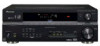
... if you 'll have already completed Automatically setting up for your front speakers on page 54). • Front Bi-Amp - The last five settings are specifically for normal home theater use the (surround back) B speaker terminals to listen to the overall balance of your speaker system (see Setting the Acoustic Calibration...
... if you 'll have already completed Automatically setting up for your front speakers on page 54). • Front Bi-Amp - The last five settings are specifically for normal home theater use the (surround back) B speaker terminals to listen to the overall balance of your speaker system (see Setting the Acoustic Calibration...
Owner's Manual
Page 64
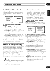
13 Additional information Specifications Amplifier section • Continuous power output (stereo) Front. . 110 W (20 to 20 000 Hz, THD 0.7 %, 8 Ω)1 • Continuous power output (surround) Front. . . . . 110 W per channel (1 ...
13 Additional information Specifications Amplifier section • Continuous power output (stereo) Front. . 110 W (20 to 20 000 Hz, THD 0.7 %, 8 Ω)1 • Continuous power output (surround) Front. . . . . 110 W per channel (1 ...

Owner's Manual
Page 65
...AM Tuner Section Frequency Range 530 kHz to 1700 kHz Sensitivity (IHF, Loop antenna 350 µV/m Signal-to be stepped on. Note • Specifications and the design are subject to possible modifications without package 20.3 lb (9.2 kg) Furnished Parts Microphone (for a replacement. 65 En Never make ...a knot in the cord or tie it damaged, ask your nearest Pioneer authorized service center or your hands are not likely to -Noise Ratio 50 dB Antenna Loop antenna Miscellaneous Power requirements AC 120V / 60Hz Power...
...AM Tuner Section Frequency Range 530 kHz to 1700 kHz Sensitivity (IHF, Loop antenna 350 µV/m Signal-to be stepped on. Note • Specifications and the design are subject to possible modifications without package 20.3 lb (9.2 kg) Furnished Parts Microphone (for a replacement. 65 En Never make ...a knot in the cord or tie it damaged, ask your nearest Pioneer authorized service center or your hands are not likely to -Noise Ratio 50 dB Antenna Loop antenna Miscellaneous Power requirements AC 120V / 60Hz Power...
Owner's Manual
Page 67
... send it will take any remedies, created by a traceable, insured method, to resolve the dispute. You are experiencing, steps you and Pioneer, Pioneer makes available its Complaint Resolution Program to an Authorized Service Company. or (2) respond to you what time period, to some models. The...WHICH WOULD BE OTHERWISE PROVIDED WITHOUT CHARGE UNDER THIS WARRANTY OBTAINED FROM ANY SOURCE OTHER THAN A PIONEER AUTHORIZED SERVICE COMPANY OR OTHER DESIGNATED LOCATION. THIS WARRANTY GIVES YOU SPECIFIC LEGAL RIGHTS AND YOU MAY HAVE OTHER RIGHTS WHICH MAY VARY FROM STATE TO STATE. For ...
... send it will take any remedies, created by a traceable, insured method, to resolve the dispute. You are experiencing, steps you and Pioneer, Pioneer makes available its Complaint Resolution Program to an Authorized Service Company. or (2) respond to you what time period, to some models. The...WHICH WOULD BE OTHERWISE PROVIDED WITHOUT CHARGE UNDER THIS WARRANTY OBTAINED FROM ANY SOURCE OTHER THAN A PIONEER AUTHORIZED SERVICE COMPANY OR OTHER DESIGNATED LOCATION. THIS WARRANTY GIVES YOU SPECIFIC LEGAL RIGHTS AND YOU MAY HAVE OTHER RIGHTS WHICH MAY VARY FROM STATE TO STATE. For ...
Service Manual
Page 3
...plug. Adjustments should be finished with the procedures/instructions described in order to fire accidents, so please be sure that there are correctly inserted. F VSX-816-K 3 5 6 7 8 5 6 7 8 [Important Check Points for Good Servicing] In this manual, procedures that must be performed during servicing.... D When you solder while repairing, please be no spark traces or similar marks on the coating of characteristics within specification. Make sure the proper amount is specified in projection monitors, proper cleaning should be sure that there are equal to...
...plug. Adjustments should be finished with the procedures/instructions described in order to fire accidents, so please be sure that there are correctly inserted. F VSX-816-K 3 5 6 7 8 5 6 7 8 [Important Check Points for Good Servicing] In this manual, procedures that must be performed during servicing.... D When you solder while repairing, please be no spark traces or similar marks on the coating of characteristics within specification. Make sure the proper amount is specified in projection monitors, proper cleaning should be sure that there are equal to...
Service Manual
Page 4
...SPECIFICATION 129 7.3.3 AMPLIFIER FAILURE DIAGNOSIS FLOW CHART 131 7.3.4 USB Module ...132 8. BLOCK DIAGRAM AND SCHEMATIC DIAGRAM 12 3.1 BLOCK DIAGRAM ...12 3.2 OVERALL WIRING CONNECTION DIAGRAM 14 3.3 MAIN ASSY (1/3) ...16 3.4 MAIN ASSY (2/3) ...18 3.5 MAIN ASSY (3/3) ...20 3.6 DSP ASSY (1/2) (for VSX-816) ...22 3.7 DSP ASSY (2/2) (for VSX-816) ...24 B 3.8 DSP ASSY (1/2) (for VSX...-916) ...26 3.9 DSP ASSY (2/2) (for VSX-916) ...28 3.10 POWER PACK (1/2), ...
...SPECIFICATION 129 7.3.3 AMPLIFIER FAILURE DIAGNOSIS FLOW CHART 131 7.3.4 USB Module ...132 8. BLOCK DIAGRAM AND SCHEMATIC DIAGRAM 12 3.1 BLOCK DIAGRAM ...12 3.2 OVERALL WIRING CONNECTION DIAGRAM 14 3.3 MAIN ASSY (1/3) ...16 3.4 MAIN ASSY (2/3) ...18 3.5 MAIN ASSY (3/3) ...20 3.6 DSP ASSY (1/2) (for VSX-816) ...22 3.7 DSP ASSY (2/2) (for VSX-816) ...24 B 3.8 DSP ASSY (1/2) (for VSX...-916) ...26 3.9 DSP ASSY (2/2) (for VSX-916) ...28 3.10 POWER PACK (1/2), ...
Service Manual
Page 5
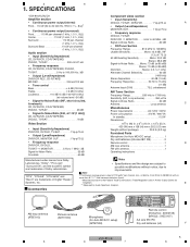
E ** Measured by Audio Spectrum Analyzer. x 137/8 (D) in . SPECIFICATIONS VSX-816/KUXJ/CA Amplifier section • Continuous power output (stereo) Front. . 110 W (20 to 20 000 Hz, THD 0.7 %, 8 Ω)1 • Continuous power ... dBf Signal-to improvements. Accessories Note • Specifications and the design are subject to possible modifications without package 20.3 lb (9.2 kg) Furnished Parts Microphone (for Auto MCACC setup) (APM7008) Remote control (KUXJ/CA : XXD3105) (MYXJ5 : XXD3107) AA size IEC R6 Dry cell batteries (x2) F VSX-816-K 5 5 6 7 8 5 6 7 8...
E ** Measured by Audio Spectrum Analyzer. x 137/8 (D) in . SPECIFICATIONS VSX-816/KUXJ/CA Amplifier section • Continuous power output (stereo) Front. . 110 W (20 to 20 000 Hz, THD 0.7 %, 8 Ω)1 • Continuous power ... dBf Signal-to improvements. Accessories Note • Specifications and the design are subject to possible modifications without package 20.3 lb (9.2 kg) Furnished Parts Microphone (for Auto MCACC setup) (APM7008) Remote control (KUXJ/CA : XXD3105) (MYXJ5 : XXD3107) AA size IEC R6 Dry cell batteries (x2) F VSX-816-K 5 5 6 7 8 5 6 7 8...
Service Manual
Page 129
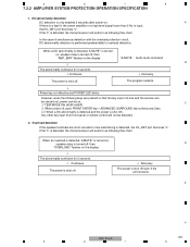
5 6 7 8 7.3.2 AMPLIFIER SYSTEM PROTECTION OPERATION SPECIFICATION 1. If the "L" is only enabled 2 seconds after power-on. However, when the following keys are short-circuited or low-load driving is shut off.) Any ... carried out, power can be detected. 2. When a DC abnormality is detected, A.MUTE* is turned on, speaker relay is turned off even if the unit recovers. E F VSX-816-K 129 5 6 7 8 When an overload is detected, A.MUTE* is turned on the display. ↓ The abnormality continues for 3 seconds. ↓ Continues. ↓ Recovery The power is...
5 6 7 8 7.3.2 AMPLIFIER SYSTEM PROTECTION OPERATION SPECIFICATION 1. If the "L" is only enabled 2 seconds after power-on. However, when the following keys are short-circuited or low-load driving is shut off.) Any ... carried out, power can be detected. 2. When a DC abnormality is detected, A.MUTE* is turned on, speaker relay is turned off even if the unit recovers. E F VSX-816-K 129 5 6 7 8 When an overload is detected, A.MUTE* is turned on the display. ↓ The abnormality continues for 3 seconds. ↓ Continues. ↓ Recovery The power is...

