Service Manual
Page 1
RRV 1 7 7 0 THIS MANUAL IS APPLICABLE TO THE FOLLOWING MODEL(S) AND TYPE(S). Type Model VSX-D906S VSX-07TX VSX-09TX Power Requirement The voltage can be converted by the following method. PCB CONNECTION DIAGRAM 49 5. EXPLODED VIEWS AND PARTS LIST 3 3. PIONEER ELECTRONIC [EUROPE] N.V. KU O AC120V KC O AC120V SD O - SAFETY INFORMATION 2 2. PCB PARTS LIST 80 6. SCHEMATIC DIAGRAM 12 4. GENERAL INFORMATION 96 7.1 PARTS 96 7.1.1 IC 96 7.1.2 DISPLAY 100 7.2 BLOCK DIAGRAM 102 7.3 REMOTE CONTROL UNIT...
RRV 1 7 7 0 THIS MANUAL IS APPLICABLE TO THE FOLLOWING MODEL(S) AND TYPE(S). Type Model VSX-D906S VSX-07TX VSX-09TX Power Requirement The voltage can be converted by the following method. PCB CONNECTION DIAGRAM 49 5. EXPLODED VIEWS AND PARTS LIST 3 3. PIONEER ELECTRONIC [EUROPE] N.V. KU O AC120V KC O AC120V SD O - SAFETY INFORMATION 2 2. PCB PARTS LIST 80 6. SCHEMATIC DIAGRAM 12 4. GENERAL INFORMATION 96 7.1 PARTS 96 7.1.1 IC 96 7.1.2 DISPLAY 100 7.2 BLOCK DIAGRAM 102 7.3 REMOTE CONTROL UNIT...
Service Manual
Page 2
... have the necessary test equipment and tools, and have special safety related characteristics. The use of the customer and service technician. VSX-D906S, VSX-07TX, VSX-09TX 1. If you should not be obtained at a nominal charge from time to perform the repair of the appliance directly into a 120V AC 60 Hz outlet and turn the AC power switch on the parts list in this...
... have the necessary test equipment and tools, and have special safety related characteristics. The use of the customer and service technician. VSX-D906S, VSX-07TX, VSX-09TX 1. If you should not be obtained at a nominal charge from time to perform the repair of the appliance directly into a 120V AC 60 Hz outlet and turn the AC power switch on the parts list in this...
Service Manual
Page 3
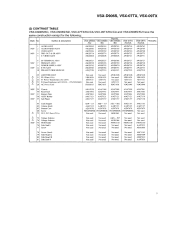
... Not used AHG7046 15 Operating Instructions (French) NSP 16 Caution 220V Not used Not used ARC7158 Not used Not used ARR - 003 Not used Not used Not used Not used Screws adjacent to use parts ofidentical designation. AA) AEX 1007 3 Operating Instructions Sec Contrast table (2) 4 Sub Instruction Manual ISC (English) ARH7022 5 Sub Instruction Manual AC-3 (English) ARH7023 11-13 10 14 NSP NSP 6 Warranty Card 7 AM Loop Antenna 8 Remote Control Unit 9 Front Pad 10 Rear...
... Not used AHG7046 15 Operating Instructions (French) NSP 16 Caution 220V Not used Not used ARC7158 Not used Not used ARR - 003 Not used Not used Not used Not used Screws adjacent to use parts ofidentical designation. AA) AEX 1007 3 Operating Instructions Sec Contrast table (2) 4 Sub Instruction Manual ISC (English) ARH7022 5 Sub Instruction Manual AC-3 (English) ARH7023 11-13 10 14 NSP NSP 6 Warranty Card 7 AM Loop Antenna 8 Remote Control Unit 9 Front Pad 10 Rear...
Service Manual
Page 7
... /SD VSX-07TX /KU/CA VSX-09TX Remarks /KU/CA I AUDIO ASSY NSF 2 AUDIONIDEO ASSY 3 VIDEO ASSY NSF' 4 PRE-OUT & SR ASSY 5 S-VIDEO ASSY AWZ8763 AWZ8766 AWZ8769 AWZ8774 AWZ8808 AWZ8763 AWZ8766 AWZ8769 AWZ8774 AWZ8808 AWZ8763 AWZ8766 AWZ8769 AWZ8774 AWZ8808 AWZ8718 AWZ8719 AWZ8720 AWZ8722 AWZ872 I AWZ8762 AWZ8765 AWZ8768 AWZ8773 AWZ877I NSF' NSP 6 SP TERMINAL ASSY 7 PRIMARY ASSY 9 POWER SUPPLY...
... /SD VSX-07TX /KU/CA VSX-09TX Remarks /KU/CA I AUDIO ASSY NSF 2 AUDIONIDEO ASSY 3 VIDEO ASSY NSF' 4 PRE-OUT & SR ASSY 5 S-VIDEO ASSY AWZ8763 AWZ8766 AWZ8769 AWZ8774 AWZ8808 AWZ8763 AWZ8766 AWZ8769 AWZ8774 AWZ8808 AWZ8763 AWZ8766 AWZ8769 AWZ8774 AWZ8808 AWZ8718 AWZ8719 AWZ8720 AWZ8722 AWZ872 I AWZ8762 AWZ8765 AWZ8768 AWZ8773 AWZ877I NSF' NSP 6 SP TERMINAL ASSY 7 PRIMARY ASSY 9 POWER SUPPLY...
Service Manual
Page 10
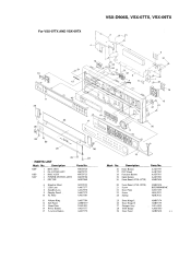
... Volume Ring Center Panel Name Plate Power Button 5-Action Button Parts No. See Contrast table (2) AMB7432 VAM1032 AAD7377 AAD7378 6 Himelon Sheet 7 LED Lens 8 Standby Lens 9 Display Panel 10 FL Filter AED7019 AAK7377 AAK7378 See Contrast table (2) AAK7382 16 Enter Button 17 Regular Button 18 Function Button 19 Input Button 20 Front Panel AAD7379 AAD7380 AAD7381 AAD7382 AMB7433 (2) CONTRAST TABLE 21 Screw BPZ30P080FMC VSX-D906S/KC, VSX-D906S/SD and VSX...
... Volume Ring Center Panel Name Plate Power Button 5-Action Button Parts No. See Contrast table (2) AMB7432 VAM1032 AAD7377 AAD7378 6 Himelon Sheet 7 LED Lens 8 Standby Lens 9 Display Panel 10 FL Filter AED7019 AAK7377 AAK7378 See Contrast table (2) AAK7382 16 Enter Button 17 Regular Button 18 Function Button 19 Input Button 20 Front Panel AAD7379 AAD7380 AAD7381 AAD7382 AMB7433 (2) CONTRAST TABLE 21 Screw BPZ30P080FMC VSX-D906S/KC, VSX-D906S/SD and VSX...
Service Manual
Page 11
... 4 POWER SWITCH ASSY 5 FFC 29P AWZ8724 AWZ8723 AWZ8725 AWZ8784 ADD7060 6 Himelon Sheet 7 LED Lens 8 Standby Lens 9 Display Panel 10 FL Filter AED7019 AAK7377 AAK7378 AAK7379 AAK738 I 11 Volume Ring 12 Sub Panel 13 Name Plate 14 Power Button 15 5-Action Button AAK7384 AMB7437 VAM1032 AAD7377 AAD7378 12 Mark No. 16 17 18 19 20 Description Enter Button PVC Panel Function Button Input Button Front Panel (VSX-07TX) 20 Front Panel (VSX-09TX...
... 4 POWER SWITCH ASSY 5 FFC 29P AWZ8724 AWZ8723 AWZ8725 AWZ8784 ADD7060 6 Himelon Sheet 7 LED Lens 8 Standby Lens 9 Display Panel 10 FL Filter AED7019 AAK7377 AAK7378 AAK7379 AAK738 I 11 Volume Ring 12 Sub Panel 13 Name Plate 14 Power Button 15 5-Action Button AAK7384 AMB7437 VAM1032 AAD7377 AAD7378 12 Mark No. 16 17 18 19 20 Description Enter Button PVC Panel Function Button Input Button Front Panel (VSX-07TX) 20 Front Panel (VSX-09TX...
Service Manual
Page 12
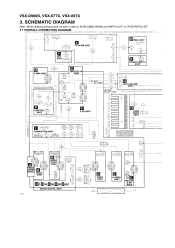
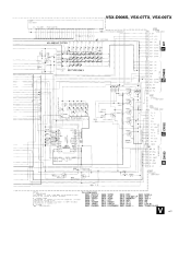
... VIDEO -,-ASSY.a FM/AM A TUNER MODULE AUDIO ASSY L1L PS (111114,M214,[8314,M414) 601 51063 - 1405 5DI 51063-090 4 557 505 969 D VIDEO ASSY S-VIDEO ASSY PRE-OUT & SR ASSY DOLBY DIGITAL ASSY 12 FAN 0167012 J11 ," J35 -' 21 4141 { 215009 , ( 015410),, ,„ .52 i 7, 150 i , 909 , iip I 6-1007 (/) CONNECTION ASSY C,657 0T 4 19 1,42 2 OTA 9 t t (' J 0 ..', ,,-. SCHEMATIC DIAGRAM Note : When ordering service parts...
... VIDEO -,-ASSY.a FM/AM A TUNER MODULE AUDIO ASSY L1L PS (111114,M214,[8314,M414) 601 51063 - 1405 5DI 51063-090 4 557 505 969 D VIDEO ASSY S-VIDEO ASSY PRE-OUT & SR ASSY DOLBY DIGITAL ASSY 12 FAN 0167012 J11 ," J35 -' 21 4141 { 215009 , ( 015410),, ,„ .52 i 7, 150 i , 909 , iip I 6-1007 (/) CONNECTION ASSY C,657 0T 4 19 1,42 2 OTA 9 t t (' J 0 ..', ,,-. SCHEMATIC DIAGRAM Note : When ordering service parts...

Service Manual
Page 13
... AWZ8776 AWZ8716 AWZ8717 AWZ8717 USX-07TX VSX-09TX /KU/CA /KUICA AWZ8716 AWZ8716 AWZ8717 ' AWZ8717 SI PRE-OUT & SR ASSY AWZ8774 AWZ8774 AWZ8722 AWZ8773 12 LIMITER ASSY Not Used AWK7406 AWK7406 AWK7406 VIDEO ASSY in CURR DRIVE ASSY VSX-D9068. I AWX7038 AWX7038 AWX7038' FM/AM TUNER MODULE AX07219 AX01012 AX07219 AX07219 9 II CONNECTION ASSY AWZ8732 AWZ8732 AWZ8732 AWZ8732...
... AWZ8776 AWZ8716 AWZ8717 AWZ8717 USX-07TX VSX-09TX /KU/CA /KUICA AWZ8716 AWZ8716 AWZ8717 ' AWZ8717 SI PRE-OUT & SR ASSY AWZ8774 AWZ8774 AWZ8722 AWZ8773 12 LIMITER ASSY Not Used AWK7406 AWK7406 AWK7406 VIDEO ASSY in CURR DRIVE ASSY VSX-D9068. I AWX7038 AWX7038 AWX7038' FM/AM TUNER MODULE AX07219 AX01012 AX07219 AX07219 9 II CONNECTION ASSY AWZ8732 AWZ8732 AWZ8732 AWZ8732...
Service Manual
Page 47
...TUNER CLASS V 47 Cue, IR f142• '-LE- I 015A. 2 803 -250-2051 FL 2 - SCAN 0=1D KEY IN KEY IN KEY IN 4. HP. PROT O HP. V00 AAV709t VSX-D906S, VSX-07TX, VSX-09TX FL HU_DER 8N41429-8 5 I6 7 8 9 23 2 5212. 48 94A 6855 1K R055 Pre... ASSY 8801 : DVD/TV S802 : LD/SAT S803 : VIDEO S804 : CD S805 : TUNER S806 : TAPE2 S807 : PHONO S808 S809 S810 S811... -W.- 02- L/4051 10 r44 -- 5HE. LED morin 14 DRIVER FAII15 7 11 HP El SP-A 4 14 12 SAS 00...ohm 1/4w ±55 tolerance un oche -wise noted Kr 4ohm. RESET DIRECT LOUDNESS 5815: DRC S822 : BASS+ 5816 : SYS SET...
...TUNER CLASS V 47 Cue, IR f142• '-LE- I 015A. 2 803 -250-2051 FL 2 - SCAN 0=1D KEY IN KEY IN KEY IN 4. HP. PROT O HP. V00 AAV709t VSX-D906S, VSX-07TX, VSX-09TX FL HU_DER 8N41429-8 5 I6 7 8 9 23 2 5212. 48 94A 6855 1K R055 Pre... ASSY 8801 : DVD/TV S802 : LD/SAT S803 : VIDEO S804 : CD S805 : TUNER S806 : TAPE2 S807 : PHONO S808 S809 S810 S811... -W.- 02- L/4051 10 r44 -- 5HE. LED morin 14 DRIVER FAII15 7 11 HP El SP-A 4 14 12 SAS 00...ohm 1/4w ±55 tolerance un oche -wise noted Kr 4ohm. RESET DIRECT LOUDNESS 5815: DRC S822 : BASS+ 5816 : SYS SET...

Service Manual
Page 51
... ASSY - CONNECTION ASSY - E VR ASSY - VOLTAGE AMP ASSY AWK7385 AWZ8717 AWZ8776 AWK7385 AWZ8717 AWZ8776 AWK7364 AWZ8717 AWZ8716 AWK7364 AWZ87I7 AWZ8716 AWK7364 AWZ8717 AWZ8716 DOLBY DIGITAL ASSY FM/AM TUNER MODULE IAMITTER ASSY AWX7038 AXQ7219 Not used AWX7038 AXQ7219 Not used AWX7038 AXQ1012 AWK7406 AWX7038 AXQ7219 AWK7406 AWX7038 AXQ7219 AWK7406 VIDEO ASSY - TRANS TERMINAL ASSY - VSX-13906S, VSX-07TX, VSX-09TX 5. PCB PARTS LIST...
... ASSY - CONNECTION ASSY - E VR ASSY - VOLTAGE AMP ASSY AWK7385 AWZ8717 AWZ8776 AWK7385 AWZ8717 AWZ8776 AWK7364 AWZ8717 AWZ8716 AWK7364 AWZ87I7 AWZ8716 AWK7364 AWZ8717 AWZ8716 DOLBY DIGITAL ASSY FM/AM TUNER MODULE IAMITTER ASSY AWX7038 AXQ7219 Not used AWX7038 AXQ7219 Not used AWX7038 AXQ1012 AWK7406 AWX7038 AXQ7219 AWK7406 AWX7038 AXQ7219 AWK7406 VIDEO ASSY - TRANS TERMINAL ASSY - VSX-13906S, VSX-07TX, VSX-09TX 5. PCB PARTS LIST...

Service Manual
Page 64
....) Frequency (kHz) Level (dBµV/m) Reception Frequency Display I TUNED IND. Adjustment Title FM SC ( lkHz. -±75kHz dev.) Frequency (MHz) Level (dBµV) 1 Center Adjustment 98 Non 80 or more modulation Front End 2 Sensitivity adjustment 98 Low input (0 to FM BAND. • Connect the wiring as shown in Fig. 6-1 . ADJUSTMENT 6.1 TUNER ADJUSTMENT • ADJUSTMENT OF FM TUNER SECTION • Set the FM/AM selector to 30) Stereo 3 Distortion 98 80 TUNED IND. 4 Lighting Level 98...
....) Frequency (kHz) Level (dBµV/m) Reception Frequency Display I TUNED IND. Adjustment Title FM SC ( lkHz. -±75kHz dev.) Frequency (MHz) Level (dBµV) 1 Center Adjustment 98 Non 80 or more modulation Front End 2 Sensitivity adjustment 98 Low input (0 to FM BAND. • Connect the wiring as shown in Fig. 6-1 . ADJUSTMENT 6.1 TUNER ADJUSTMENT • ADJUSTMENT OF FM TUNER SECTION • Set the FM/AM selector to 30) Stereo 3 Distortion 98 80 TUNED IND. 4 Lighting Level 98...

Service Manual
Page 68
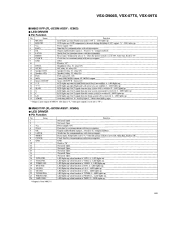
... temperature input. AID input. 34 WATT-IN PA5/AN5 1 Fan wattage input. A/D input. 36 JOG 1/STEREO PA7/AN7 I JOG I : Port data input/TUNER: Stereo input (L: Receiving broadcasting in the main unit from AC3. (L: Request for conununication) 8 RMS PE4/RMC I Remote control input. 9 HPIN PE5 I Reset. 39 EXTAL EXTAL - GND. 42 TX TX 0 Open. 43 TEX TEX I DSP overload detect. H :connect 10 LFE LED PE6/PWM 0 LED lights up during...
... temperature input. AID input. 34 WATT-IN PA5/AN5 1 Fan wattage input. A/D input. 36 JOG 1/STEREO PA7/AN7 I JOG I : Port data input/TUNER: Stereo input (L: Receiving broadcasting in the main unit from AC3. (L: Request for conununication) 8 RMS PE4/RMC I Remote control input. 9 HPIN PE5 I Reset. 39 EXTAL EXTAL - GND. 42 TX TX 0 Open. 43 TEX TEX I DSP overload detect. H :connect 10 LFE LED PE6/PWM 0 LED lights up during...

Service Manual
Page 69
VSX-D906S, VSX-07TX, VSX-09TX No. O Mute for IC. O Clock for sub room. O Tuner mute ON/OFF. O Data for IC. O Segment output 9/KEY scan output 2. O Segment output 12. O Segment output 13. O Timing output 7. O Tinting output 4. O Tuning output 3. Name 51 OSD CK PD5/A50 52 OSD DT PD6/A49 53 OSD CE PD7/A48 54 MRMUTE PF0/A47 55 CE 210 PFI/A46 56 LOUDNESS PF2/A45...
VSX-D906S, VSX-07TX, VSX-09TX No. O Mute for IC. O Clock for sub room. O Tuner mute ON/OFF. O Data for IC. O Segment output 9/KEY scan output 2. O Segment output 12. O Segment output 13. O Timing output 7. O Tinting output 4. O Tuning output 3. Name 51 OSD CK PD5/A50 52 OSD DT PD6/A49 53 OSD CE PD7/A48 54 MRMUTE PF0/A47 55 CE 210 PFI/A46 56 LOUDNESS PF2/A45...
Service Manual
Page 70
..., Data line for communications with microcomputer. L : LEI) lights up . Fixed to "II". Temporarily sets to "L" when the power switch is PHONO. VSX-D906S, VSX-07TX, VSX-09TX • M66311FP (FL-UCOM ASSY : IC803) • LED DRIVER • Pin Function No. "L": LED lights up . LED lights up . L : LED lights up if AC3 signal from the center system is received. Open Not used. LED lights up . * Output is from the rear system (monaural) is...
..., Data line for communications with microcomputer. L : LEI) lights up . Fixed to "II". Temporarily sets to "L" when the power switch is PHONO. VSX-D906S, VSX-07TX, VSX-09TX • M66311FP (FL-UCOM ASSY : IC803) • LED DRIVER • Pin Function No. "L": LED lights up . LED lights up . L : LED lights up if AC3 signal from the center system is received. Open Not used. LED lights up . * Output is from the rear system (monaural) is...
Service Manual
Page 79
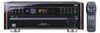
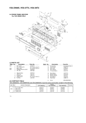
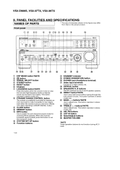
... button Function buttons STANDBY indicator POWER STANDBY/ON button PHONES jack (Headphone terminal) Video input terminals Connect to adjust tone. This button operates in stereo mode only. EC) O • A [ a) t AIIII I - BASS -, + buttons*NOTE Use to raise the low and high frequency levels so that on the actual product. PANEL FACILITIES AND SPECIFICATIONS NAMES OF PARTS * The size of characters shown in DOLBY DIGITAL mode.) O CLASS button MEMORY button MPX button Use to set to a low level. (Works only when operating in the figure may differ from that the sound...
... button Function buttons STANDBY indicator POWER STANDBY/ON button PHONES jack (Headphone terminal) Video input terminals Connect to adjust tone. This button operates in stereo mode only. EC) O • A [ a) t AIIII I - BASS -, + buttons*NOTE Use to raise the low and high frequency levels so that on the actual product. PANEL FACILITIES AND SPECIFICATIONS NAMES OF PARTS * The size of characters shown in DOLBY DIGITAL mode.) O CLASS button MEMORY button MPX button Use to set to a low level. (Works only when operating in the figure may differ from that the sound...
Service Manual
Page 80
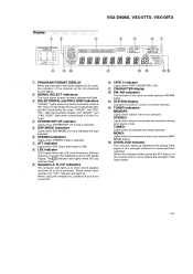
...) lights. 0) STATION display Indicates the station number currently selected. Fel ail 1.O beAM 17111. C) STEREO indicators Lights when STEREO mode is ON. © CHARACTER display • FM, AM indicators The indicator of the channel set for the playback source lights. SYSTEM SET UP DSP MODE JAZZ HALL DANCE THEATER-12 STEREO DIREC1> ON LOUD> ON TONE CONT. VSX-D906S, VSX-07TX, VSX-09TX Display O CD © PROGRAM FC RMAT DISPLAY L C R O O O LS S Rs O O O LFE CD SIGNAL SELECT AC-3 RF DIGITAL ANALOG AUTO SP> ABH.P I TAPE 21 DOLBY > DIGITAL PRO LOGIC...
...) lights. 0) STATION display Indicates the station number currently selected. Fel ail 1.O beAM 17111. C) STEREO indicators Lights when STEREO mode is ON. © CHARACTER display • FM, AM indicators The indicator of the channel set for the playback source lights. SYSTEM SET UP DSP MODE JAZZ HALL DANCE THEATER-12 STEREO DIREC1> ON LOUD> ON TONE CONT. VSX-D906S, VSX-07TX, VSX-09TX Display O CD © PROGRAM FC RMAT DISPLAY L C R O O O LS S Rs O O O LFE CD SIGNAL SELECT AC-3 RF DIGITAL ANALOG AUTO SP> ABH.P I TAPE 21 DOLBY > DIGITAL PRO LOGIC...

Service Manual
Page 81
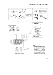
... the AM antenna terminal. AM outdoor antenna 75,p coaxial cable AM indoor antenna (Vinyl-coated wire) 5-6m (15-18 feet) GND LOOP ANTENNA d i AM FM UNBAL 750 GND /77 LOOP ANTENNA AM FM UNBAL 750 • Assembling the AM loop antenna When attaching on the sub woofer. VSX-D906S, VSX-07TX, VSX-09TX CONNECTING DEVICES When connecting or changing equipment, be connected in amplifier*1 L11 0 CD player Cassette deck 2 Cassette deck 1 CD IIIII...
... the AM antenna terminal. AM outdoor antenna 75,p coaxial cable AM indoor antenna (Vinyl-coated wire) 5-6m (15-18 feet) GND LOOP ANTENNA d i AM FM UNBAL 750 GND /77 LOOP ANTENNA AM FM UNBAL 750 • Assembling the AM loop antenna When attaching on the sub woofer. VSX-D906S, VSX-07TX, VSX-09TX CONNECTING DEVICES When connecting or changing equipment, be connected in amplifier*1 L11 0 CD player Cassette deck 2 Cassette deck 1 CD IIIII...
Service Manual
Page 82
..., VSX-07TX, VSX-09TX ■ AM antenna terminal ■ Input/output plugs ■ Speaker terminals rn(3/ 1001 Connect the white plug to L, red plug to R, and yellow plug to insert completely. 10 mm (3/8 in the figures may differ from speakers connected to FR, FL, C, SR, or SL terminals if the SPEAKERS A button on the front panel is set the SPEAKERS B button to the plug's manual for the speaker system. • Sound is output from those on use...
..., VSX-07TX, VSX-09TX ■ AM antenna terminal ■ Input/output plugs ■ Speaker terminals rn(3/ 1001 Connect the white plug to L, red plug to R, and yellow plug to insert completely. 10 mm (3/8 in the figures may differ from speakers connected to FR, FL, C, SR, or SL terminals if the SPEAKERS A button on the front panel is set the SPEAKERS B button to the plug's manual for the speaker system. • Sound is output from those on use...
Service Manual
Page 83
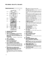
DO : Switches the Dolby Surround mode. SELECT: Use to select the channel for setting the frequency value when the station call is selected or during direct access. O FUNCTION button Switches the function. § MULTI OPERATION button Use to set the multi operation. 03 POWER button Turns ON/OFF the power of the channel selected with the MULTI OPERATION but- O Number/Receiver setting buttons [When setting RECEIVER (operations)] STEREO: Switches the STEREO mode. CH. SELECT: Use to be adjusted. LEVEL-, +: Use to the list input screen when using the Number/Receiver buttons to...
DO : Switches the Dolby Surround mode. SELECT: Use to select the channel for setting the frequency value when the station call is selected or during direct access. O FUNCTION button Switches the function. § MULTI OPERATION button Use to set the multi operation. 03 POWER button Turns ON/OFF the power of the channel selected with the MULTI OPERATION but- O Number/Receiver setting buttons [When setting RECEIVER (operations)] STEREO: Switches the STEREO mode. CH. SELECT: Use to be adjusted. LEVEL-, +: Use to the list input screen when using the Number/Receiver buttons to...
Service Manual
Page 84
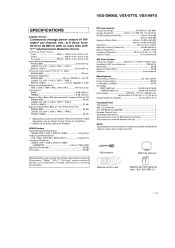
... Antenna 1 AM Loop Antenna 1 Dry Cell Batteries (AA/LR6) 2 Remote Control Unit 1 Operating Instructions 1 Sub instruction manual (Remote Control Unit) 1 Sub instruction manual [System Set up] 1 NOTE: Specifications and the design are trademarks of 100 watts* per channel, min., at 6 ohms, from Dolby Laboratories Licensing Corporation. FM Tuner Section Frequency Range 87.5 MHz to 108 MHz Usable Sensitivity Mono: 11.2 dBf, IHF (1.0 pV/75 0) 50 dB Quieting Sensitivity Mono: 16.8 dBf Stereo: 38.6 dBf Signal...
... Antenna 1 AM Loop Antenna 1 Dry Cell Batteries (AA/LR6) 2 Remote Control Unit 1 Operating Instructions 1 Sub instruction manual (Remote Control Unit) 1 Sub instruction manual [System Set up] 1 NOTE: Specifications and the design are trademarks of 100 watts* per channel, min., at 6 ohms, from Dolby Laboratories Licensing Corporation. FM Tuner Section Frequency Range 87.5 MHz to 108 MHz Usable Sensitivity Mono: 11.2 dBf, IHF (1.0 pV/75 0) 50 dB Quieting Sensitivity Mono: 16.8 dBf Stereo: 38.6 dBf Signal...


