Owner's Manual
Page 12
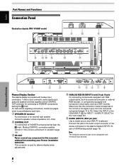
...] in parentheses by each item. 1 SPEAKER (R) terminal For connection of an external right speaker. Select this unit as a DVD recorder. English Part Names and Functions Connection Panel Illustration depicts PRO-1010HD model. Connect a speaker whose impedance is not compatible with a ...the format of the device connected to PIONEER components bearing the Î mark. S-VIDEO INPUT3 VIDEO INPUT4 INPUT 3/4 AUDIO ANALOG RGB INPUT5 AUDIO = IN OUT R L G(ON SYNC) B R HD (H/V SYNC) VD ~! @ # R L $ Part Names and Functions R SPEAKER 8+Ω ~16Ω- 1 OUT ...
...] in parentheses by each item. 1 SPEAKER (R) terminal For connection of an external right speaker. Select this unit as a DVD recorder. English Part Names and Functions Connection Panel Illustration depicts PRO-1010HD model. Connect a speaker whose impedance is not compatible with a ...the format of the device connected to PIONEER components bearing the Î mark. S-VIDEO INPUT3 VIDEO INPUT4 INPUT 3/4 AUDIO ANALOG RGB INPUT5 AUDIO = IN OUT R L G(ON SYNC) B R HD (H/V SYNC) VD ~! @ # R L $ Part Names and Functions R SPEAKER 8+Ω ~16Ω- 1 OUT ...

Owner's Manual
Page 13
... display; Connect these jacks to the audio output connectors of components connected to obtain sound when INPUT2 (analog audio) is selected. Connect a speaker that has an impedance of 8 -16 Ω. = S-VIDEO (INPUT3) (S-video jack) For connection of components that have an S-video...jack such as a video deck, video camera, laser disc player, or DVD recorder (page 16). ! SPEAKER (L) terminal For connection of this connector, and the other component. Note The left speaker. 6 HDMI (INPUT1) (HDMI jack) For connection of components that have a digital video output terminal ...
... display; Connect these jacks to the audio output connectors of components connected to obtain sound when INPUT2 (analog audio) is selected. Connect a speaker that has an impedance of 8 -16 Ω. = S-VIDEO (INPUT3) (S-video jack) For connection of components that have an S-video...jack such as a video deck, video camera, laser disc player, or DVD recorder (page 16). ! SPEAKER (L) terminal For connection of this connector, and the other component. Note The left speaker. 6 HDMI (INPUT1) (HDMI jack) For connection of components that have a digital video output terminal ...

Owner's Manual
Page 22
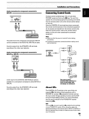
... to secure the wire in place. This will result in their terminals. Installation and Connections 18 EN Sound is output from the SPEAKER (L/R) terminals according to malfunction or stop. Audio connection for component connected to INPUT2 AUDIO INPUT2 R L The audio line for INPUT3...(D-sub or HDMI) IINNPPUUTT11 AUDIO R L The audio line for INPUT1 D-sub and HDMI. *2 The audio input jack is output from the SPEAKER (L/R) terminals according to protrude excessively, since they may touch each other, causing a short circuit. Note When using AUDIO INPUT2, set AUDIO to ...
... to secure the wire in place. This will result in their terminals. Installation and Connections 18 EN Sound is output from the SPEAKER (L/R) terminals according to malfunction or stop. Audio connection for component connected to INPUT2 AUDIO INPUT2 R L The audio line for INPUT3...(D-sub or HDMI) IINNPPUUTT11 AUDIO R L The audio line for INPUT1 D-sub and HDMI. *2 The audio input jack is output from the SPEAKER (L/R) terminals according to protrude excessively, since they may touch each other, causing a short circuit. Note When using AUDIO INPUT2, set AUDIO to ...
Owner's Manual
Page 23
Sound is output from the SPEAKER (L/R) terminals according to INPUT3 or INPUT4 INPUT 3/4 AUDIO R L Installation and Connections Connecting Control Cords Connect control cords between this unit and other PIONEER equipment having the Î logo. Note If you use SR+, be connected to the AUDIO R/L (INPUT5...(commercially available) are mono sound cables with a PIONEER AV receiver. About SR+ The CONTROL OUT terminal on the rear of this unit (because this unit does not feature a built-in tuner, there is output from the SPEAKER (L/R) terminals according to either INPUT3 or INPUT4....
Sound is output from the SPEAKER (L/R) terminals according to INPUT3 or INPUT4 INPUT 3/4 AUDIO R L Installation and Connections Connecting Control Cords Connect control cords between this unit and other PIONEER equipment having the Î logo. Note If you use SR+, be connected to the AUDIO R/L (INPUT5...(commercially available) are mono sound cables with a PIONEER AV receiver. About SR+ The CONTROL OUT terminal on the rear of this unit (because this unit does not feature a built-in tuner, there is output from the SPEAKER (L/R) terminals according to either INPUT3 or INPUT4....

Owner's Manual
Page 34
... restore the sound. INPUT1 STANDARD VOLUME : 11 Muting the Sound AXD1496 MUTING Press the MUTING button on the screen can be slightly different from the speakers. Display operating panel Remote control unit Press the DISPLAY button. Press the MUTING button again to respectively decrease and increase the volume of the manufacturer...
... restore the sound. INPUT1 STANDARD VOLUME : 11 Muting the Sound AXD1496 MUTING Press the MUTING button on the screen can be slightly different from the speakers. Display operating panel Remote control unit Press the DISPLAY button. Press the MUTING button again to respectively decrease and increase the volume of the manufacturer...
Owner's Manual
Page 55
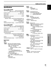
Weight 39 kg (86 lbs.) Operating temperature range ....... 0 to 40 °C (32 to 104°F) General (PRO-810HD) Light emission panel 43-inch AC Plasma Panel 95.2 (W) x 53.6 (H) x 109.3 (diagonal) cm Number of pixels 1280 x 768 Power supply AC ...; AUDIO INPUT (for INPUT3/4) Pin jack (x2) L/R ... 500mVrms/more than 10 kΩ AUDIO INPUT (for INPUT5) Pin jack (x2) L/R ... 500mVrms/more than 10 kΩ Output SPEAKER L/R ... 8 - 16 Ω/7 W +7 W (at 8 Ω) Control RS-232C ... TTL level /positive and negative polarity /2.2 kΩ G ON SYNC ... 1 Vp-p/75 Ω/negative ...
Weight 39 kg (86 lbs.) Operating temperature range ....... 0 to 40 °C (32 to 104°F) General (PRO-810HD) Light emission panel 43-inch AC Plasma Panel 95.2 (W) x 53.6 (H) x 109.3 (diagonal) cm Number of pixels 1280 x 768 Power supply AC ...; AUDIO INPUT (for INPUT3/4) Pin jack (x2) L/R ... 500mVrms/more than 10 kΩ AUDIO INPUT (for INPUT5) Pin jack (x2) L/R ... 500mVrms/more than 10 kΩ Output SPEAKER L/R ... 8 - 16 Ω/7 W +7 W (at 8 Ω) Control RS-232C ... TTL level /positive and negative polarity /2.2 kΩ G ON SYNC ... 1 Vp-p/75 Ω/negative ...


