
Owner's Manual
Page 5
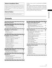
... Accessories 3 Part Names and Functions 4 Main Unit 4 Remote Control Unit 5 Connection Panel 6 Installation and Connections 8 Installation of Terms 42 1 PRO-1000HDI / PRO-800HDI Keep this manual to the customer and explain to the customer how to handle the product. Always have an installation specialist or your Plasma Display, please carefully read ... the Unit 8 About the Input Connectors on Installation Work: This product is installed by mistake in installation or mounting, misuse, modification or a natural disaster. PIONEER cannot assume liabilities for purchasing this...
... Accessories 3 Part Names and Functions 4 Main Unit 4 Remote Control Unit 5 Connection Panel 6 Installation and Connections 8 Installation of Terms 42 1 PRO-1000HDI / PRO-800HDI Keep this manual to the customer and explain to the customer how to handle the product. Always have an installation specialist or your Plasma Display, please carefully read ... the Unit 8 About the Input Connectors on Installation Work: This product is installed by mistake in installation or mounting, misuse, modification or a natural disaster. PIONEER cannot assume liabilities for purchasing this...
Owner's Manual
Page 6
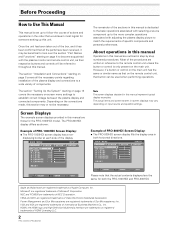
... page 4 to become acquainted with adjusting the plasma display picture to a wide variety of the procedures are outlined in this manual represent typical display examples. The PRO-800HDI display differs as their respective buttons and controls will be necessary. L E V E L B. L E V E ...: +60 :0 :0 SET UP INPUT1 OPTION RE S ET SELECT SET ENTER MENU EXIT Example of PRO-800HDI Screen Display: ÷ The PRO-800HDI screen display fills the display area in this manual is dedicated to the basic operations associated with selecting a source component up to the more complex operations...
... page 4 to become acquainted with adjusting the plasma display picture to a wide variety of the procedures are outlined in this manual represent typical display examples. The PRO-800HDI display differs as their respective buttons and controls will be necessary. L E V E L B. L E V E ...: +60 :0 :0 SET UP INPUT1 OPTION RE S ET SELECT SET ENTER MENU EXIT Example of PRO-800HDI Screen Display: ÷ The PRO-800HDI screen display fills the display area in this manual is dedicated to the basic operations associated with selecting a source component up to the more complex operations...
Owner's Manual
Page 7
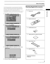
... control unit 3 AA (R6) batteries (x 2) SELECT SET ENTER MENU EXIT 3 Press 5/∞ to select the item to adjust the value. ÷ Operating Instructions ÷ Warranty 3 PRO-1000HDI / PRO-800HDI R. L EVEL H. POS I T I ON : 0 ADJUST MENU SET EXIT SET 5 Press 5/∞/2/3 to be adjusted. MAIN MENU PICTURE SCREEN POS I T I ON : CL OCK / PHASE ... is proceeding as it should. MAIN MENU PICTURE SCREEN CONT RAST BR I ON : 0 V. E NHANCE V. POS I T I GHT . L EVEL G. Please familiarize yourself with this manual. 1 Press MENU to display the menu screen.
... control unit 3 AA (R6) batteries (x 2) SELECT SET ENTER MENU EXIT 3 Press 5/∞ to select the item to adjust the value. ÷ Operating Instructions ÷ Warranty 3 PRO-1000HDI / PRO-800HDI R. L EVEL H. POS I T I ON : 0 ADJUST MENU SET EXIT SET 5 Press 5/∞/2/3 to be adjusted. MAIN MENU PICTURE SCREEN POS I T I ON : CL OCK / PHASE ... is proceeding as it should. MAIN MENU PICTURE SCREEN CONT RAST BR I ON : 0 V. E NHANCE V. POS I T I GHT . L EVEL G. Please familiarize yourself with this manual. 1 Press MENU to display the menu screen.
Owner's Manual
Page 12
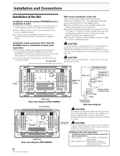
... that can be careful of deterioration and dirt build up on edge. PIONEER will not be inserted 1/2 inch (12 mm) to 11/16 inch (18 mm) into the main unit from the attaching surface for securing the unit. 8 PRO-1000HDI / PRO-800HDI As a result, two or more locations above and below . ÷..., please be sure to use the bolts provided with the stand or installation bracket. ÷ For details concerning installation, please refer to the instruction manual provided with bolt holes for accident or damage caused by the use an M8 (Pitch = 1.25 mm) bolt. (Only this size bolt can...
... that can be careful of deterioration and dirt build up on edge. PIONEER will not be inserted 1/2 inch (12 mm) to 11/16 inch (18 mm) into the main unit from the attaching surface for securing the unit. 8 PRO-1000HDI / PRO-800HDI As a result, two or more locations above and below . ÷..., please be sure to use the bolts provided with the stand or installation bracket. ÷ For details concerning installation, please refer to the instruction manual provided with bolt holes for accident or damage caused by the use an M8 (Pitch = 1.25 mm) bolt. (Only this size bolt can...
Owner's Manual
Page 15
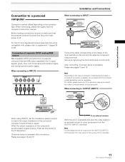
...40). For details, please read the computer's instruction manual. Connection of separate SYNC analog RGB source Make separate SYNC connections for a personal computer that the personal computer's power and this unit is off or in standby. 11 PRO-1000HDI / PRO-800HDI When connecting to INPUT2 (ON SYNC) G B ...: green, blue, red, horizontal synchronization signal, and vertical synchronization signal. When connecting, please thoroughly read your PC's instruction manual or consult the maker or nearest dealer of your computer. Please see pages 18 and 19. When the output impedance of the...
...40). For details, please read the computer's instruction manual. Connection of separate SYNC analog RGB source Make separate SYNC connections for a personal computer that the personal computer's power and this unit is off or in standby. 11 PRO-1000HDI / PRO-800HDI When connecting to INPUT2 (ON SYNC) G B ...: green, blue, red, horizontal synchronization signal, and vertical synchronization signal. When connecting, please thoroughly read your PC's instruction manual or consult the maker or nearest dealer of your computer. Please see pages 18 and 19. When the output impedance of the...

Owner's Manual
Page 18
.... Installation and Connections About DTV Set Top Box Connection To ensure proper connection, please carefully read the instruction manual supplied with the DTV set top box output signals that the audio component's power and the unit's main power is output from the • SPEAKER terminals • Stereo mini jack (L/R). 14 PRO-1000HDI / PRO-800HDI
.... Installation and Connections About DTV Set Top Box Connection To ensure proper connection, please carefully read the instruction manual supplied with the DTV set top box output signals that the audio component's power and the unit's main power is output from the • SPEAKER terminals • Stereo mini jack (L/R). 14 PRO-1000HDI / PRO-800HDI
Owner's Manual
Page 23
..., analog RGB signals may result in the screen image appearing with the component you are using this setup, be sure to the instruction manual supplied with a whitish or greenish cast. Setup of connections made. L EVEL G. MAIN MENU INPUT1 PICTURE SCREEN SET UP OPTION I ... the component that you are appropriate and available for each time SET is pressed. RGB COMPONENT The table below shows what settings are connecting. 19 PRO-1000HDI / PRO-800HDI The menu screen appears. R. ENHANCE :0 :0 : +60 : +60 : +60 :0 :0 SET UP INPUT1 OPTION RE S ET SELECT SET ENTER MENU ...
..., analog RGB signals may result in the screen image appearing with the component you are using this setup, be sure to the instruction manual supplied with a whitish or greenish cast. Setup of connections made. L EVEL G. MAIN MENU INPUT1 PICTURE SCREEN SET UP OPTION I ... the component that you are appropriate and available for each time SET is pressed. RGB COMPONENT The table below shows what settings are connecting. 19 PRO-1000HDI / PRO-800HDI The menu screen appears. R. ENHANCE :0 :0 : +60 : +60 : +60 :0 :0 SET UP INPUT1 OPTION RE S ET SELECT SET ENTER MENU ...

Owner's Manual
Page 24
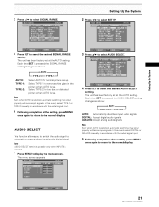
... RA NGE : AU T O AUD I O SEL ECT : AUT O 20 PRO-1000HDI / PRO-800HDI SELECT SET ENTER MENU EXIT Accepts Y PB/CB PR/CR (4 : 2 : 2) signals. SIGNAL RANGE This function allows you to switch the input signal format to automatic or manual when inputting the digital signal. Follow the procedure described below and make... when INPUT5 is selected. 1 Press MENU to display the menu screen. In this event, select COLOR-1, COLOR-2 or COLOR-3 manually in accordance with someinput signals. Each time SET is necessary. Note SIGNAL RANGE setting is possible only when INPUT5 is selected. 1...
... RA NGE : AU T O AUD I O SEL ECT : AUT O 20 PRO-1000HDI / PRO-800HDI SELECT SET ENTER MENU EXIT Accepts Y PB/CB PR/CR (4 : 2 : 2) signals. SIGNAL RANGE This function allows you to switch the input signal format to automatic or manual when inputting the digital signal. Follow the procedure described below and make... when INPUT5 is selected. 1 Press MENU to display the menu screen. In this event, select COLOR-1, COLOR-2 or COLOR-3 manually in accordance with someinput signals. Each time SET is necessary. Note SIGNAL RANGE setting is possible only when INPUT5 is selected. 1...
Owner's Manual
Page 25
... : AU T O S I GNAL RA NGE : AU T O AUD I O SEL ECT : AUT O SELECT SET CHANGE MENU EXIT 4 Press SET to automatic or manual when inputting the digital signal. SELECT SET ENTER MENU EXIT 21 PRO-1000HDI / PRO-800HDI Setting Up the System 3 Press 5/∞ to select AUDIO SELECT. Select TYPE-2 for normal picture set up. CO LOR...
... : AU T O S I GNAL RA NGE : AU T O AUD I O SEL ECT : AUT O SELECT SET CHANGE MENU EXIT 4 Press SET to automatic or manual when inputting the digital signal. SELECT SET ENTER MENU EXIT 21 PRO-1000HDI / PRO-800HDI Setting Up the System 3 Press 5/∞ to select AUDIO SELECT. Select TYPE-2 for normal picture set up. CO LOR...

Owner's Manual
Page 32
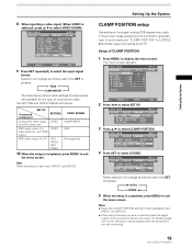
...: CL OCK / PHASE : SET UP 0/ 0 0/ 0 RE S ET INPUT1 OPTION SELECT SET ENTER MENU EXIT 28 PRO-1000HDI / PRO-800HDI MAIN MENU PICTURE SCREEN POS I T I GHT . Manual Adjustment of signals. luminance and certain other kinds of Screen Position and Clock Note Make these adjustments for each signal type. In...on either the main unit operating panel or remote control unit. ÷ Optimum settings may not be set in the following section "Manual Adjustment of the options that can be possible for low- R. Notes ÷ This adjustment is supported only when a computer signal is...
...: CL OCK / PHASE : SET UP 0/ 0 0/ 0 RE S ET INPUT1 OPTION SELECT SET ENTER MENU EXIT 28 PRO-1000HDI / PRO-800HDI MAIN MENU PICTURE SCREEN POS I T I GHT . Manual Adjustment of signals. luminance and certain other kinds of Screen Position and Clock Note Make these adjustments for each signal type. In...on either the main unit operating panel or remote control unit. ÷ Optimum settings may not be set in the following section "Manual Adjustment of the options that can be possible for low- R. Notes ÷ This adjustment is supported only when a computer signal is...


