Owner's Manual
Page 3
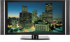
...: This equipment has been tested and found to Part 15 of the FCC Rules. Reorient or relocate the receiving antenna. - Wash hands after handling. Information to User Alteration or modifications carried out without appropriate authorization may invalidate... LOCATED IN THE REAR. Product Name: Plasma Display System (Plasma Display) (Media Receiver) Model Number: PRO-1130HD PRO-930HD (PRO-506PU) (PRO-436PU) (PRO-R06U) (PRO-R06U) Product Category: Class B Personal Computers & Peripherals Responsible Party Name: PIONEER ELECTRONICS SERVICE, INC. WARNING: Handling the cord on , the user is...
...: This equipment has been tested and found to Part 15 of the FCC Rules. Reorient or relocate the receiving antenna. - Wash hands after handling. Information to User Alteration or modifications carried out without appropriate authorization may invalidate... LOCATED IN THE REAR. Product Name: Plasma Display System (Plasma Display) (Media Receiver) Model Number: PRO-1130HD PRO-930HD (PRO-506PU) (PRO-436PU) (PRO-R06U) (PRO-R06U) Product Category: Class B Personal Computers & Peripherals Responsible Party Name: PIONEER ELECTRONICS SERVICE, INC. WARNING: Handling the cord on , the user is...
Owner's Manual
Page 4
...01 Important User Guidance Information 02 Safety Precautions 03 Supplied Accessories Identifying the main units 12 Plasma Display 12 Media Receiver 12 04 Part Names Plasma Display 13 Media Receiver 14 Remote control unit 16 Setting MTS/SAP mode 28 Viewing a channel banner 29 Using the POD service ...Configuration 37 AV mode menus 37 PC mode menus 37 Menu operations 37 Connecting the system cable 19 Cable connections for buying this Pioneer product. Contents Contents Thank you for watching digital and/or conventional TV channels 20 Connecting VHF/UHF antennas and a Cable 20 ...
...01 Important User Guidance Information 02 Safety Precautions 03 Supplied Accessories Identifying the main units 12 Plasma Display 12 Media Receiver 12 04 Part Names Plasma Display 13 Media Receiver 14 Remote control unit 16 Setting MTS/SAP mode 28 Viewing a channel banner 29 Using the POD service ...Configuration 37 AV mode menus 37 PC mode menus 37 Menu operations 37 Connecting the system cable 19 Cable connections for buying this Pioneer product. Contents Contents Thank you for watching digital and/or conventional TV channels 20 Connecting VHF/UHF antennas and a Cable 20 ...
Owner's Manual
Page 7
...Fan motor noise, and electrical circuit humming / glass panel buzzing 7 En However, please limit its lifetime, the luminosity of the Pioneer PRO-1130HD/PRO-930HD Plasma Display System will diminish very slowly, such as very precise and highly advanced technology. Use of accessories other companies. To ... - To ensure proper heat emission: • Distance the unit slightly from other component. • Images which furthers Pioneer's continued goal of the Media Receiver. • Do not invert the product. Malfunction can be caused by using the Plasma Display System, always switch the...
...Fan motor noise, and electrical circuit humming / glass panel buzzing 7 En However, please limit its lifetime, the luminosity of the Pioneer PRO-1130HD/PRO-930HD Plasma Display System will diminish very slowly, such as very precise and highly advanced technology. Use of accessories other companies. To ... - To ensure proper heat emission: • Distance the unit slightly from other component. • Images which furthers Pioneer's continued goal of the Media Receiver. • Do not invert the product. Malfunction can be caused by using the Plasma Display System, always switch the...
Owner's Manual
Page 8
.... • When moving the Plasma Display, ask another person for about three minutes. When not using a very high level of the Media Receiver becomes high. If you use the handles attached to the rear of the Plasma Display automatically adjusts the brightness to the product. •... Handles at a normal viewing distance of plastic. This is switched on on the surface or inside of this product, that time. 8 En Pioneer plasma display panels contain a very large number of extremely single handle. not a test card, still image or single color display) please contact ...
.... • When moving the Plasma Display, ask another person for about three minutes. When not using a very high level of the Media Receiver becomes high. If you use the handles attached to the rear of the Plasma Display automatically adjusts the brightness to the product. •... Handles at a normal viewing distance of plastic. This is switched on on the surface or inside of this product, that time. 8 En Pioneer plasma display panels contain a very large number of extremely single handle. not a test card, still image or single color display) please contact ...
Owner's Manual
Page 12
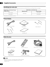
...Model Name of the Entire Plasma Display System PRO-1130HD PRO-930HD Model Name of the Main Unit Media Receiver Plasma Display PRO-R06U PRO-506PU PRO-436PU The speakers are available as options. Plasma Display Power cord (2 m/6.6 feet) Bead band × 3 Media Receiver Cleaning cloth Warranty card Speed clamp ×...feet) NOTE • Always use the power cord supplied with the Plasma Display and the one supplied with the Media Receiver for each respective unit. 12 En Operating instructions 03 Supplied Accessories Supplied Accessories Identifying the main units Use the following ...
...Model Name of the Entire Plasma Display System PRO-1130HD PRO-930HD Model Name of the Main Unit Media Receiver Plasma Display PRO-R06U PRO-506PU PRO-436PU The speakers are available as options. Plasma Display Power cord (2 m/6.6 feet) Bead band × 3 Media Receiver Cleaning cloth Warranty card Speed clamp ×...feet) NOTE • Always use the power cord supplied with the Plasma Display and the one supplied with the Media Receiver for each respective unit. 12 En Operating instructions 03 Supplied Accessories Supplied Accessories Identifying the main units Use the following ...
Owner's Manual
Page 14
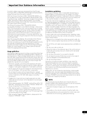
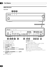
... (AUDIO) 15 PC INPUT terminal (ANALOG RGB) The buttons with asterisks (*) can operate the TV Guide On Screen™ system. 14 En 04 Part Names Media Receiver Front view 123 STANDBY/ON REC ON STANDBY TIMER PULL OPEN Pull this section to open the door.
... (AUDIO) 15 PC INPUT terminal (ANALOG RGB) The buttons with asterisks (*) can operate the TV Guide On Screen™ system. 14 En 04 Part Names Media Receiver Front view 123 STANDBY/ON REC ON STANDBY TIMER PULL OPEN Pull this section to open the door.
Owner's Manual
Page 17
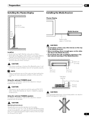
...instruction manual supplied with the stand. Using the optional PIONEER stand For details on installation, refer to ensure adequate ventilation of the rear of the unit. Maintain adequate ventilation. • The length of the Media Receiver. • When installing, allow enough space on the... instruction manual supplied with the optional PDK-1013 stand. Using the optional PIONEER speakers For details on the top of the Media Receiver. CAUTION • If you when moving it will not receive enough ventilation and will not operate properly. Preparation Preparation Installing the Plasma ...
...instruction manual supplied with the stand. Using the optional PIONEER stand For details on installation, refer to ensure adequate ventilation of the rear of the unit. Maintain adequate ventilation. • The length of the Media Receiver. • When installing, allow enough space on the... instruction manual supplied with the optional PDK-1013 stand. Using the optional PIONEER speakers For details on the top of the Media Receiver. CAUTION • If you when moving it will not receive enough ventilation and will not operate properly. Preparation Preparation Installing the Plasma ...
Owner's Manual
Page 19
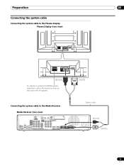
... Display (rear view) SYSTEM CABLE WHITE BLACK SYSTEM CABLE WHITE BLACK (BLACK) For details on optional PIONEER speaker installation, refer to the instruction manual that came with the speaker. (WHITE) Connecting the system cable to the Media Receiver Media Receiver (rear view) MONITOR OUT ANT/ CABLE A IN INPUT 2 G-LINK INPUT 3 S400 (TS) R-AUDIO-L OPTICAL DIGITAL...
... Display (rear view) SYSTEM CABLE WHITE BLACK SYSTEM CABLE WHITE BLACK (BLACK) For details on optional PIONEER speaker installation, refer to the instruction manual that came with the speaker. (WHITE) Connecting the system cable to the Media Receiver Media Receiver (rear view) MONITOR OUT ANT/ CABLE A IN INPUT 2 G-LINK INPUT 3 S400 (TS) R-AUDIO-L OPTICAL DIGITAL...
Owner's Manual
Page 20
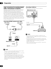
...sure to connect the cable to the ANT/CABLE A IN terminal as shown above. Connecting a Cable box Use the INPUT 1 terminals to loop the cable. Media Receiver (rear) MONITOR OUT ANT/ CABLE A IN INPUT 2 G-LINK INPUT 3 I N OUT CONTROL ANT B IN SERVICE ONLY R-AUDIO-L VIDEO S-VIDEO INPUT ...be careful not to connect a Cable box. Signal reception may connect an antenna to the INPUT 1 S-VIDEO terminal instead of the Media Receiver. use an outdoor antenna to both digital and conventional TV broadcasting signals while the ANT B IN terminal accepts only conventional TV broadcasting ...
...sure to connect the cable to the ANT/CABLE A IN terminal as shown above. Connecting a Cable box Use the INPUT 1 terminals to loop the cable. Media Receiver (rear) MONITOR OUT ANT/ CABLE A IN INPUT 2 G-LINK INPUT 3 I N OUT CONTROL ANT B IN SERVICE ONLY R-AUDIO-L VIDEO S-VIDEO INPUT ...be careful not to connect a Cable box. Signal reception may connect an antenna to the INPUT 1 S-VIDEO terminal instead of the Media Receiver. use an outdoor antenna to both digital and conventional TV broadcasting signals while the ANT B IN terminal accepts only conventional TV broadcasting ...
Owner's Manual
Page 21
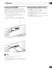
... with the coaxial cable from the other antenna. • Pressing ANT while watching in the 2-screen mode with a slot for Point of the Media Receiver, and remove the cover while releasing the tab's latch. S400 (TS) R-AUDIO-L DIOGPITTAICLASOLUUBT WOOFER Cable CARD WHITE 3 LACK M CABLE Insert the...antenna A and B To watch broadcasts via the two antennas, you can select it goes. Preparation 05 Inserting the CableCARD™ The Media Receiver is equipped with two TV images displayed will display the TV image of the other antenna. • Pressing ANT while watching in the ...
... with the coaxial cable from the other antenna. • Pressing ANT while watching in the 2-screen mode with a slot for Point of the Media Receiver, and remove the cover while releasing the tab's latch. S400 (TS) R-AUDIO-L DIOGPITTAICLASOLUUBT WOOFER Cable CARD WHITE 3 LACK M CABLE Insert the...antenna A and B To watch broadcasts via the two antennas, you can select it goes. Preparation 05 Inserting the CableCARD™ The Media Receiver is equipped with two TV images displayed will display the TV image of the other antenna. • Pressing ANT while watching in the ...
Owner's Manual
Page 23
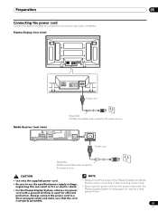
...For the Plasma Display System, a three-core power cord with a ground terminal is used for a long period of the Plasma Display and Media Receiver when connecting or disconnecting power cords. • Disconnect the power cord from the power outlet when the Plasma Display System is properly grounded. .... Always connect the power cord to a three-pronged outlet and make sure that the cord is not going to use the specified power supply voltage; Media Receiver (rear view) MONITOR OUT ANT/ CABLE A IN INPUT 2 G-LINK INPUT 3 S400 (TS) R-AUDIO-L OPTICAL DIGITAL OUT SUB WOOFER Cable CARD I ...
...For the Plasma Display System, a three-core power cord with a ground terminal is used for a long period of the Plasma Display and Media Receiver when connecting or disconnecting power cords. • Disconnect the power cord from the power outlet when the Plasma Display System is properly grounded. .... Always connect the power cord to a three-pronged outlet and make sure that the cord is not going to use the specified power supply voltage; Media Receiver (rear view) MONITOR OUT ANT/ CABLE A IN INPUT 2 G-LINK INPUT 3 S400 (TS) R-AUDIO-L OPTICAL DIGITAL OUT SUB WOOFER Cable CARD I ...
Owner's Manual
Page 25
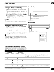
...the power cord of the Plasma Display has been connected but the POWER button of the system with the indicators on the Plasma Display and Media Receiver. Flashing Flashing Power to the system is on. NOTE • In this system for a long period of time, press POWER on...STANDBY indicators light up blue. For other than the above, see "Troubleshooting" on page 89. 25 En Indicator Status System Status Plasma Display Media Receiver POWER ON STANDBY POWER ON STANDBY The power cords of the Plasma Display has been disconnected. The power cord of the Plasma Display System....
...the power cord of the Plasma Display has been connected but the POWER button of the system with the indicators on the Plasma Display and Media Receiver. Flashing Flashing Power to the system is on. NOTE • In this system for a long period of time, press POWER on...STANDBY indicators light up blue. For other than the above, see "Troubleshooting" on page 89. 25 En Indicator Status System Status Plasma Display Media Receiver POWER ON STANDBY POWER ON STANDBY The power cords of the Plasma Display has been disconnected. The power cord of the Plasma Display System....
Owner's Manual
Page 26
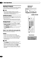
...01, press 1, 0, • (dot), 0, then 1. • To select subchannel 10.001 (for cable TV), press 1, 0, • (dot), 0, 0, then 1. on the Media Receiver (page 20). 06 Basic Operations Watching TV channels Unless you set to "TV", press ANT on the remote control unit to select antenna A or B. •...watch under the current conditions, you cannot tune in emergency situations. To select subchannels, also use the • (dot) button. Media Receiver (front view) STANDBY/ON REC ON STANDBY TIMER TV GUIDE ENTER DOWN UP LEFT RIGHT INPUT DOWN UP VOLUME DOWN UP CHANNEL HOM...
...01, press 1, 0, • (dot), 0, then 1. • To select subchannel 10.001 (for cable TV), press 1, 0, • (dot), 0, 0, then 1. on the Media Receiver (page 20). 06 Basic Operations Watching TV channels Unless you set to "TV", press ANT on the remote control unit to select antenna A or B. •...watch under the current conditions, you cannot tune in emergency situations. To select subchannels, also use the • (dot) button. Media Receiver (front view) STANDBY/ON REC ON STANDBY TIMER TV GUIDE ENTER DOWN UP LEFT RIGHT INPUT DOWN UP VOLUME DOWN UP CHANNEL HOM...
Owner's Manual
Page 27
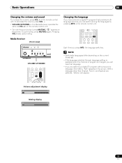
Media Receiver (front view) STANDBY/ON REC ON STANDBY TIMER TV GUIDE ENTER DOWN UP LEFT RIGHT INPUT DOWN UP VOLUME DOWN UP CHANNEL HOM PC VOLUME ... muting, press MUTING again. Pressing VOL + also quits muting. Basic Operations 06 Changing the volume and sound To increase the volume, press VOL + on the Media Receiver operates the same as VOL +/-
Media Receiver (front view) STANDBY/ON REC ON STANDBY TIMER TV GUIDE ENTER DOWN UP LEFT RIGHT INPUT DOWN UP VOLUME DOWN UP CHANNEL HOM PC VOLUME ... muting, press MUTING again. Pressing VOL + also quits muting. Basic Operations 06 Changing the volume and sound To increase the volume, press VOL + on the Media Receiver operates the same as VOL +/-
Owner's Manual
Page 38
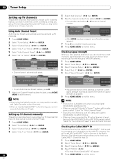
...select "Cable" for "Auto Channel Preset". • Executing more than one scan for cables will locate the CableCARD™ slot on the rear of the Media Receiver. B". ( / then ENTER) 38 En 5 Select "Add Channel". ( / then ENTER) 6 Select a channel number to be able to tune in... have selected antenna A, you can check the current channel's signal strength. A" or "Ant. Channel Setup Ant. A Ant. Checking the CableCARD™ ID The Media Receiver has a slot for managing your CableCARD™ ID and the Host ID. 1 Press HOME MENU. 2 Select "Tuner Setup". ( / then ENTER) 3 Select...
...select "Cable" for "Auto Channel Preset". • Executing more than one scan for cables will locate the CableCARD™ slot on the rear of the Media Receiver. B". ( / then ENTER) 38 En 5 Select "Add Channel". ( / then ENTER) 6 Select a channel number to be able to tune in... have selected antenna A, you can check the current channel's signal strength. A" or "Ant. Channel Setup Ant. A Ant. Checking the CableCARD™ ID The Media Receiver has a slot for managing your CableCARD™ ID and the Host ID. 1 Press HOME MENU. 2 Select "Tuner Setup". ( / then ENTER) 3 Select...
Owner's Manual
Page 46
... in the SCHEDULE list, but will not remind until the frequency is changed to record, but is set up to 24 hours to begin to receive TV program listings. Receipt of all eight days of the above . • Remind Once - The program is set it airs on page 31 before ... Screen™ system Before you can start using the TV Guide On Screen™ system, you'll need to correctly connect the equipment to the Media Receiver. TV Guide On Screen™ icons Various icons are used under license by Gemstar-TV Guide International, Inc. The program is broadcast with another recording...
... in the SCHEDULE list, but will not remind until the frequency is changed to record, but is set up to 24 hours to begin to receive TV program listings. Receipt of all eight days of the above . • Remind Once - The program is set it airs on page 31 before ... Screen™ system Before you can start using the TV Guide On Screen™ system, you'll need to correctly connect the equipment to the Media Receiver. TV Guide On Screen™ icons Various icons are used under license by Gemstar-TV Guide International, Inc. The program is broadcast with another recording...

Owner's Manual
Page 47
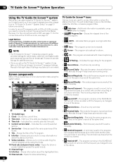
... remote buttons you press TV GUIDE. This is highlighted. From the Listings screen you can consider the Listings screen as the / and / buttons on the Media Receiver. Press to set the highlighted program to display a panel menu. ENTER Press to change the frequency of information (where applicable).
... remote buttons you press TV GUIDE. This is highlighted. From the Listings screen you can consider the Listings screen as the / and / buttons on the Media Receiver. Press to set the highlighted program to display a panel menu. ENTER Press to change the frequency of information (where applicable).

Owner's Manual
Page 63
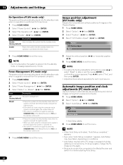
... 5 Press HOME MENU to save power. Energy Save You may not be placed into the standby mode if no signal is received for 15 minutes. 1 Press HOME MENU. 2 Select "Power Control". ( / then ENTER) 3 Select "No Signal off ...drop level. Save2 Decreases the picture brightness and lowers power consumption. NOTE • Five minutes before the system is received for 15 minutes. 5 Press HOME MENU to exit the menu. Picture Off Deactivates the screen to exit the menu...the system into the standby mode when noise signals are present at the Media Receiver after a TV program finishes. 63 En
... 5 Press HOME MENU to save power. Energy Save You may not be placed into the standby mode if no signal is received for 15 minutes. 1 Press HOME MENU. 2 Select "Power Control". ( / then ENTER) 3 Select "No Signal off ...drop level. Save2 Decreases the picture brightness and lowers power consumption. NOTE • Five minutes before the system is received for 15 minutes. 5 Press HOME MENU to exit the menu. Picture Off Deactivates the screen to exit the menu...the system into the standby mode when noise signals are present at the Media Receiver after a TV program finishes. 63 En
Owner's Manual
Page 64
...HOME MENU. 2 Select "Power Control". ( / then ENTER) 3 Select "No Operation off . • The system is switched on again by pressing STANDBY/ON on the Media Receiver or TV on the remote control unit. 5 Press HOME MENU to exit the menu. 5 Adjust the vertical position ( / ) or horizontal position ( / ). 6 Press ... Adjust Reset 5 Press HOME MENU to exit the menu. NOTE • Five minutes before starting Auto Setup. 64 En Press / to the Media Receiver and switch it on before the system is finished, "Auto Setup completed." appears, Auto Setup may fail with a PC image composed of images ...
...HOME MENU. 2 Select "Power Control". ( / then ENTER) 3 Select "No Operation off . • The system is switched on again by pressing STANDBY/ON on the Media Receiver or TV on the remote control unit. 5 Press HOME MENU to exit the menu. 5 Adjust the vertical position ( / ) or horizontal position ( / ). 6 Press ... Adjust Reset 5 Press HOME MENU to exit the menu. NOTE • Five minutes before starting Auto Setup. 64 En Press / to the Media Receiver and switch it on before the system is finished, "Auto Setup completed." appears, Auto Setup may fail with a PC image composed of images ...
Owner's Manual
Page 68
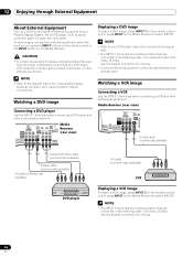
...power outlet before making connections. NOTE • Refer to the relevant instruction manual (DVD player, personal computer, etc.) carefully before connecting to select INPUT2. Media Receiver (rear view) MONITOR OUT ANT/ CABLE A IN INPUT 2 G-LINK INPUT 3 I N OUT CONTROL ANT B IN SERVICE ONLY R-AUDIO-L VIDEO S-...DVD player Displaying a VCR image To watch a DVD image, press INPUT 1 on the remote control unit or press INPUT on the Media Receiver to a DVD player, VCR, personal computer, game console, camcorder, or other external equipment. NOTE • Refer to your DVD ...
...power outlet before making connections. NOTE • Refer to the relevant instruction manual (DVD player, personal computer, etc.) carefully before connecting to select INPUT2. Media Receiver (rear view) MONITOR OUT ANT/ CABLE A IN INPUT 2 G-LINK INPUT 3 I N OUT CONTROL ANT B IN SERVICE ONLY R-AUDIO-L VIDEO S-...DVD player Displaying a VCR image To watch a DVD image, press INPUT 1 on the remote control unit or press INPUT on the Media Receiver to a DVD player, VCR, personal computer, game console, camcorder, or other external equipment. NOTE • Refer to your DVD ...


