Owner's Manual
Page 4
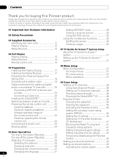
... User Guidance Information 02 Safety Precautions 03 Supplied Accessories Identifying the main units 12 Plasma Display 12 Media Receiver 12 04 Part Names Plasma Display 13 Media Receiver 14 Remote control unit 16 Setting MTS/SAP mode 28 Viewing a channel banner 29 Using the POD service 29 Using the multiscreen functions 29 Splitting the screen 29 Freezing images 30 07 TV Guide On Screen™ System Setup About the TV Guide On Screen™ system 31 Setting up closed captions...
... User Guidance Information 02 Safety Precautions 03 Supplied Accessories Identifying the main units 12 Plasma Display 12 Media Receiver 12 04 Part Names Plasma Display 13 Media Receiver 14 Remote control unit 16 Setting MTS/SAP mode 28 Viewing a channel banner 29 Using the POD service 29 Using the multiscreen functions 29 Splitting the screen 29 Freezing images 30 07 TV Guide On Screen™ System Setup About the TV Guide On Screen™ system 31 Setting up closed captions...

Owner's Manual
Page 5
... images 69 Changing the System Settings 55 Connecting a game console or Changing the Channel Display camcorder 69 settings 56 Displaying an image of the game Changing the Default Options 57 11 Adjustments and Settings Sleep Timer 58 AV Selection 58 Basic picture adjustments 59 Advanced picture adjustments 60 Using PureCinema 60 Using Color Temp 60 Using CTI 60 Eliminating noise from images 61 Sound adjustments 61 FOCUS 62 Front Surround 62 Power Control 62 Energy Save 62 No Signal off (AV mode...
... images 69 Changing the System Settings 55 Connecting a game console or Changing the Channel Display camcorder 69 settings 56 Displaying an image of the game Changing the Default Options 57 11 Adjustments and Settings Sleep Timer 58 AV Selection 58 Basic picture adjustments 59 Advanced picture adjustments 60 Using PureCinema 60 Using Color Temp 60 Using CTI 60 Eliminating noise from images 61 Sound adjustments 61 FOCUS 62 Front Surround 62 Power Control 62 Energy Save 62 No Signal off (AV mode...
Owner's Manual
Page 7
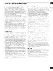
... product tilted over except in the case of vertical installation of the Media Receiver. • Do not invert the product. With the Pioneer PureVision PDP-5060HD/PDP-4360HD, you can be installed by using the still picture mode from a TV, VCR, DVD player or any still image, it is strongly recommended. This improves the color / picture reproduction of these models as such, are typical effects and characteristics of...
... product tilted over except in the case of vertical installation of the Media Receiver. • Do not invert the product. With the Pioneer PureVision PDP-5060HD/PDP-4360HD, you can be installed by using the still picture mode from a TV, VCR, DVD player or any still image, it is strongly recommended. This improves the color / picture reproduction of these models as such, are typical effects and characteristics of...
Owner's Manual
Page 10
.... Replacement parts-In case the product needs replacement parts, make sure that the product needs servicing. 18. Heat sources-Keep the product away from the cart. 10. Keep this product is made of power supply used in your home, consult your product, please read and understood before installing the speakers. 23. Use only the mounting hardware recommended by broken glass pieces in case the plasma Display breaks...
.... Replacement parts-In case the product needs replacement parts, make sure that the product needs servicing. 18. Heat sources-Keep the product away from the cart. 10. Keep this product is made of power supply used in your home, consult your product, please read and understood before installing the speakers. 23. Use only the mounting hardware recommended by broken glass pieces in case the plasma Display breaks...

Owner's Manual
Page 15
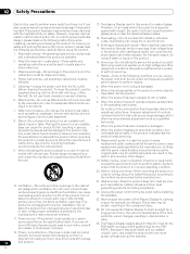
... INPUT 1 INPUT 3 HDMI BLACK WHITE SYSTEM CABLE AC IN 17 9 10 11 12 13 14 1516 18 19 20 21 1 ANT/CABLE A IN terminal 2 MONITOR OUT terminals (AUDIO) 3 MONITOR OUT terminal (VIDEO) 4 G-LINK terminal 5 i.LINK terminals 6 SUB WOOFER terminal 7 DIGITAL OUT terminal (OPTICAL) 8 CableCARD™ slot 9 CONTROL IN terminal 10 CONTROL OUT terminal 11 ANT B IN terminal 12 RS-232C terminal (used for factory setup) 13 INPUT 2 terminals (AUDIO) 22...
... INPUT 1 INPUT 3 HDMI BLACK WHITE SYSTEM CABLE AC IN 17 9 10 11 12 13 14 1516 18 19 20 21 1 ANT/CABLE A IN terminal 2 MONITOR OUT terminals (AUDIO) 3 MONITOR OUT terminal (VIDEO) 4 G-LINK terminal 5 i.LINK terminals 6 SUB WOOFER terminal 7 DIGITAL OUT terminal (OPTICAL) 8 CableCARD™ slot 9 CONTROL IN terminal 10 CONTROL OUT terminal 11 ANT B IN terminal 12 RS-232C terminal (used for factory setup) 13 INPUT 2 terminals (AUDIO) 22...
Owner's Manual
Page 16
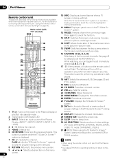
...: Displays a channel banner when a TV program is displayed. 31 (REC): When using the remote control unit, point it into standby mode. 27 DISPLAY: Displays the channel information. 2 Transmission confirmation LED 28 SCREEN SIZE: Selects the screen size. 3 INPUT: Selects an input source of program listings in dark 10 25 places. 11 26 18 ANT: Selects the antenna (A, B). For the buttons for operating buttons not listed on this 9 / / / : Selects a desired item on the remote control 8 22 unit will turn...
...: Displays a channel banner when a TV program is displayed. 31 (REC): When using the remote control unit, point it into standby mode. 27 DISPLAY: Displays the channel information. 2 Transmission confirmation LED 28 SCREEN SIZE: Selects the screen size. 3 INPUT: Selects an input source of program listings in dark 10 25 places. 11 26 18 ANT: Selects the antenna (A, B). For the buttons for operating buttons not listed on this 9 / / / : Selects a desired item on the remote control 8 22 unit will turn...

Owner's Manual
Page 21
... the remote control unit. • While watching a broadcast, press ANT to view the image received from the Cable Converter. Tab Switching between antenna A and B To watch broadcasts via the two antennas, you need not execute Auto Channel Preset; S400 (TS) R-AUDIO-L DIOGPITTAICLASOLUUBT WOOFER Cable CARD BLACK WHITE STEM CABLE NOTE • Be sure to use a CableCARD™, you can select it goes. This service presents various types of useful information, using HTML...
... the remote control unit. • While watching a broadcast, press ANT to view the image received from the Cable Converter. Tab Switching between antenna A and B To watch broadcasts via the two antennas, you need not execute Auto Channel Preset; S400 (TS) R-AUDIO-L DIOGPITTAICLASOLUUBT WOOFER Cable CARD BLACK WHITE STEM CABLE NOTE • Be sure to use a CableCARD™, you can select it goes. This service presents various types of useful information, using HTML...
Owner's Manual
Page 23
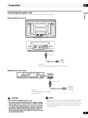
Media Receiver (rear view) MONITOR OUT ANT/ CABLE A IN INPUT 2 G-LINK INPUT 3 S400 (TS) R-AUDIO-L OPTICAL DIGITAL OUT SUB WOOFER Cable CARD I N OUT CONTROL ANT B IN SERVICE ONLY R-AUDIO-L VIDEO S-VIDEO INPUT 1 Y CB / PB COMPONENT VIDEO CR / PR INPUT 1 INPUT 3 HDMI BLACK WHITE SYSTEM CABLE AC IN AC IN Power cord Noise filter Partially eliminates noise caused by the power source. neglecting this can result in fire or electric shock. • For the Plasma Display System, a three-core power cord with a ground terminal is used for...
Media Receiver (rear view) MONITOR OUT ANT/ CABLE A IN INPUT 2 G-LINK INPUT 3 S400 (TS) R-AUDIO-L OPTICAL DIGITAL OUT SUB WOOFER Cable CARD I N OUT CONTROL ANT B IN SERVICE ONLY R-AUDIO-L VIDEO S-VIDEO INPUT 1 Y CB / PB COMPONENT VIDEO CR / PR INPUT 1 INPUT 3 HDMI BLACK WHITE SYSTEM CABLE AC IN AC IN Power cord Noise filter Partially eliminates noise caused by the power source. neglecting this can result in fire or electric shock. • For the Plasma Display System, a three-core power cord with a ground terminal is used for...
Owner's Manual
Page 31
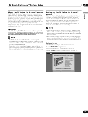
... receive updated TV program listings (see Screen 14). • If you connect a cable box through the setup process. Follow the instructions shown on page 32). 31 En Or press TV GUIDE to begin to receive TV program listings. Welcome Screen Initial TV set up leads you set up the TV Guide On Screen™ system it up. The system offers program listings, searching by Gemstar-TV Guide International, Inc. The TV Guide On Screen...
... receive updated TV program listings (see Screen 14). • If you connect a cable box through the setup process. Follow the instructions shown on page 32). 31 En Or press TV GUIDE to begin to receive TV program listings. Welcome Screen Initial TV set up leads you set up the TV Guide On Screen™ system it up. The system offers program listings, searching by Gemstar-TV Guide International, Inc. The TV Guide On Screen...
Owner's Manual
Page 39
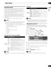
... be newly set, using buttons 0 - 9. 8 Enter the same password that you to watch a program (or content) blocked by the Motion Picture Association of such programs, see pages 41 and 42. Changing the password Using a password prevents other persons from watching inappropriate TV programs, VCR or DVD contents. Tuner Setup 09 English Parental Control With the Parental Control, parents can prevent their children from changing Parental Control settings. The Parental Control functions...
... be newly set, using buttons 0 - 9. 8 Enter the same password that you to watch a program (or content) blocked by the Motion Picture Association of such programs, see pages 41 and 42. Changing the password Using a password prevents other persons from watching inappropriate TV programs, VCR or DVD contents. Tuner Setup 09 English Parental Control With the Parental Control, parents can prevent their children from changing Parental Control settings. The Parental Control functions...
Owner's Manual
Page 46
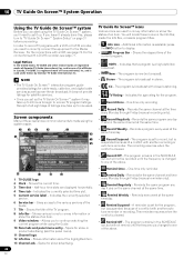
... this, please turn to display. • Progress Bar - 10 TV Guide On Screen™ System Operation TV Guide On Screen™ System Operation Using the TV Guide On Screen™ system Before you can start using the TV Guide On Screen™ system, you'll need to correctly connect the equipment to the Media Receiver. One-time only recording • Record Daily - The program is set to one week...
... this, please turn to display. • Progress Bar - 10 TV Guide On Screen™ System Operation TV Guide On Screen™ System Operation Using the TV Guide On Screen™ system Before you can start using the TV Guide On Screen™ system, you'll need to correctly connect the equipment to the Media Receiver. One-time only recording • Record Daily - The program is set to one week...

Owner's Manual
Page 67
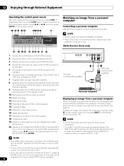
...select the input source using the INPUT buttons on the remote control or the INPUT button on the Media Receiver to a DVD player, VCR, personal computer, game console, camcorder, or other external equipment. Use the desired connection for viewing. 67 En MONITOR OUT ANT/ CABLE A IN INPUT 2 G-LINK INPUT 3 S400 (TS) R-AUDIO-L OPTICAL DIGITAL OUT SUB WOOFER Media Receiver (rear view) SERVICE ONLY R-AUDIO-L VIDEO S-VIDEO INPUT 1 Y CB / PB COMPONENT VIDEO CR / PR INPUT 1 HD Displaying a DVD image To watch a VCR image, press INPUT 2 on the remote control unit or press INPUT on the...
...select the input source using the INPUT buttons on the remote control or the INPUT button on the Media Receiver to a DVD player, VCR, personal computer, game console, camcorder, or other external equipment. Use the desired connection for viewing. 67 En MONITOR OUT ANT/ CABLE A IN INPUT 2 G-LINK INPUT 3 S400 (TS) R-AUDIO-L OPTICAL DIGITAL OUT SUB WOOFER Media Receiver (rear view) SERVICE ONLY R-AUDIO-L VIDEO S-VIDEO INPUT 1 Y CB / PB COMPONENT VIDEO CR / PR INPUT 1 HD Displaying a DVD image To watch a VCR image, press INPUT 2 on the remote control unit or press INPUT on the...

Owner's Manual
Page 68
... HDMI terminal. (factory default) Enable Activates the HDMI terminal. 6 Press HOME MENU to select INPUT 1 (or INPUT 3). NOTE • If you select a parameter other than "Auto", make such a setting that results in natural color. • If no image appears, specify another digital video signal type. • For the digital video signal types to identify the type of digital video signals when digital video signals are not supported. Connecting HDMI equipment Media Receiver (rear view) MONITOR OUT ANT/ CABLE A IN INPUT 2 G-LINK INPUT 3 S400 (TS) R-AUDIO-L OPTICAL DIGITAL...
... HDMI terminal. (factory default) Enable Activates the HDMI terminal. 6 Press HOME MENU to select INPUT 1 (or INPUT 3). NOTE • If you select a parameter other than "Auto", make such a setting that results in natural color. • If no image appears, specify another digital video signal type. • For the digital video signal types to identify the type of digital video signals when digital video signals are not supported. Connecting HDMI equipment Media Receiver (rear view) MONITOR OUT ANT/ CABLE A IN INPUT 2 G-LINK INPUT 3 S400 (TS) R-AUDIO-L OPTICAL DIGITAL...

Owner's Manual
Page 70
...B IN SERVICE ONLY R-AUDIO-L VIDEO S-VIDEO INPUT 1 Y CB / PB COMPONENT VIDEO CR / PR INPUT 1 INPUT 3 HDMI BLACK SYSTEM AV cable (commercially available) Connecting other than external input sources. NOTE • When using the digital audio output terminal (optical), you need to other TV sets. Do not connect through External Equipment Connecting a recorder Media Receiver (rear view) MONITOR OUT ANT/ CABLE A IN INPUT 2 G-LINK INPUT 3 S400 (TS) R-AUDIO-L OPTICAL DIGITAL OUT SUB WOOFER Cable CARD I N OUT CONTROL ANT B IN SERVICE ONLY R-AUDIO-L VIDEO S-VIDEO INPUT...
...B IN SERVICE ONLY R-AUDIO-L VIDEO S-VIDEO INPUT 1 Y CB / PB COMPONENT VIDEO CR / PR INPUT 1 INPUT 3 HDMI BLACK SYSTEM AV cable (commercially available) Connecting other than external input sources. NOTE • When using the digital audio output terminal (optical), you need to other TV sets. Do not connect through External Equipment Connecting a recorder Media Receiver (rear view) MONITOR OUT ANT/ CABLE A IN INPUT 2 G-LINK INPUT 3 S400 (TS) R-AUDIO-L OPTICAL DIGITAL OUT SUB WOOFER Cable CARD I N OUT CONTROL ANT B IN SERVICE ONLY R-AUDIO-L VIDEO S-VIDEO INPUT...

Owner's Manual
Page 71
... programs. You cannot record conventional TV channels nor contents coming from external input sources and personal computers. i.LINK cable Media Receiver STANDBY/ON REC ON STANDBY TIMER PULL OPEN D-VHS recorder D-VHS recorder 71 En With D-VHS recorders connected to exit the menu. Dolby Digital For Dolby Digital encoded signals, outputs in the PCM format. When connecting a single D-VHS recorder Media Receiver (rear view) MONITOR OUT ANT/ CABLE A IN INPUT 2 G-LINK INPUT 3 S400 (TS) R-AUDIO-L OPTICAL DIGITAL OUT SUB WOOFER Cable CARD NT B N SERVICE...
... programs. You cannot record conventional TV channels nor contents coming from external input sources and personal computers. i.LINK cable Media Receiver STANDBY/ON REC ON STANDBY TIMER PULL OPEN D-VHS recorder D-VHS recorder 71 En With D-VHS recorders connected to exit the menu. Dolby Digital For Dolby Digital encoded signals, outputs in the PCM format. When connecting a single D-VHS recorder Media Receiver (rear view) MONITOR OUT ANT/ CABLE A IN INPUT 2 G-LINK INPUT 3 S400 (TS) R-AUDIO-L OPTICAL DIGITAL OUT SUB WOOFER Cable CARD NT B N SERVICE...

Owner's Manual
Page 72
... following loop connections: Media Receiver REC ON STANDBY TIMER STANDBY/ON D-VHS recorder PULL OPEN D-VHS recorder Media Receiver STANDBY/ON REC ON STANDBY TIMER PULL OPEN D-VHS recorder Displaying a D-VHS image To watch a D-VHS image, press i.LINK on the remote control unit or press INPUT on the Media Receiver to INPUT 1, 2, 3, or 4 terminals on or off . Precautions • While one i.LINK device to play back digital TV programs recorded using connected D-VHS recorders, use VHS...
... following loop connections: Media Receiver REC ON STANDBY TIMER STANDBY/ON D-VHS recorder PULL OPEN D-VHS recorder Media Receiver STANDBY/ON REC ON STANDBY TIMER PULL OPEN D-VHS recorder Displaying a D-VHS image To watch a D-VHS image, press i.LINK on the remote control unit or press INPUT on the Media Receiver to INPUT 1, 2, 3, or 4 terminals on or off . Precautions • While one i.LINK device to play back digital TV programs recorded using connected D-VHS recorders, use VHS...
Owner's Manual
Page 74
... the next program. 18 Forwards the tape. 19 Exits the control panel screen and displays the i.LINK Setup menu. 20 Allows you have set up to select the desired model from a personal computer When connected to be used for S- To watch an image coming from a personal computer Connecting a personal computer Use the PC terminals to these terminals, the same signal type is in the standby mode. 10 Switches the...
... the next program. 18 Forwards the tape. 19 Exits the control panel screen and displays the i.LINK Setup menu. 20 Allows you have set up to select the desired model from a personal computer When connected to be used for S- To watch an image coming from a personal computer Connecting a personal computer Use the PC terminals to these terminals, the same signal type is in the standby mode. 10 Switches the...

Owner's Manual
Page 76
... Guide On Screen™ system works with your VCR. G-LINK cable (supplied) Media Receiver (rear view) MONITOR OUT ANT/ CABLE A IN INPUT 2 G-LINK INPUT 3 S400 (TS) R-AUDIO-L OPTICAL DIGITAL OUT SUB WOOFER Cable CAR I N OUT CONTROL ANT B IN SERVICE ONLY R-AUDIO-L VIDEO S-VIDEO INPUT 1 Y CB / PB COMPONENT VIDEO CR / PR INPUT 1 INPUT 3 HDMI AV cable (commercially available) AV cable (commercially available) G-LINK cable's wand Point to the remote control sensor VCR Cable box G-LINK cable's wand Point to other TV sets. 12 Enjoying through a VCR. • Use...
... Guide On Screen™ system works with your VCR. G-LINK cable (supplied) Media Receiver (rear view) MONITOR OUT ANT/ CABLE A IN INPUT 2 G-LINK INPUT 3 S400 (TS) R-AUDIO-L OPTICAL DIGITAL OUT SUB WOOFER Cable CAR I N OUT CONTROL ANT B IN SERVICE ONLY R-AUDIO-L VIDEO S-VIDEO INPUT 1 Y CB / PB COMPONENT VIDEO CR / PR INPUT 1 INPUT 3 HDMI AV cable (commercially available) AV cable (commercially available) G-LINK cable's wand Point to the remote control sensor VCR Cable box G-LINK cable's wand Point to other TV sets. 12 Enjoying through a VCR. • Use...

Owner's Manual
Page 77
... the input switch linkage operation function and the DSP surround mode display function. NOTE • Make sure that came with the PIONEER AV receiver supporting SR+. Face the remote control units to the remote control sensor on the Plasma Display when operating the connected equipment. Media Receiver (rear view) CONTROL MONITOR OUT ANT/ CABLE A IN INPUT 2 G-LINK INPUT 3 S400 (TS) R-AUDIO-L OPTICAL DIGITAL OUT SUB WOOFER Cable CARD I N OUT CONTROL ANT B IN SERVICE ONLY R-AUDIO-L VIDEO S-VIDEO INPUT 1 Y CB / PB COMPONENT VIDEO CR / PR INPUT 1 INPUT 3 HDMI BLACK WH...
... the input switch linkage operation function and the DSP surround mode display function. NOTE • Make sure that came with the PIONEER AV receiver supporting SR+. Face the remote control units to the remote control sensor on the Plasma Display when operating the connected equipment. Media Receiver (rear view) CONTROL MONITOR OUT ANT/ CABLE A IN INPUT 2 G-LINK INPUT 3 S400 (TS) R-AUDIO-L OPTICAL DIGITAL OUT SUB WOOFER Cable CARD I N OUT CONTROL ANT B IN SERVICE ONLY R-AUDIO-L VIDEO S-VIDEO INPUT 1 Y CB / PB COMPONENT VIDEO CR / PR INPUT 1 INPUT 3 HDMI BLACK WH...
Owner's Manual
Page 85
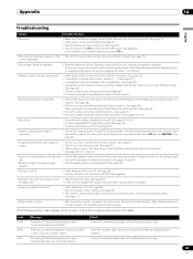
...; Is picture adjustment correct? (See page 59.) • Audio is output but no audio is suddenly turned off. • Panel sounds / noises • Is the sleep timer set correctly? Powering off . Internal temperature too high. Check the speaker cable connections between the right and left or if the speaker cable left. Check if the ambient temperature of the Plasma Display and the Media Receiver, or unplugging the power cord and re-plugging it...
...; Is picture adjustment correct? (See page 59.) • Audio is output but no audio is suddenly turned off. • Panel sounds / noises • Is the sleep timer set correctly? Powering off . Internal temperature too high. Check the speaker cable connections between the right and left or if the speaker cable left. Check if the ambient temperature of the Plasma Display and the Media Receiver, or unplugging the power cord and re-plugging it...


