
Owner's Manual
Page 9
...the service person uses replacement parts specified by the manufacturer. 21. Heat sources-Keep the product away from the AC outlet before installing the speakers. 23. Unplug the power cord from heat sources such as the original parts. Never expose the screen of the front protection panel changes..., be broken, resulting in fire, electric shock and/or other heat- Use M8 screws, which go 12 to a strong impact, for the PDP-434PU. Safety Precautions 02 English 18. The optical characteristics of the Plasma Display to 18 mm in proper operating condition. 20. Replacement parts-In ...
...the service person uses replacement parts specified by the manufacturer. 21. Heat sources-Keep the product away from the AC outlet before installing the speakers. 23. Unplug the power cord from heat sources such as the original parts. Never expose the screen of the front protection panel changes..., be broken, resulting in fire, electric shock and/or other heat- Use M8 screws, which go 12 to a strong impact, for the PDP-434PU. Safety Precautions 02 English 18. The optical characteristics of the Plasma Display to 18 mm in proper operating condition. 20. Replacement parts-In ...

Owner's Manual
Page 12
05 Supplied Accessories Plasma Display Power cord (2 m/6.6 feet) Cleaning cloth Speed clamp x 3 Bead band x 3 Media Receiver Warranty card Speaker cushion x 3 (Use when installing the optional speakers at the bottom of the Plasma Display.) Power cord (2 m/6.6 feet) Remote control unit System cable (3 m/9.8 feet) AA size battery x 2 (Alkaline battery) Stand Screw x 4 (for stand) ...
05 Supplied Accessories Plasma Display Power cord (2 m/6.6 feet) Cleaning cloth Speed clamp x 3 Bead band x 3 Media Receiver Warranty card Speaker cushion x 3 (Use when installing the optional speakers at the bottom of the Plasma Display.) Power cord (2 m/6.6 feet) Remote control unit System cable (3 m/9.8 feet) AA size battery x 2 (Alkaline battery) Stand Screw x 4 (for stand) ...

Owner's Manual
Page 13
Part Names Plasma Display Front view 06 (right view) 5 6 7 8 English 2 1 3 1 POWER button 2 STANDBY indicator 3 POWER ON indicator 4 Remote control sensor 4 5 STANDBY/ON button 6 INPUT button 7 VOLUME +/- buttons 8 CHANNEL +/- buttons Rear view 9 - 0 = 9 SYSTEM CABLE terminal (BLACK) 0 SYSTEM CABLE terminal (WHITE) The terminals have faced downward. - SPEAKER (right/left) terminals = AC INLET terminal PDP5040HD-Eng (13-16) 13 13 En 7/24/03, 1:57 PM
Part Names Plasma Display Front view 06 (right view) 5 6 7 8 English 2 1 3 1 POWER button 2 STANDBY indicator 3 POWER ON indicator 4 Remote control sensor 4 5 STANDBY/ON button 6 INPUT button 7 VOLUME +/- buttons 8 CHANNEL +/- buttons Rear view 9 - 0 = 9 SYSTEM CABLE terminal (BLACK) 0 SYSTEM CABLE terminal (WHITE) The terminals have faced downward. - SPEAKER (right/left) terminals = AC INLET terminal PDP5040HD-Eng (13-16) 13 13 En 7/24/03, 1:57 PM
Owner's Manual
Page 17
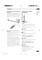
... within 30 degrees in instability causing possible injury. • Depending on installation, refer to the instruction manual provided with the speaker. If you place such equipment operated through infrared remote control as a VCR nearby, that equipment at the bottom right of ... the right, left, upward, or downward direction. The strength of infrared rays emitted from the remote control sensor. Using the optional PIONEER speakers • For details on installation, refer to sunlight • Under strong artificial light • In high humidity • Poorly ventilated...
... within 30 degrees in instability causing possible injury. • Depending on installation, refer to the instruction manual provided with the speaker. If you place such equipment operated through infrared remote control as a VCR nearby, that equipment at the bottom right of ... the right, left, upward, or downward direction. The strength of infrared rays emitted from the remote control sensor. Using the optional PIONEER speakers • For details on installation, refer to sunlight • Under strong artificial light • In high humidity • Poorly ventilated...
Owner's Manual
Page 20
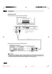
...Setting the system Connecting the system cable to the Plasma Display Plasma Display (rear view) (WHITE) (BLACK) For details on optional PIONEER speaker installation, refer to the Media Receiver Media Receiver (rear view) SERVICE ONLY IN OUT CONTROL VCR CONTROL IN OUT IN OUT S-VIDEO...-L INPUT 3 Y CB/PB CR/PR AC INLET BLACK WHITE SYSTEM CABLE (BLACK) (WHITE) • THESE SPEAKER TERMINALS CAN BE UNDER HAZARDOUS VOLTAGE WHEN YOU CONNECT OR DISCONNECT THE SPEAKER CABLES. TO PREVENT THE RISK OF ELECTRIC SHOCK, DO NOT TOUCH UNINSULATED PARTS BEFORE DISCONNECTING THE POWER CORD. 20...
...Setting the system Connecting the system cable to the Plasma Display Plasma Display (rear view) (WHITE) (BLACK) For details on optional PIONEER speaker installation, refer to the Media Receiver Media Receiver (rear view) SERVICE ONLY IN OUT CONTROL VCR CONTROL IN OUT IN OUT S-VIDEO...-L INPUT 3 Y CB/PB CR/PR AC INLET BLACK WHITE SYSTEM CABLE (BLACK) (WHITE) • THESE SPEAKER TERMINALS CAN BE UNDER HAZARDOUS VOLTAGE WHEN YOU CONNECT OR DISCONNECT THE SPEAKER CABLES. TO PREVENT THE RISK OF ELECTRIC SHOCK, DO NOT TOUCH UNINSULATED PARTS BEFORE DISCONNECTING THE POWER CORD. 20...
Owner's Manual
Page 21
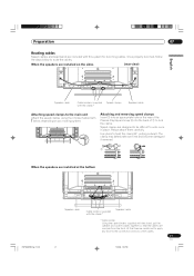
... together so that time be difficult to undo once in place. At that the cables are installed on your routing system. When the speakers are invisible from the front. Please attach them carefully. Speed clamps are included with below to route the cables. Once properly bunched, ...follow the steps below , depending on the sides (rear view) English Speaker cable Cable binders (supplied Speed clamps with the stand)* Speaker cable Attaching speed clamps to the main unit Attach the speed clamps using the 4 holes marked with this system ...
... together so that time be difficult to undo once in place. At that the cables are installed on your routing system. When the speakers are invisible from the front. Please attach them carefully. Speed clamps are included with below to route the cables. Once properly bunched, ...follow the steps below , depending on the sides (rear view) English Speaker cable Cable binders (supplied Speed clamps with the stand)* Speaker cable Attaching speed clamps to the main unit Attach the speed clamps using the 4 holes marked with this system ...

Owner's Manual
Page 38
Adjusts the picture between left and right speakers. 52 All audio adjustment settings return to the factory defaults. 52 Shift the sound coming direction (sound images) upward and produces clear sound contours. 53 ...
Adjusts the picture between left and right speakers. 52 All audio adjustment settings return to the factory defaults. 52 Shift the sound coming direction (sound images) upward and produces clear sound contours. 53 ...

Owner's Manual
Page 39
... weaker or stronger. 52 Adjusts the bass weaker or stronger. 52 Adjusts audio output between light and shade. Adjusts the picture between left and right speakers. 52 All audio adjustment settings return to the factory defaults. 52 Shifts the sound coming direction (sound images) upward and produces clear sound contours. 53...
... weaker or stronger. 52 Adjusts the bass weaker or stronger. 52 Adjusts audio output between light and shade. Adjusts the picture between left and right speakers. 52 All audio adjustment settings return to the factory defaults. 52 Shifts the sound coming direction (sound images) upward and produces clear sound contours. 53...

Owner's Manual
Page 52
... Bass Balance button For weaker treble button For stronger treble For weaker bass For stronger bass Decreases audio from Decreases audio from the right speaker the left speaker 4 Press HOME MENU to exit the menu. • To restore the factory defaults for all the items, press / to your preference for the chosen...
... Bass Balance button For weaker treble button For stronger treble For weaker bass For stronger bass Decreases audio from Decreases audio from the right speaker the left speaker 4 Press HOME MENU to exit the menu. • To restore the factory defaults for all the items, press / to your preference for the chosen...
Owner's Manual
Page 106
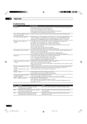
.... (See pages 13 and 20.) • Sound is output from only a single • Has the balance been correctly adjusted? (See page 52.) speaker. • Picture is cut off . The picture may cause improper operation. Powering off . • Is the image position correct? (See pages 81and...page 31.) • When using a video or PC input source, check that is too bright. • Power is also in speaker cable? Check temperature around PDP. 14 Appendix Troubleshooting Problem • No power. Possible Solution • Make sure the Plasma Display and the Media Receiver are connected ...
.... (See pages 13 and 20.) • Sound is output from only a single • Has the balance been correctly adjusted? (See page 52.) speaker. • Picture is cut off . The picture may cause improper operation. Powering off . • Is the image position correct? (See pages 81and...page 31.) • When using a video or PC input source, check that is too bright. • Power is also in speaker cable? Check temperature around PDP. 14 Appendix Troubleshooting Problem • No power. Possible Solution • Make sure the Plasma Display and the Media Receiver are connected ...


