Owner's Manual
Page 3
... or other equipment. If this equipment is connected. - Product Name: Plasma Display System (Plasma Display) (Media Receiver) Model Number: PDP-5045HD PDP-4345HD (PDP-504PU) (PDP-434PU) (PDP-R05U) (PDP-R05U) Product Category: Class B Personal Computers & Peripherals Responsible Party Name: PIONEER ELECTRONICS (USA), INC., Customer Support Div. To prevent electromagnetic interference with the product will not occur in accordance with part 15 of California and other governmental entities to...
... or other equipment. If this equipment is connected. - Product Name: Plasma Display System (Plasma Display) (Media Receiver) Model Number: PDP-5045HD PDP-4345HD (PDP-504PU) (PDP-434PU) (PDP-R05U) (PDP-R05U) Product Category: Class B Personal Computers & Peripherals Responsible Party Name: PIONEER ELECTRONICS (USA), INC., Customer Support Div. To prevent electromagnetic interference with the product will not occur in accordance with part 15 of California and other governmental entities to...
Owner's Manual
Page 4
.../UHF antennas 21 Switching between antenna A and B 22 Inserting the cable card 22 Connecting the power cord 23 07 Basic Operations Turning on the power 24 Turning off the power 24 Watching TV channels 25 Selecting the antenna 25 Changing channels 25 Changing the volume and sound 26 Viewing a channel banner 26 Using the POD service 27 Changing the language 27 Setting MTS/SAP mode 27 Using the multiscreen functions 28 Splitting the screen 28 Freezing images 29 08 Menu Setup Menu...
.../UHF antennas 21 Switching between antenna A and B 22 Inserting the cable card 22 Connecting the power cord 23 07 Basic Operations Turning on the power 24 Turning off the power 24 Watching TV channels 25 Selecting the antenna 25 Changing channels 25 Changing the volume and sound 26 Viewing a channel banner 26 Using the POD service 27 Changing the language 27 Setting MTS/SAP mode 27 Using the multiscreen functions 28 Splitting the screen 28 Freezing images 29 08 Menu Setup Menu...
Owner's Manual
Page 5
... mode only 45 Adjusting image positions and clock manually (PC mode only 45 Selecting a screen size 46 Changing the brightness at both sides of the screen (Side Mask 47 Language setting 47 11 Timer Presetting Presetting TV programs using the timer 48 Priority rules for overlapped presettings 49 12 Enjoying through External Equipment Watching a DVD image 50 Connecting a DVD player 50 Displaying a DVD image 50 Watching a VCR image 50 Connecting a VCR 50 Displaying a VCR image 50 Using HDMI Input 51 Connecting HDMI...
... mode only 45 Adjusting image positions and clock manually (PC mode only 45 Selecting a screen size 46 Changing the brightness at both sides of the screen (Side Mask 47 Language setting 47 11 Timer Presetting Presetting TV programs using the timer 48 Priority rules for overlapped presettings 49 12 Enjoying through External Equipment Watching a DVD image 50 Connecting a DVD player 50 Displaying a DVD image 50 Watching a VCR image 50 Connecting a VCR 50 Displaying a VCR image 50 Using HDMI Input 51 Connecting HDMI...
Owner's Manual
Page 6
... the existence of a minute number of the Pioneer PDP-5045HD/PDP-4345HD Plasma Display System will not be affected by PIONEER. Usage guidelines All phosphor-based screens (including conventional tube-type televisions) can ensure longer and satisfactory results from other than 2 hours at a time. • After playing a game, or displaying a PC image or any other components. • Do not leave the same picture freeze-framed or paused...
... the existence of a minute number of the Pioneer PDP-5045HD/PDP-4345HD Plasma Display System will not be affected by PIONEER. Usage guidelines All phosphor-based screens (including conventional tube-type televisions) can ensure longer and satisfactory results from other than 2 hours at a time. • After playing a game, or displaying a PC image or any other components. • Do not leave the same picture freeze-framed or paused...
Owner's Manual
Page 8
... the service person uses replacement parts specified by the manufacturer. 9. Improper adjustment of the front protection panel changes, resulting in the product, and inserting an object can cause damage, which often requires extensive adjustment work , request the service technician to perform safety checks to the product. f. Unplug the power cord from stepping on them . The optical characteristics of controls not described in the instructions can...
... the service person uses replacement parts specified by the manufacturer. 9. Improper adjustment of the front protection panel changes, resulting in the product, and inserting an object can cause damage, which often requires extensive adjustment work , request the service technician to perform safety checks to the product. f. Unplug the power cord from stepping on them . The optical characteristics of controls not described in the instructions can...
Owner's Manual
Page 14
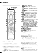
... the 2-screen or picture-in-picture mode. 13 SHIFT: Moves the location of the four preset channels. screen, picture-in dark places. 15 ANT: Selects the antenna (A, B). See page 37 for operating buttons not listed on DTV programs. 10 SPLIT: Switches the screen mode among 2- PC mode: STANDARD, USER.) 27 SLEEP: Sets the sleep timer. • When using the remote control unit, point it into standby mode. 2 Transmission confirmation LED 3 INPUT: Selects an input source of the Plasma Display. (INPUT 1, INPUT 2, INPUT 3, INPUT 4, PC...
... the 2-screen or picture-in-picture mode. 13 SHIFT: Moves the location of the four preset channels. screen, picture-in dark places. 15 ANT: Selects the antenna (A, B). See page 37 for operating buttons not listed on DTV programs. 10 SPLIT: Switches the screen mode among 2- PC mode: STANDARD, USER.) 27 SLEEP: Sets the sleep timer. • When using the remote control unit, point it into standby mode. 2 Transmission confirmation LED 3 INPUT: Selects an input source of the Plasma Display. (INPUT 1, INPUT 2, INPUT 3, INPUT 4, PC...
Owner's Manual
Page 22
... cable TV company; the POD stands for inserting a cable card. Inserting the cable card The Media Receiver is equipped with two video images displayed will switch the selected screen to insert only the specified cable card. • Do not insert a PCMCIA card. See page 21. 2 Hold the tab of the slot cover on the remote control unit. • While watching a broadcast, press ANT to view the image received from the other antenna...
... cable TV company; the POD stands for inserting a cable card. Inserting the cable card The Media Receiver is equipped with two video images displayed will switch the selected screen to insert only the specified cable card. • Do not insert a PCMCIA card. See page 21. 2 Hold the tab of the slot cover on the remote control unit. • While watching a broadcast, press ANT to view the image received from the other antenna...
Owner's Manual
Page 23
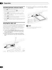
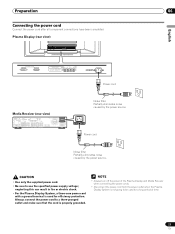
...going to use the specified power supply voltage; Preparation 06 Connecting the power cord Connect the power cord after all component connections have been completed. AC IN Power cord Noise filter Partially eliminates noise caused by the power source. Plasma Display (rear view) English Power cord Media Receiver (rear view) IN OUT CONTROL VCR CONTROL IN ANTENNA B ANTENNA/ CABLE A IN Cable CARD S-VIDEO INPUT 2 INPUT 2 VIDEO R-AUDIO-L DIGITAL OUT OPTICAL (TS) S400 VIDEO INPUT 1 COMPONENT VIDEO R-AUDIO-L Y CB/PB CR/PR SERVICE ONLY OUT MONITOR OUT S-VIDEO VIDEO R-AUDIO...
...going to use the specified power supply voltage; Preparation 06 Connecting the power cord Connect the power cord after all component connections have been completed. AC IN Power cord Noise filter Partially eliminates noise caused by the power source. Plasma Display (rear view) English Power cord Media Receiver (rear view) IN OUT CONTROL VCR CONTROL IN ANTENNA B ANTENNA/ CABLE A IN Cable CARD S-VIDEO INPUT 2 INPUT 2 VIDEO R-AUDIO-L DIGITAL OUT OPTICAL (TS) S400 VIDEO INPUT 1 COMPONENT VIDEO R-AUDIO-L Y CB/PB CR/PR SERVICE ONLY OUT MONITOR OUT S-VIDEO VIDEO R-AUDIO...

Owner's Manual
Page 27
... receives a stereo broadcast. Setting MTS/SAP mode When watching conventional TV programs, you can switch among the languages by pressing MTS on broadcasting signals being received. 27 En STEREO mode SAP mode MONO mode STEREO SAP MONO • In each of useful information, using the MTS button, the display changes depending on the remote control unit. • Conventional TV channels in the standby mode. In this case, sound is in this manual...
... receives a stereo broadcast. Setting MTS/SAP mode When watching conventional TV programs, you can switch among the languages by pressing MTS on broadcasting signals being received. 27 En STEREO mode SAP mode MONO mode STEREO SAP MONO • In each of useful information, using the MTS button, the display changes depending on the remote control unit. • Conventional TV channels in the standby mode. In this case, sound is in this manual...
Owner's Manual
Page 33
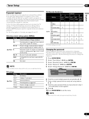
... the following procedure to change the password. 1 Press HOME MENU. 2 Select "Tuner Setup". ( / then ENTER) 3 Select "Parental Control". ( / then ENTER) 4 Select "Password". ( / then ENTER) 5 Select "Change Password". ( / then ENTER) Parental Control Password Password Change Password Clear Password xxxxxxxxxxxxxxxxxxxxx xxxxxxxxxxxxxxxxxxxxx xxxxxxxxxxxxxxxxxxxxx Home Menu Exit 6 Enter the current 4-digit password, using buttons 0 - 9. 7 Enter a 4-digit password to exit the menu. • Take a note of America (MPAA) and are provided by parents, the Plasma Display shows nothing but...
... the following procedure to change the password. 1 Press HOME MENU. 2 Select "Tuner Setup". ( / then ENTER) 3 Select "Parental Control". ( / then ENTER) 4 Select "Password". ( / then ENTER) 5 Select "Change Password". ( / then ENTER) Parental Control Password Password Change Password Clear Password xxxxxxxxxxxxxxxxxxxxx xxxxxxxxxxxxxxxxxxxxx xxxxxxxxxxxxxxxxxxxxx Home Menu Exit 6 Enter the current 4-digit password, using buttons 0 - 9. 7 Enter a 4-digit password to exit the menu. • Take a note of America (MPAA) and are provided by parents, the Plasma Display shows nothing but...

Owner's Manual
Page 50
Media Receiver (rear view) IN OUT VCR CONTROL CONTROL IN ANTENNA B ANTENNA/ CABLE A IN Cable CARD (TS) S400 DIGITAL OUT OPTICAL S-VIDEO INPUT 2 VIDEO R-AUDIO-L VIDEO INPUT 1 COMPONENT VIDEO R-AUDIO-L Y CB/PB CR/PR SERVICE ONLY OUT MONITOR OUT S-VIDEO VIDEO R-AUDIO-L S-VIDEO R-AUDIO-L IINNPUTT 33 Y CB/PB CR/PR INPUT 1 INPUT HDMI AV cable (commercially available) S-Video cable (commercially available) DVD player VCR Displaying a VCR image To watch a DVD image, press INPUT 1 on the remote control unit or press INPUT on the Plasma Display to select INPUT1. • ...
Media Receiver (rear view) IN OUT VCR CONTROL CONTROL IN ANTENNA B ANTENNA/ CABLE A IN Cable CARD (TS) S400 DIGITAL OUT OPTICAL S-VIDEO INPUT 2 VIDEO R-AUDIO-L VIDEO INPUT 1 COMPONENT VIDEO R-AUDIO-L Y CB/PB CR/PR SERVICE ONLY OUT MONITOR OUT S-VIDEO VIDEO R-AUDIO-L S-VIDEO R-AUDIO-L IINNPUTT 33 Y CB/PB CR/PR INPUT 1 INPUT HDMI AV cable (commercially available) S-Video cable (commercially available) DVD player VCR Displaying a VCR image To watch a DVD image, press INPUT 1 on the remote control unit or press INPUT on the Plasma Display to select INPUT1. • ...

Owner's Manual
Page 51
... and audio signals can be received from the connected equipment. Enjoying through External Equipment 12 English Using HDMI Input The INPUT 1 and INPUT 3 terminals include HDMI terminals to identify the type of audio signals when audio signals are not supported. Item Description Auto Automatically identifies input digital video (factory default) signals. Connecting HDMI equipment Media Receiver (rear view) DIGITAL OUT OPTICAL (TS) S400 VIDEO INPUT 1 COMPONENT VIDEO R-AUDIO-L Y CB/PB CR/PR S-VIDEO R-AUDIO-L IINNPUTT 33 Y CB/PB CR/PR INPUT 1 INPUT 3 HDMI Audio cable...
... and audio signals can be received from the connected equipment. Enjoying through External Equipment 12 English Using HDMI Input The INPUT 1 and INPUT 3 terminals include HDMI terminals to identify the type of audio signals when audio signals are not supported. Item Description Auto Automatically identifies input digital video (factory default) signals. Connecting HDMI equipment Media Receiver (rear view) DIGITAL OUT OPTICAL (TS) S400 VIDEO INPUT 1 COMPONENT VIDEO R-AUDIO-L Y CB/PB CR/PR S-VIDEO R-AUDIO-L IINNPUTT 33 Y CB/PB CR/PR INPUT 1 INPUT 3 HDMI Audio cable...

Owner's Manual
Page 52
... images Connecting a game console or camcorder Use the INPUT 4 terminals to exit the menu. Analog Accepts analog audio signals. 6 Press HOME MENU to exit the menu. • If no sound is to be actually used. Connect the VCR controller to the VCR control terminal on the rear of the Media Receiver and then position the controller so that its light emitting section faces the remote control sensor on the rear of images. Media Receiver (front view) COMPONENT VIDEO...
... images Connecting a game console or camcorder Use the INPUT 4 terminals to exit the menu. Analog Accepts analog audio signals. 6 Press HOME MENU to exit the menu. • If no sound is to be actually used. Connect the VCR controller to the VCR control terminal on the rear of the Media Receiver and then position the controller so that its light emitting section faces the remote control sensor on the rear of images. Media Receiver (front view) COMPONENT VIDEO...

Owner's Manual
Page 53
... 4 S-Video signals when Video signals (INPUT 1, 2, and 4) are being input 5 Digital video and audio signals from the HDMI terminals • When watching images played back on a VCR or DVD recorder connected to the MONITOR OUT terminals, select an input source (e.g., TV channel reception) on this system can output Dolby Digital signals. Using an optical digital cable, connect an AV receiver to the digital audio output terminal (optical) on the rear of the Media Receiver to the audio input terminals on the AV receiver. • When using the digital audio output terminal (optical), you need...
... 4 S-Video signals when Video signals (INPUT 1, 2, and 4) are being input 5 Digital video and audio signals from the HDMI terminals • When watching images played back on a VCR or DVD recorder connected to the MONITOR OUT terminals, select an input source (e.g., TV channel reception) on this system can output Dolby Digital signals. Using an optical digital cable, connect an AV receiver to the digital audio output terminal (optical) on the rear of the Media Receiver to the audio input terminals on the AV receiver. • When using the digital audio output terminal (optical), you need...
Owner's Manual
Page 54
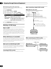
... need not connect cables to exit the menu. The i.LINK terminals on the rear of differences in connection) that can be connected using a single i.LINK cable. What can be identified. Connecting D-VHS recorders Use the i.LINK terminals when connecting D-VHS recorders. Media Receiver POWER REC DATA ON STANDBY TIMER ACQUISITION i.LINK cables D-VHS recorder D-VHS recorder 54 En When connecting a single D-VHS recorder Media Receiver (rear view) CR CONTROL IN ANTENNA/ CABLE A IN Cable CARD S-VIDEO INPUT 2 VIDEO R-AUDIO-L DIGITAL OUT OPTICAL (TS) S400 VIDEO INPUT...
... need not connect cables to exit the menu. The i.LINK terminals on the rear of differences in connection) that can be connected using a single i.LINK cable. What can be identified. Connecting D-VHS recorders Use the i.LINK terminals when connecting D-VHS recorders. Media Receiver POWER REC DATA ON STANDBY TIMER ACQUISITION i.LINK cables D-VHS recorder D-VHS recorder 54 En When connecting a single D-VHS recorder Media Receiver (rear view) CR CONTROL IN ANTENNA/ CABLE A IN Cable CARD S-VIDEO INPUT 2 VIDEO R-AUDIO-L DIGITAL OUT OPTICAL (TS) S400 VIDEO INPUT...
Owner's Manual
Page 55
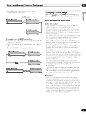
... play back digital TV programs recorded using connected D-VHS recorders, use ) or do not switch on this is the case, connect the analog output terminals on the D-VHS recorder to select i.LINK. Check the instruction manual that presents data coding and device authentication. • i.LINK may not allow copy-restricted video, audio, and other data to two D-VHS recorders that support i.LINK. Media Receiver POWER REC DATA ON STANDBY TIMER...
... play back digital TV programs recorded using connected D-VHS recorders, use ) or do not switch on this is the case, connect the analog output terminals on the D-VHS recorder to select i.LINK. Check the instruction manual that presents data coding and device authentication. • i.LINK may not allow copy-restricted video, audio, and other data to two D-VHS recorders that support i.LINK. Media Receiver POWER REC DATA ON STANDBY TIMER...

Owner's Manual
Page 57
... that mode. • With "Disable" (factory default) selected, less power is consumed when the system is the case, connect i.LINK devices. • If none of the connected equipment has been supported for control, you to change the D-VHS recorder to be operated. 6 Shows the type of inserted video tape; After pressing this button, press / to select the desired model from the list, and...
... that mode. • With "Disable" (factory default) selected, less power is consumed when the system is the case, connect i.LINK devices. • If none of the connected equipment has been supported for control, you to change the D-VHS recorder to be operated. 6 Shows the type of inserted video tape; After pressing this button, press / to select the desired model from the list, and...
Owner's Manual
Page 59
... xxxxxxxxxxxxxxxxxxxxx xxxxxxxxxxxxxxxxxxxxx Home Menu Exit • The screen for recording test appears. 6 Check that it to preset digital TV programs for recording with the supplied tape.) VCR CONTROL Position the light emitting section on the rear of the Media Receiver. Media Receiver (rear view) IN OUT VCR CONTROL CONTROL IN ANTENNA B ANTENNA/ CABLE A IN Cable CARD S-VIDEO INPUT 2 VIDEO R-AUDIO-L DIGITAL O OPTICA (TS) S400 VIDEO INPUT 1 COMPON R-AUDIO-L Y CB/ SERVICE ONLY OUT MONITOR OUT S-VIDEO VIDEO R-AUDIO-L S-VIDEO R-AUDIO-L IINNPUTT 33 Y CB...
... xxxxxxxxxxxxxxxxxxxxx xxxxxxxxxxxxxxxxxxxxx Home Menu Exit • The screen for recording test appears. 6 Check that it to preset digital TV programs for recording with the supplied tape.) VCR CONTROL Position the light emitting section on the rear of the Media Receiver. Media Receiver (rear view) IN OUT VCR CONTROL CONTROL IN ANTENNA B ANTENNA/ CABLE A IN Cable CARD S-VIDEO INPUT 2 VIDEO R-AUDIO-L DIGITAL O OPTICA (TS) S400 VIDEO INPUT 1 COMPON R-AUDIO-L Y CB/ SERVICE ONLY OUT MONITOR OUT S-VIDEO VIDEO R-AUDIO-L S-VIDEO R-AUDIO-L IINNPUTT 33 Y CB...
Owner's Manual
Page 61
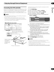
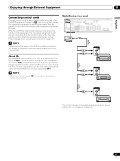
... remote control sensor on the Plasma Display when operating the connected equipment. Media Receiver (rear view) IN OUT VCR CONTROL CONTROL IN ANTENNA B ANTENNA/ CABLE A IN Cable CARD S-VIDEO INPUT 2 VIDEO R-AUDIO-L DIGITAL OUT OPTICAL (TS) S400 VIDEO INPUT 1 COMPONENT VIDEO R-AUDIO-L Y CB/PB CR/PR SERVICE ONLY OUT MONITOR OUT S-VIDEO VIDEO R-AUDIO-L S-VIDEO R-AUDIO-L IINNPUTT 33 Y CB/PB CR/PR INPUT 1 INPUT 3 HDMI IN OUT CONTROL • Make sure that came with mini plugs (no resistance). 61 En For more information, see the instruction manual that the power...
... remote control sensor on the Plasma Display when operating the connected equipment. Media Receiver (rear view) IN OUT VCR CONTROL CONTROL IN ANTENNA B ANTENNA/ CABLE A IN Cable CARD S-VIDEO INPUT 2 VIDEO R-AUDIO-L DIGITAL OUT OPTICAL (TS) S400 VIDEO INPUT 1 COMPONENT VIDEO R-AUDIO-L Y CB/PB CR/PR SERVICE ONLY OUT MONITOR OUT S-VIDEO VIDEO R-AUDIO-L S-VIDEO R-AUDIO-L IINNPUTT 33 Y CB/PB CR/PR INPUT 1 INPUT 3 HDMI IN OUT CONTROL • Make sure that came with mini plugs (no resistance). 61 En For more information, see the instruction manual that the power...
Owner's Manual
Page 69
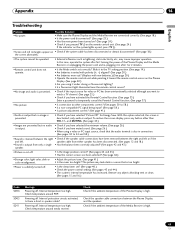
...-compatible PC signal being input? (See page 58.) • Is picture adjustment correct? (See page 41.) • Audio is output but no image is presented. • Check if you pressed TV on the remote control unit. (See page 24.) If the indicator on the system lights up red, press TV . • Green and red rectangles appear on the Plasma Display. (See page 20.) • Are you using a video...
...-compatible PC signal being input? (See page 58.) • Is picture adjustment correct? (See page 41.) • Audio is output but no image is presented. • Check if you pressed TV on the remote control unit. (See page 24.) If the indicator on the system lights up red, press TV . • Green and red rectangles appear on the Plasma Display. (See page 20.) • Are you using a video...


