Service Manual
Page 44
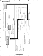
...Left + Rear speaker ≠ White White/black Green Green/black Gray Gray/black Violet Violet/black + Front speaker ≠ Right + Rear speaker ≠ KEH-P2030/XM/UC 3 3 Perform these connections when using the optional amplifier. + Rear speaker ≠ + Rear speaker ≠ 4 4 With a 2 speaker ...300 mA 12 V DC). Connection Diagram 44 1 2 2 Rear output This Product Fuse Antenna jack IP-BUS input (Blue) IP-BUS cable Multi-CD player (sold separately) Blue/white To system control terminal of ignition switch position. Black (ground) To vehicle (metal) body. A B C D ...
...Left + Rear speaker ≠ White White/black Green Green/black Gray Gray/black Violet Violet/black + Front speaker ≠ Right + Rear speaker ≠ KEH-P2030/XM/UC 3 3 Perform these connections when using the optional amplifier. + Rear speaker ≠ + Rear speaker ≠ 4 4 With a 2 speaker ...300 mA 12 V DC). Connection Diagram 44 1 2 2 Rear output This Product Fuse Antenna jack IP-BUS input (Blue) IP-BUS cable Multi-CD player (sold separately) Blue/white To system control terminal of ignition switch position. Black (ground) To vehicle (metal) body. A B C D ...

