Service Manual
Page 1
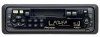
Service Manual KEH-P2030 1 2 3 4 5 6 BASS/TREBLE BOOSTER BAND KEH-P2030/XM/UC MULTI-CD CONTROL HIGH POWER CASSETTE PLAYER WITH FM/AM TUNER KEH-P2030 XM/UC KEH-P2035 XM/ES ORDER NO. CRT2980 - For the operations in Japan GENERAL INFORMATION 32 7.1 DIAGNOSIS 32 7.1.1 DISASSEMBLY 32 7.1.2 CONNECTOR FUNCTION DESCRIPTION ...33 7.2 PARTS 34 7.2.1 IC 34 7.2.2 DISPLAY 38 7.3 OPERATIONAL FLOW CHART 39 7.4 CLEANING 40 8. P.O.Box 1760, Long Beach, CA 90801-1760 U.S.A. SPECIFICATIONS 3 2. PCB CONNECTION DIAGRAM 20 4.1 TUNER AMP UNIT 20...
Service Manual KEH-P2030 1 2 3 4 5 6 BASS/TREBLE BOOSTER BAND KEH-P2030/XM/UC MULTI-CD CONTROL HIGH POWER CASSETTE PLAYER WITH FM/AM TUNER KEH-P2030 XM/UC KEH-P2035 XM/ES ORDER NO. CRT2980 - For the operations in Japan GENERAL INFORMATION 32 7.1 DIAGNOSIS 32 7.1.1 DISASSEMBLY 32 7.1.2 CONNECTOR FUNCTION DESCRIPTION ...33 7.2 PARTS 34 7.2.1 IC 34 7.2.2 DISPLAY 38 7.3 OPERATIONAL FLOW CHART 39 7.4 CLEANING 40 8. P.O.Box 1760, Long Beach, CA 90801-1760 U.S.A. SPECIFICATIONS 3 2. PCB CONNECTION DIAGRAM 20 4.1 TUNER AMP UNIT 20...
Service Manual
Page 2
... or failures that adjustments, settings or cleaning should be used in the product. E 5. F 2 KEH-P2030/XM/UC 1 2 3 4 Improperly performed repairs can maintain the product performances. Cleaning For optical pickups, tape-deck heads, lenses and mirrors used . Health & Safety Code Section 25249.6 - When you should be installed before shipping out in accordance with the procedures or instructions described in this manual, be performed to...
... or failures that adjustments, settings or cleaning should be used in the product. E 5. F 2 KEH-P2030/XM/UC 1 2 3 4 Improperly performed repairs can maintain the product performances. Cleaning For optical pickups, tape-deck heads, lenses and mirrors used . Health & Safety Code Section 25249.6 - When you should be installed before shipping out in accordance with the procedures or instructions described in this manual, be performed to...
Service Manual
Page 3
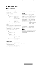
SPECIFICATIONS - KEH-P2030/XM/UC Backup current Less than 3 mA 4.76 cm/sec. (+0.14cm/sec., -0.05cm/sec.) KEH-P2030/XM/UC 5 6 7 8 A B C D E F 3 8 5 6 7 1.
SPECIFICATIONS - KEH-P2030/XM/UC Backup current Less than 3 mA 4.76 cm/sec. (+0.14cm/sec., -0.05cm/sec.) KEH-P2030/XM/UC 5 6 7 8 A B C D E F 3 8 5 6 7 1.
Service Manual
Page 6
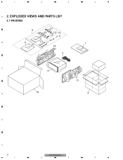
EXPLODED VIEWS AND PARTS LIST 2.1 PACKING 5 14 15 12 10 11 6 8 B 9 13 7 16 3 4 1 C 4 17 18 D 2 E F 6 KEH-P2030/XM/UC 1 2 3 4 1 2 3 A 2.
EXPLODED VIEWS AND PARTS LIST 2.1 PACKING 5 14 15 12 10 11 6 8 B 9 13 7 16 3 4 1 C 4 17 18 D 2 E F 6 KEH-P2030/XM/UC 1 2 3 4 1 2 3 A 2.
Service Manual
Page 7
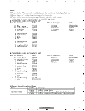
... "*" are generally unavailable because they are used for disassembly. - Description Part No. For the applying amount of no amount instructions, apply as you think it appropriate.) - PACKING(KEH-P2030) SECTION PARTS LIST Mark No. Mark No. Description Part No. 1-1 Owner's Manual 1-2 Installation Manual 2 Contain Box 3 Cord Assy 4 Polyethylene Bag CZR2955 CZR2956 CZH5596 CZD2976 CZE2903 * 5 Accessory Assy 6 Spring 7 Handle 8 Bush * 9 Polyethylene Bag CZE2955...
... "*" are generally unavailable because they are used for disassembly. - Description Part No. For the applying amount of no amount instructions, apply as you think it appropriate.) - PACKING(KEH-P2030) SECTION PARTS LIST Mark No. Mark No. Description Part No. 1-1 Owner's Manual 1-2 Installation Manual 2 Contain Box 3 Cord Assy 4 Polyethylene Bag CZR2955 CZR2956 CZH5596 CZD2976 CZE2903 * 5 Accessory Assy 6 Spring 7 Handle 8 Bush * 9 Polyethylene Bag CZE2955...
Service Manual
Page 9
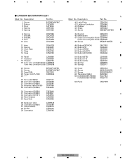
... 16 Panel CZN6866 17 Insulator CZN6836 * 18 Chassis CZN6735 19 Tuner Amp Unit(KEH-P2030) CZW5537 Tuner Amp Unit(KEH-P2035) CZW5538 20 Screw 21 Screw 22 Fuse(10A) 23 Tuner Unit(TU100) 24 BPZ26P100FZK BSZ26P100FMC CEK1208 CZW5534 25 Pin Jack(CN350) 26 Connector(CN400) 27 Connector(CN800) 28 Antenna Jack(CN100) 29 Connector(CN200) CKB1041 CKS3408 CKS3581 CKX1056 CZK2945 30 Connector(CN250) 31 Connector(CN600) 32 Connector(CN101) 33 Rear Chassis...
... 16 Panel CZN6866 17 Insulator CZN6836 * 18 Chassis CZN6735 19 Tuner Amp Unit(KEH-P2030) CZW5537 Tuner Amp Unit(KEH-P2035) CZW5538 20 Screw 21 Screw 22 Fuse(10A) 23 Tuner Unit(TU100) 24 BPZ26P100FZK BSZ26P100FMC CEK1208 CZW5534 25 Pin Jack(CN350) 26 Connector(CN400) 27 Connector(CN800) 28 Antenna Jack(CN100) 29 Connector(CN200) CKB1041 CKS3408 CKS3581 CKX1056 CZK2945 30 Connector(CN250) 31 Connector(CN600) 32 Connector(CN101) 33 Rear Chassis...
Service Manual
Page 11
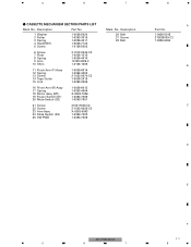
... KEH-P2030/XM/UC 11 5 6 7 8 5 6 7 8 - Description Part No. 1 Washer 2 Roller 3 Spring 4 Head(HD1) 5 Screw 1-0036-5024 1-0363-3018 1-0036-4011 1-0036-7123 1-0138-5002 6 Screw 7 Plate 8 Spring 9 Arm 10 Shim 2-1012-0040-C2 1-0036-1015 1-0036-4010 10138-2005-3 1-0138-1006 11 Pinch Arm (F) Assy 12 Spring 13 Screw 14 Tape Guide 15...16 Pinch Arm (R) Assy 17 Spring 18 Motor Assy (M1) 19 Power Switch (S1) 20 Mute Switch (S2) 1-0036-6013 1-0363-4004 X-0363-7006 1-0363-7005 1-0363-7001 21 Screw 22 Screw 23 Arm Assy 24 Slide Switch (S3) 25 SW PWB 213317040-C2 2-1032-0025-C2 X-0363-6003 ...
... KEH-P2030/XM/UC 11 5 6 7 8 5 6 7 8 - Description Part No. 1 Washer 2 Roller 3 Spring 4 Head(HD1) 5 Screw 1-0036-5024 1-0363-3018 1-0036-4011 1-0036-7123 1-0138-5002 6 Screw 7 Plate 8 Spring 9 Arm 10 Shim 2-1012-0040-C2 1-0036-1015 1-0036-4010 10138-2005-3 1-0138-1006 11 Pinch Arm (F) Assy 12 Spring 13 Screw 14 Tape Guide 15...16 Pinch Arm (R) Assy 17 Spring 18 Motor Assy (M1) 19 Power Switch (S1) 20 Mute Switch (S2) 1-0036-6013 1-0363-4004 X-0363-7006 1-0363-7005 1-0363-7001 21 Screw 22 Screw 23 Arm Assy 24 Slide Switch (S3) 25 SW PWB 213317040-C2 2-1032-0025-C2 X-0363-6003 ...
Service Manual
Page 12
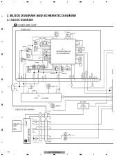
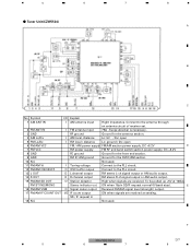
... DIAGRAM AND SCHEMATIC DIAGRAM 3.1 BLOCK DIAGRAM A TUNER AMP UNIT TUNER UNIT AM IFT3 TP1 T1 FM DET 2nd IF 450kHz 46 45 37 36 35 34 CF3 CF4 CF2 49 32 B 31 51 30 AM RF Q1 AM IFT2 52 29 53 54 IC 1 55 28 27 Q3 OSC/MIX/IF AMP/...1 20 Q102 COM9V 7 14 13 COM9V 30 29 76 PLL IC150 LC72135M 36 15 Q151 EQ-AMP CE B.U5V IC200 7 53 BA4560F 46 CASSETTE MECHANISM 5 CN200 LCH 1 1 E 3 3 S1 TAPE/TUN 8 8 7 7 C SWITCH PCB HD1 HEAD 6 6 5 5 S2 MUTE Q250 2 2 B.U14V M 1 1 MOTOR+ F M1 MOTOR ASSY CN250 Q251 12 KEH-P2030/XM/UC 1 2 3 4
... DIAGRAM AND SCHEMATIC DIAGRAM 3.1 BLOCK DIAGRAM A TUNER AMP UNIT TUNER UNIT AM IFT3 TP1 T1 FM DET 2nd IF 450kHz 46 45 37 36 35 34 CF3 CF4 CF2 49 32 B 31 51 30 AM RF Q1 AM IFT2 52 29 53 54 IC 1 55 28 27 Q3 OSC/MIX/IF AMP/...1 20 Q102 COM9V 7 14 13 COM9V 30 29 76 PLL IC150 LC72135M 36 15 Q151 EQ-AMP CE B.U5V IC200 7 53 BA4560F 46 CASSETTE MECHANISM 5 CN200 LCH 1 1 E 3 3 S1 TAPE/TUN 8 8 7 7 C SWITCH PCB HD1 HEAD 6 6 5 5 S2 MUTE Q250 2 2 B.U14V M 1 1 MOTOR+ F M1 MOTOR ASSY CN250 Q251 12 KEH-P2030/XM/UC 1 2 3 4
Service Manual
Page 13
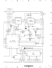
... Q400 B.U14V 22 6 20 1 GND B.U14V Q401 RESET Q500 Q602 IP-BUS 6 5 DRIVER IC2 2 PST3434UL B.U5V Q605 B.U5V 16 BU C IC400 1 Q501 Q603 HA12187FP B.U5V 12 17 61 58 60 B.U14V Q606 Q600 TX RX ASENB0 RESET 5 MUTE 5 30 ST 54 SYSPW 69 X2 Q607 Q604 IC600 1 ...SYSTEM CONTROLLER 55 B.REM 36 SW5V Q601 10 ACC 53 MOTOR 65 ASENS FFREW SWVDD 46 TAPE IN B KEYBOARD UNIT 48 39 CN800 CN900 DGND 2 7 E 8 22 XO IC900 PD6340A 23 XI Q800 B.U5V 56 VDD SW5V 36 ILLGND 81 LCD KEY MATRIX F KEH-P2030/XM/UC 13 5 6 7 8 ELECTRONIC VOLUME POWER AMP B...
... Q400 B.U14V 22 6 20 1 GND B.U14V Q401 RESET Q500 Q602 IP-BUS 6 5 DRIVER IC2 2 PST3434UL B.U5V Q605 B.U5V 16 BU C IC400 1 Q501 Q603 HA12187FP B.U5V 12 17 61 58 60 B.U14V Q606 Q600 TX RX ASENB0 RESET 5 MUTE 5 30 ST 54 SYSPW 69 X2 Q607 Q604 IC600 1 ...SYSTEM CONTROLLER 55 B.REM 36 SW5V Q601 10 ACC 53 MOTOR 65 ASENS FFREW SWVDD 46 TAPE IN B KEYBOARD UNIT 48 39 CN800 CN900 DGND 2 7 E 8 22 XO IC900 PD6340A 23 XI Q800 B.U5V 56 VDD SW5V 36 ILLGND 81 LCD KEY MATRIX F KEH-P2030/XM/UC 13 5 6 7 8 ELECTRONIC VOLUME POWER AMP B...
Service Manual
Page 14
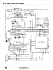
...C801 R1 C800 R1 D805 1SS133 D803 1SS133 D801 1SS133 GND3 GND1 F A 14 KEH-P2030/XM/UC 1 2 3 4 DATA CLK 1 2 3 4 3.2 OVERALL CONNECTION DIAGRAM Note: When ordering service parts, be sure to refer to "EXPLODED VIEWS AND PARTS LIST" or "ELECTRICAL PARTS LIST". Q250 2SA1706 1 1 MOTOR+ R250 14V 3R3 1/4W R252 1R8K R253 ... TUNPDI + GND5 GND2 MUTE TUNPCE TUNPCK TUNPDO TUNPDI DPDT KYDT VDT VST C R205 C207 R209 C209 3 3 AGND 2 2 RCH 1 1 LCH C201 22P C203 R001 R201 47K R203 100 C210 33 4 100/10 C205 3 100P 2 15K R207 560K 1 R01 R211 1K EQ-AMP GND IN+2 IN+1 ...
...C801 R1 C800 R1 D805 1SS133 D803 1SS133 D801 1SS133 GND3 GND1 F A 14 KEH-P2030/XM/UC 1 2 3 4 DATA CLK 1 2 3 4 3.2 OVERALL CONNECTION DIAGRAM Note: When ordering service parts, be sure to refer to "EXPLODED VIEWS AND PARTS LIST" or "ELECTRICAL PARTS LIST". Q250 2SA1706 1 1 MOTOR+ R250 14V 3R3 1/4W R252 1R8K R253 ... TUNPDI + GND5 GND2 MUTE TUNPCE TUNPCK TUNPDO TUNPDI DPDT KYDT VDT VST C R205 C207 R209 C209 3 3 AGND 2 2 RCH 1 1 LCH C201 22P C203 R001 R201 47K R203 100 C210 33 4 100/10 C205 3 100P 2 15K R207 560K 1 R01 R211 1K EQ-AMP GND IN+2 IN+1 ...
Service Manual
Page 15
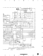
...RESET...22 55 POWER AMP C512 ...REAR OUT CN350 RCH 1 GND 3 LCH 2 GND1 FM -8dBs AM -5.5dBs TAPE-4.5dBs ← ← + + KEH-P2030/XM/UC 5 6 7 GND FRFR+ FLFL+ RL+ RLRR+ RRACC B_REM BU A B C D E F A 15 8 RL+ FL+ FR+ FR- Therefore, when replacing, be sure to use parts of the part.... RR+ RL- 5 6 7 8 C314 10P C316 10P C313 10P C315 10P VCK VDT VST 19 18 17 16 15 10 11 12 13 14 R303 100 R305 100 ELECTRONIC VOLUME...
...RESET...22 55 POWER AMP C512 ...REAR OUT CN350 RCH 1 GND 3 LCH 2 GND1 FM -8dBs AM -5.5dBs TAPE-4.5dBs ← ← + + KEH-P2030/XM/UC 5 6 7 GND FRFR+ FLFL+ RL+ RLRR+ RRACC B_REM BU A B C D E F A 15 8 RL+ FL+ FR+ FR- Therefore, when replacing, be sure to use parts of the part.... RR+ RL- 5 6 7 8 C314 10P C316 10P C313 10P C315 10P VCK VDT VST 19 18 17 16 15 10 11 12 13 14 R303 100 R305 100 ELECTRONIC VOLUME...
Service Manual
Page 18
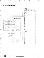
1 2 3 4 A 3.4 CASSETTE MECHANISM AA TUNER AMP UNIT B Rch C Lch HD1 HEAD 1-0036-7123 S1 TAPE/TUN D 1-0363-7005 S2 MUTE 1-0363-7001 E GND 3 Rch 2 Lch 1 CC SWITCH PCB CN200 3 2 1 Rch Lch S3 FWD/REV 1-0363-7002 M M1 MOTOR ASSY X-0363-7006 GND3 8 TAPE-IN 7 GND2 6 FF/REW 5 GND1 4 N/R 3 MOTOR- 2 MOTOR+ 1 CN250 8 7 6 5 4 3 2 1 F C 18 KEH-P2030/XM/UC 1 2 3 4
1 2 3 4 A 3.4 CASSETTE MECHANISM AA TUNER AMP UNIT B Rch C Lch HD1 HEAD 1-0036-7123 S1 TAPE/TUN D 1-0363-7005 S2 MUTE 1-0363-7001 E GND 3 Rch 2 Lch 1 CC SWITCH PCB CN200 3 2 1 Rch Lch S3 FWD/REV 1-0363-7002 M M1 MOTOR ASSY X-0363-7006 GND3 8 TAPE-IN 7 GND2 6 FF/REW 5 GND1 4 N/R 3 MOTOR- 2 MOTOR+ 1 CN250 8 7 6 5 4 3 2 1 F C 18 KEH-P2030/XM/UC 1 2 3 4
Service Manual
Page 20
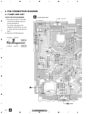
...diagrams A TUNER AMP UNIT BUS CONNECTOR CN400 CORD ASSY CN600 17 4 3 21 16 15 14 13 12 11 10 9 7 65 D604 8765 43 2 1 18 11 10 9 8 D605 D608 + C612 Connector Capacitor R610 D600 D601 L600 (ES) SIDE A P.C.Board Chip Part... CN250 L800 7531 8642 CN800 F B CN900 A 20 KEH-P2030/XM/UC 1 2 3 4 For further information for several destination. 1 2 3 4 A 4. PCB CONNECTION DIAGRAM 4.1 TUNER AMP UNIT NOTE FOR PCB DIAGRAMS 1. The parts mounted on this PCB include all necessary parts for respective destinations, be sure to check with the schematic diaB gram. 2.
...diagrams A TUNER AMP UNIT BUS CONNECTOR CN400 CORD ASSY CN600 17 4 3 21 16 15 14 13 12 11 10 9 7 65 D604 8765 43 2 1 18 11 10 9 8 D605 D608 + C612 Connector Capacitor R610 D600 D601 L600 (ES) SIDE A P.C.Board Chip Part... CN250 L800 7531 8642 CN800 F B CN900 A 20 KEH-P2030/XM/UC 1 2 3 4 For further information for several destination. 1 2 3 4 A 4. PCB CONNECTION DIAGRAM 4.1 TUNER AMP UNIT NOTE FOR PCB DIAGRAMS 1. The parts mounted on this PCB include all necessary parts for respective destinations, be sure to check with the schematic diaB gram. 2.
Service Manual
Page 26
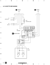
1 2 3 4 A 4.3 CASSETTE MECHANISM A CN250 A CN200 B S1 TAPE/TUN S2 MUTE 87654321 M M1 MOTOR ASSY C S3 FWD/REV S3 CC SWITCH PCB D 1 2 3 12 3 E HD1 HEAD 123 Rch Lch F C 26 KEH-P2030/XM/UC 1 2 3 4
1 2 3 4 A 4.3 CASSETTE MECHANISM A CN250 A CN200 B S1 TAPE/TUN S2 MUTE 87654321 M M1 MOTOR ASSY C S3 FWD/REV S3 CC SWITCH PCB D 1 2 3 12 3 E HD1 HEAD 123 Rch Lch F C 26 KEH-P2030/XM/UC 1 2 3 4
Service Manual
Page 32
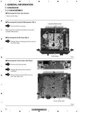
...remove the Grille Assy. 1 C 2 1 2 - Remove the Case. - Removing the Cassette Mechanism (Fig.1) 1 Remove the four screws. 1 2 3 4 7. Removing the Case (not shown) 1. Cassette Mechanism 1 1 - D 1 2 Straight the tabs at five locations indicated. 3 Remove the screw and then remove the Tuner Amp Unit. Removing the Tuner Amp Unit (Fig.2) 1 Remove the three screws. B Disconnect the connector and then remove the Cassette Mechanism . GENERAL INFORMATION 7.1 DIAGNOSIS 7.1.1 DISASSEMBLY A - E Grille Assy 1 Fig.1 1 3 2 F 32 1 2 2 2 2 Tuner Amp Unit Fig.2 KEH-P2030...
...remove the Grille Assy. 1 C 2 1 2 - Remove the Case. - Removing the Cassette Mechanism (Fig.1) 1 Remove the four screws. 1 2 3 4 7. Removing the Case (not shown) 1. Cassette Mechanism 1 1 - D 1 2 Straight the tabs at five locations indicated. 3 Remove the screw and then remove the Tuner Amp Unit. Removing the Tuner Amp Unit (Fig.2) 1 Remove the three screws. B Disconnect the connector and then remove the Cassette Mechanism . GENERAL INFORMATION 7.1 DIAGNOSIS 7.1.1 DISASSEMBLY A - E Grille Assy 1 Fig.1 1 3 2 F 32 1 2 2 2 2 Tuner Amp Unit Fig.2 KEH-P2030...
Service Manual
Page 33
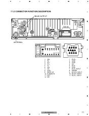
5 6 7 7.1.2 CONNECTOR FUNCTION DESCRIPTION REAR OUTPUT 8 A FUSE 10A L B R 10 10 ANTENNA 8 7 65432 1 9 10 11 12 1 RR+ 2 RL3 RL+ 4 FL+ 5 FL6 FR+ 7 FR8 GND 9 BACK UP 10 B.REMOTE 11 ACC 12 RR- 8 9 10 11 56 7 C 1234 1 BUS+ 2 GND 3 GND 4 NC 5 BUS- 6 GND D 7 BUS+ INPUT 8 ASENB 9 BUS R+ INPUT 10 BUS R- INPUT E F KEH-P2030/XM/UC 33 5 6 7 8 INPUT 11 BUS L-
5 6 7 7.1.2 CONNECTOR FUNCTION DESCRIPTION REAR OUTPUT 8 A FUSE 10A L B R 10 10 ANTENNA 8 7 65432 1 9 10 11 12 1 RR+ 2 RL3 RL+ 4 FL+ 5 FL6 FR+ 7 FR8 GND 9 BACK UP 10 B.REMOTE 11 ACC 12 RR- 8 9 10 11 56 7 C 1234 1 BUS+ 2 GND 3 GND 4 NC 5 BUS- 6 GND D 7 BUS+ INPUT 8 ASENB 9 BUS R+ INPUT 10 BUS R- INPUT E F KEH-P2030/XM/UC 33 5 6 7 8 INPUT 11 BUS L-
Service Manual
Page 34
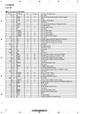
...select pin"H":AM "L":FM Tuner power supply control output Grille power supply control output(5V) Not used Tape insert sense input Not used FF/REW sense input Clock adjustment output Tape direction sense input "H":NOR "L":REV Not used Motor control output System power output B.Remote ON/OFF output Not used Slave power supply control output Power supply conrol output for IP BUS interface IC Reset input Not used Grille detach sense input Not used ACC power sense input Backup power sense input GND Power supply Crystal oscillator connection pin F 34 KEH-P2030/XM/UC 1 2 3 4 1 2 7.2 PARTS...
...select pin"H":AM "L":FM Tuner power supply control output Grille power supply control output(5V) Not used Tape insert sense input Not used FF/REW sense input Clock adjustment output Tape direction sense input "H":NOR "L":REV Not used Motor control output System power output B.Remote ON/OFF output Not used Slave power supply control output Power supply conrol output for IP BUS interface IC Reset input Not used Grille detach sense input Not used ACC power sense input Backup power sense input GND Power supply Crystal oscillator connection pin F 34 KEH-P2030/XM/UC 1 2 3 4 1 2 7.2 PARTS...
Service Manual
Page 35
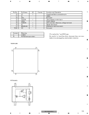
... MODELIN NC I/O Format I I I I I Format C N Meaning C MOS N Channel open drain Function and Operation A Crystal oscillator connection pin (GND) Not used Test program mode input Power supply A/D converter reference voltage terminal Signal level input Distinction input (2.0-3.0V) Not used B IC's marked by * are very liable to be damaged by electrostatic induction. *000974490 21 40 C 41 20 D 60 1 80 61 PST3434UL E F KEH-P2030/XM/UC 35 5 6 7 8 Be careful in...
... MODELIN NC I/O Format I I I I I Format C N Meaning C MOS N Channel open drain Function and Operation A Crystal oscillator connection pin (GND) Not used Test program mode input Power supply A/D converter reference voltage terminal Signal level input Distinction input (2.0-3.0V) Not used B IC's marked by * are very liable to be damaged by electrostatic induction. *000974490 21 40 C 41 20 D 60 1 80 61 PST3434UL E F KEH-P2030/XM/UC 35 5 6 7 8 Be careful in...
Service Manual
Page 37
... switch section power supply. F KEH-P2030/XM/UC 37 5 6 7 8 To be pulled up +5V at seeking. Tuner Unit(CZW5534) A B C No. Symbol I/O Explain 1 AM ANT IN I Tuning voltage Connect to the PLL circuit. 12 FM/AM OSC BUFF O OSC buffer output Connect to the antenna through an antenna circuit of receiver set. 2 FM ANT IN I FM antenna input 75Ω . Connect to the PLL circuit. 13 L OUT O L channel output FM stereo...
... switch section power supply. F KEH-P2030/XM/UC 37 5 6 7 8 To be pulled up +5V at seeking. Tuner Unit(CZW5534) A B C No. Symbol I/O Explain 1 AM ANT IN I Tuning voltage Connect to the PLL circuit. 12 FM/AM OSC BUFF O OSC buffer output Connect to the antenna through an antenna circuit of receiver set. 2 FM ANT IN I FM antenna input 75Ω . Connect to the PLL circuit. 13 L OUT O L channel output FM stereo...
Service Manual
Page 44
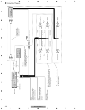
...≠ Right + Rear speaker ≠ KEH-P2030/XM/UC 3 3 Perform these connections when using the optional amplifier. + Rear speaker ≠ + Rear speaker ≠ 4 4 Connection Diagram 44 1 2 2 Rear output This Product Fuse Antenna jack IP-BUS input (Blue) IP-BUS cable Multi-CD player (sold separately) Blue/white To system control terminal of ignition switch position. Yellow To terminal always supplied with RCA pin plugs (sold separately) Power amp (sold separately) Connecting cords with power regardless of the power amp or Auto-antenna relay control terminal (max...
...≠ Right + Rear speaker ≠ KEH-P2030/XM/UC 3 3 Perform these connections when using the optional amplifier. + Rear speaker ≠ + Rear speaker ≠ 4 4 Connection Diagram 44 1 2 2 Rear output This Product Fuse Antenna jack IP-BUS input (Blue) IP-BUS cable Multi-CD player (sold separately) Blue/white To system control terminal of ignition switch position. Yellow To terminal always supplied with RCA pin plugs (sold separately) Power amp (sold separately) Connecting cords with power regardless of the power amp or Auto-antenna relay control terminal (max...


