
Other Manual
Page 2
Contents Connecting the Units 2 DFS Alarm Installation 7 Description 7 Door Switches 7 DOOR SWITCH (White/Yellow 8 ALARM OUTPUT (Brown 10 ALARM SENSOR (White/Red 11 DOOR LOCK (White/Orange 12 STARTER CUT-OFF (Blue/Brown 13 Avoiding Trouble 14 Installation 15 GM Panel Type Installation 16 GM ('94 & Newer Vehicles) Panel Type Installation 17 GM ('95 & Newer Monte Carlo, Caprice Classic, Lumina, Cavalier) Installation 18 Standard Chrysler/Dodge/ Plymouth Installation 19 '95 Cirrus/Stratus Installation 20 Grand Cherokee/Sebring/ Avenger Installation 21 1
Contents Connecting the Units 2 DFS Alarm Installation 7 Description 7 Door Switches 7 DOOR SWITCH (White/Yellow 8 ALARM OUTPUT (Brown 10 ALARM SENSOR (White/Red 11 DOOR LOCK (White/Orange 12 STARTER CUT-OFF (Blue/Brown 13 Avoiding Trouble 14 Installation 15 GM Panel Type Installation 16 GM ('94 & Newer Vehicles) Panel Type Installation 17 GM ('95 & Newer Monte Carlo, Caprice Classic, Lumina, Cavalier) Installation 18 Standard Chrysler/Dodge/ Plymouth Installation 19 '95 Cirrus/Stratus Installation 20 Grand Cherokee/Sebring/ Avenger Installation 21 1
Other Manual
Page 3
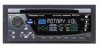
... with insulating tape. Likewise, do , the protection circuit may result in the electrical system, be sure to disconnect the ≠ battery cable before beginning installation. • Refer to the owner's manual for details on the fuse holder. • Since a unique BPTL circuit is employed, never wire so the... ON, a control signal is output through a hole into the lead. If the insulation of the wiring melts or gets torn, there is installed in places that get hot, such as the gear shift, handbrake and seat rails. This will not be drained when you do not connect the...
... with insulating tape. Likewise, do , the protection circuit may result in the electrical system, be sure to disconnect the ≠ battery cable before beginning installation. • Refer to the owner's manual for details on the fuse holder. • Since a unique BPTL circuit is employed, never wire so the... ON, a control signal is output through a hole into the lead. If the insulation of the wiring melts or gets torn, there is installed in places that get hot, such as the gear shift, handbrake and seat rails. This will not be drained when you do not connect the...
Other Manual
Page 4
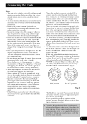
...) Multi-CD player (sold separately) To vehicle (metal) body. Rear output Caution: Connect the supplied connector without fail. Orange To electric terminal controlled by ignition switch (12 V DC) ON/OFF. Yellow/black With a 2 speaker system, connect to a Subwoofer Blue/Brown White/Orange White/Red Brown White/Yellow See the section "DFS Alarm Installation...
...) Multi-CD player (sold separately) To vehicle (metal) body. Rear output Caution: Connect the supplied connector without fail. Orange To electric terminal controlled by ignition switch (12 V DC) ON/OFF. Yellow/black With a 2 speaker system, connect to a Subwoofer Blue/Brown White/Orange White/Red Brown White/Yellow See the section "DFS Alarm Installation...
Other Manual
Page 6
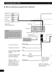
...) To vehicle (metal) body. Rear output This product Antenna jack Front output IP-BUS input (Blue) Multi-CD player (sold separately) Blue/Brown White/Orange White/Red Brown White/Yellow See the section "DFS Alarm Installation". To terminal always supplied with power regardless of any connections. Black (ground) To lighting switch terminal. Yellow...
...) To vehicle (metal) body. Rear output This product Antenna jack Front output IP-BUS input (Blue) Multi-CD player (sold separately) Blue/Brown White/Orange White/Red Brown White/Yellow See the section "DFS Alarm Installation". To terminal always supplied with power regardless of any connections. Black (ground) To lighting switch terminal. Yellow...
Other Manual
Page 8
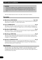
... • Because of the complexity of today's technically advanced vehicle wiring systems, we recommend that your DFS Alarm be installed ONLY by a professional Pioneer installer. • Install the unit so that it can be quickly disconnected in case the engine doesn't start even if the unit operates correctly. (Refer to "STARTER CUT-...
... • Because of the complexity of today's technically advanced vehicle wiring systems, we recommend that your DFS Alarm be installed ONLY by a professional Pioneer installer. • Install the unit so that it can be quickly disconnected in case the engine doesn't start even if the unit operates correctly. (Refer to "STARTER CUT-...
Other Manual
Page 10
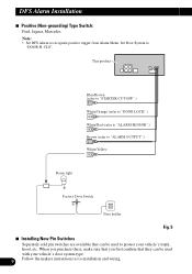
...STARTER CUT-OFF".) White/Orange (refer to "DOOR LOCK".) White/Red (refer to "ALARM SENSOR".) Brown (refer to installation and wiring. Set Door System to recognize positive trigger from Alarm Menu. DFS Alarm Installation 7 Positive (Non-grounding) Type Switch: Ford, Jaguar, Mercedes Note: • Set DFS Alarm to "DOOR-H :... door system type. 9 Follow the makers instructions as to "ALARM OUTPUT".) White/Yellow Dome light Factory Door Switch Fuse holder Fig. 5 7 Installing New Pin Switches Separately sold pin switches are available that can be used with your vehicle's trunk, hood, etc.
...STARTER CUT-OFF".) White/Orange (refer to "DOOR LOCK".) White/Red (refer to "ALARM SENSOR".) Brown (refer to installation and wiring. Set Door System to recognize positive trigger from Alarm Menu. DFS Alarm Installation 7 Positive (Non-grounding) Type Switch: Ford, Jaguar, Mercedes Note: • Set DFS Alarm to "DOOR-H :... door system type. 9 Follow the makers instructions as to "ALARM OUTPUT".) White/Yellow Dome light Factory Door Switch Fuse holder Fig. 5 7 Installing New Pin Switches Separately sold pin switches are available that can be used with your vehicle's trunk, hood, etc.
Other Manual
Page 12
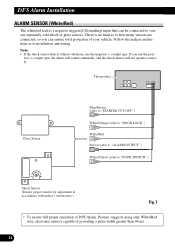
DFS Alarm Installation ALARM SENSOR (White/Red) The white/red lead is no limit as to how many sensors are connected, so you use the negative (-) output type. ... adjustment in accordance with maker's instructions.) Fig. 7 • To ensure full proper operation of DFS Alarm, Pioneer suggests using only White/Red wire, electronic sensors capable of your vehicle. Follow the makers instructions as to installation and wiring. There is a negative triggered (Grounding) input that can ensure total protection of providing a pulse...
DFS Alarm Installation ALARM SENSOR (White/Red) The white/red lead is no limit as to how many sensors are connected, so you use the negative (-) output type. ... adjustment in accordance with maker's instructions.) Fig. 7 • To ensure full proper operation of DFS Alarm, Pioneer suggests using only White/Red wire, electronic sensors capable of your vehicle. Follow the makers instructions as to installation and wiring. There is a negative triggered (Grounding) input that can ensure total protection of providing a pulse...
Other Manual
Page 13
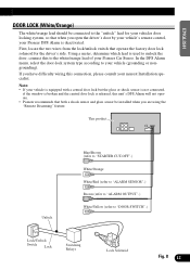
... your vehicle (grounding or nongrounding). If you have difficulty wiring this to your nearest Installation specialist. Using a meter, determine which lead is released, this unit's DFS Alarm will not operate. • Pioneer recommends that both a shock sensor and glass sensor be connected to unlock the door...; ENGLISH ESPAÑOL DOOR LOCK (White/Orange) The white/orange lead should be installed when you are using the "Remote Disarming" feature....
... your vehicle (grounding or nongrounding). If you have difficulty wiring this to your nearest Installation specialist. Using a meter, determine which lead is released, this unit's DFS Alarm will not operate. • Pioneer recommends that both a shock sensor and glass sensor be connected to unlock the door...; ENGLISH ESPAÑOL DOOR LOCK (White/Orange) The white/orange lead should be installed when you are using the "Remote Disarming" feature....
Other Manual
Page 14
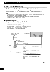
DFS Alarm Installation STARTER CUT-OFF (Blue/Brown) The blue/brown lead will provide a continuous +12 V output while alarm is sounding and for the "DFS Alarm" to operate ...
DFS Alarm Installation STARTER CUT-OFF (Blue/Brown) The blue/brown lead will provide a continuous +12 V output while alarm is sounding and for the "DFS Alarm" to operate ...
Other Manual
Page 15
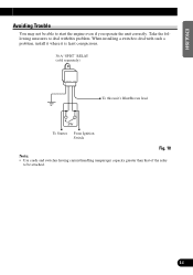
Take the following measures to deal with such a problem, install it where it is least conspicuous. 30 A "SPDT" RELAY (sold separately) To this problem. ENGLISH ESPAÑOL DEUTSCH Avoiding Trouble You may not be attached. 14 FRANÇAIS ITALIANO NEDERLANDS When installing a switch to start the engine even if you operate the unit correctly. SW To Starter From Ignition Switch Fig. 10 Note: • Use cords and switches having current handling (amperage) capacity greater than that of the relay to be able to deal with this unit's Blue/Brown lead.
Take the following measures to deal with such a problem, install it where it is least conspicuous. 30 A "SPDT" RELAY (sold separately) To this problem. ENGLISH ESPAÑOL DEUTSCH Avoiding Trouble You may not be attached. 14 FRANÇAIS ITALIANO NEDERLANDS When installing a switch to start the engine even if you operate the unit correctly. SW To Starter From Ignition Switch Fig. 10 Note: • Use cords and switches having current handling (amperage) capacity greater than that of the relay to be able to deal with this unit's Blue/Brown lead.
Other Manual
Page 16
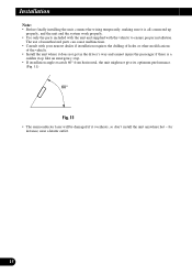
... the drilling of holes or other modifications of unauthorized parts can cause malfunctions. • Consult with the vehicle to ensure proper installation. The use of the vehicle. • Install the unit where it does not get in the driver's way and cannot injure the passenger if there is a sudden stop,... like an emergency stop. • If installation angle exceeds 60° from horizontal, the unit might not give its optimum performance. (Fig. 11) 60° Fig. 11 • The semiconductor ...
... the drilling of holes or other modifications of unauthorized parts can cause malfunctions. • Consult with the vehicle to ensure proper installation. The use of the vehicle. • Install the unit where it does not get in the driver's way and cannot injure the passenger if there is a sudden stop,... like an emergency stop. • If installation angle exceeds 60° from horizontal, the unit might not give its optimum performance. (Fig. 11) 60° Fig. 11 • The semiconductor ...

Other Manual
Page 17
ENGLISH ESPAÑOL GM Panel Type Installation An example is shown in the same way that it was fitted to the unit in Fig. 12. Sub dash 1 2 Quickie bolt slot Tube spacer Vehicle supplied bracket (not included) Quickie bolt Hex nut (5 mm) Vehicle supplied screw (not included) Bracket (not included) In some cases, this may not be provided on the vehicle to the original car stereo. Dash panel Fig. 12 DEUTSCH FRANÇAIS ITALIANO NEDERLANDS 16 Fit the bracket provided on the vehicle.
ENGLISH ESPAÑOL GM Panel Type Installation An example is shown in the same way that it was fitted to the unit in Fig. 12. Sub dash 1 2 Quickie bolt slot Tube spacer Vehicle supplied bracket (not included) Quickie bolt Hex nut (5 mm) Vehicle supplied screw (not included) Bracket (not included) In some cases, this may not be provided on the vehicle to the original car stereo. Dash panel Fig. 12 DEUTSCH FRANÇAIS ITALIANO NEDERLANDS 16 Fit the bracket provided on the vehicle.

Other Manual
Page 18
Dash panel Fig. 13 17 Installation GM ('94 & Newer Vehicles) Panel Type Installation An example is shown in the same way that it was fitted to the original car stereo. Fit the bracket provided on the vehicule. Sub dash Bracket (L) 1 2 Quickie bolt slot Tube spacer Bracket (R) Hex nut (5 mm) Quickie bolt Vehicle supplied screw (not included) Bracket (not included) In some cases, this may not be provided on the vehicle to the unit in Fig. 13.
Dash panel Fig. 13 17 Installation GM ('94 & Newer Vehicles) Panel Type Installation An example is shown in the same way that it was fitted to the original car stereo. Fit the bracket provided on the vehicule. Sub dash Bracket (L) 1 2 Quickie bolt slot Tube spacer Bracket (R) Hex nut (5 mm) Quickie bolt Vehicle supplied screw (not included) Bracket (not included) In some cases, this may not be provided on the vehicle to the unit in Fig. 13.

Other Manual
Page 19
Sub dash Screw (3 × 5 mm) Bracket Vehicle supplied screw (not included) Dash panel Fig. 14 DEUTSCH FRANÇAIS ITALIANO NEDERLANDS 18 ENGLISH ESPAÑOL GM ('95 & Newer Monte Carlo, Caprice Classic, Lumina, Cavalier) Installation An example is shown in the same way that it was fitted to the unit in Fig. 14. Fit the bracket provided on the vehicle to the original car stereo.
Sub dash Screw (3 × 5 mm) Bracket Vehicle supplied screw (not included) Dash panel Fig. 14 DEUTSCH FRANÇAIS ITALIANO NEDERLANDS 18 ENGLISH ESPAÑOL GM ('95 & Newer Monte Carlo, Caprice Classic, Lumina, Cavalier) Installation An example is shown in the same way that it was fitted to the unit in Fig. 14. Fit the bracket provided on the vehicle to the original car stereo.
Other Manual
Page 20
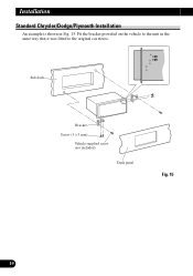
Installation Standard Chrysler/Dodge/Plymouth Installation An example is shown in the same way that it was fitted to the unit in Fig. 15. Sub dash Bracket Screw (3 × 5 mm) Vehicle supplied screw (not included) Dash panel Fig. 15 19 Fit the bracket provided on the vehicle to the original car stereo.
Installation Standard Chrysler/Dodge/Plymouth Installation An example is shown in the same way that it was fitted to the unit in Fig. 15. Sub dash Bracket Screw (3 × 5 mm) Vehicle supplied screw (not included) Dash panel Fig. 15 19 Fit the bracket provided on the vehicle to the original car stereo.

Other Manual
Page 21
Fit the bracket provided on the vehicle to the unit in Fig. 16. Sub dash Screw (3 × 5 mm) Bracket Vehicle supplied screw (not included) Dash panel Fig. 16 FRANÇAIS ITALIANO NEDERLANDS 20 ENGLISH ESPAÑOL DEUTSCH '95 Cirrus/Stratus Installation An example is shown in the same way that it was fitted to the original car stereo.
Fit the bracket provided on the vehicle to the unit in Fig. 16. Sub dash Screw (3 × 5 mm) Bracket Vehicle supplied screw (not included) Dash panel Fig. 16 FRANÇAIS ITALIANO NEDERLANDS 20 ENGLISH ESPAÑOL DEUTSCH '95 Cirrus/Stratus Installation An example is shown in the same way that it was fitted to the original car stereo.

Other Manual
Page 22
Sub dash Bracket Screw (3 × 5 mm) Vehicle supplied screw (not included) Dash panel Fig. 17 21 Fit the bracket provided on the vehicle to the original car stereo. Installation Grand Cherokee/Sebring/Avenger Installation An example is shown in the same way that it was fitted to the unit in Fig. 17.
Sub dash Bracket Screw (3 × 5 mm) Vehicle supplied screw (not included) Dash panel Fig. 17 21 Fit the bracket provided on the vehicle to the original car stereo. Installation Grand Cherokee/Sebring/Avenger Installation An example is shown in the same way that it was fitted to the unit in Fig. 17.


