Service Manual
Page 2
... SD-Board 20 7.11. Remove the C2-Board 22 7.17. A-Board (2/15) Schematic Diagram 49 11.8. A-Board (7/15) Schematic Diagram 54 11.13. A-Board (11/15) Schematic Diagram 58 11.17. SC-Board (2/4) Schematic Diagram 70 11.29. P(P-1)-Board 75 12.2. C1-Board 83 12.6. SS-Board 89...Disassembly and Assembly Instructions 18 7.1. Remove the C1-Board 22 7.16. Remove the Plasma panel section from the Cabinet assy (glass 22 7.19. A-Board (6/15) Schematic Diagram 53 11.12. A-Board (14/15) Schematic Diagram 61 11.20. SC-Board (1/4) Schematic Diagram 69 11.28. TABLE OF ...
... SD-Board 20 7.11. Remove the C2-Board 22 7.17. A-Board (2/15) Schematic Diagram 49 11.8. A-Board (7/15) Schematic Diagram 54 11.13. A-Board (11/15) Schematic Diagram 58 11.17. SC-Board (2/4) Schematic Diagram 70 11.29. P(P-1)-Board 75 12.2. C1-Board 83 12.6. SS-Board 89...Disassembly and Assembly Instructions 18 7.1. Remove the C1-Board 22 7.16. Remove the Plasma panel section from the Cabinet assy (glass 22 7.19. A-Board (6/15) Schematic Diagram 53 11.12. A-Board (14/15) Schematic Diagram 61 11.20. SC-Board (1/4) Schematic Diagram 69 11.28. TABLE OF ...

Service Manual
Page 6
... Switch, PC Digital Signal Processor, SYSTEM MPU, HDMI Switch Seine 3LV Format Converter, Plasma AI, Sub-Field Processor K Remote receiver, Power LED, C.A.T.S sensor S Power Switch GK Key Switch Board Name C1 C2 C3 SC SS SS2 SU SD Function Data Driver (Lower Right) Data Driver (Lower Center) Data... Driver (Lower Left) Scan Drive Sustain Drive Sustain out (Lower) Scan out (Upper) Non-serviceable. Scan out (Lower) Non-serviceable. SD-Board should be exchanged for...
... Switch, PC Digital Signal Processor, SYSTEM MPU, HDMI Switch Seine 3LV Format Converter, Plasma AI, Sub-Field Processor K Remote receiver, Power LED, C.A.T.S sensor S Power Switch GK Key Switch Board Name C1 C2 C3 SC SS SS2 SU SD Function Data Driver (Lower Right) Data Driver (Lower Center) Data... Driver (Lower Left) Scan Drive Sustain Drive Sustain out (Lower) Scan out (Upper) Non-serviceable. Scan out (Lower) Non-serviceable. SD-Board should be exchanged for...

Service Manual
Page 20
... connector (SC41-SU41). 3. and 7.10.) 2. Remove the flexible cables (SD1B, SD2B, SD3B, SD4B and SD5B) connected to the SD-Board. 3. Remove the screws (×7 ) and remove the SC-Board. 7.10. Remove the SC-Board 1. Remove the molding prop (×1 ). 5. Remove the SU-Board and SD-Board. (See section 7.9. Remove the screws (×2 , ×2 ) and remove the SU-
... connector (SC41-SU41). 3. and 7.10.) 2. Remove the flexible cables (SD1B, SD2B, SD3B, SD4B and SD5B) connected to the SD-Board. 3. Remove the screws (×7 ) and remove the SC-Board. 7.10. Remove the SC-Board 1. Remove the molding prop (×1 ). 5. Remove the SU-Board and SD-Board. (See section 7.9. Remove the screws (×2 , ×2 ) and remove the SU-
Service Manual
Page 26
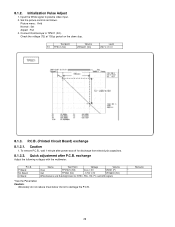
... after P.C.B. P.C.B. Caution: Absolutely do not reduce Vsus below Ve not to plasma video input. 2. exchange Adjust the following voltages with the multimeter. P Board SC Board A Board Name Test Point Voltage Volume Vsus TPVSUS (SS) Vsus ± 2V VR251 (P) * Vad TPVAD (SC) - 175V ± 2V VR16600 (SC) White balance and Sub brightness for discharge from electrolysis capacitors. 8.1.3.2. Initialization...
... after P.C.B. P.C.B. Caution: Absolutely do not reduce Vsus below Ve not to plasma video input. 2. exchange Adjust the following voltages with the multimeter. P Board SC Board A Board Name Test Point Voltage Volume Vsus TPVSUS (SS) Vsus ± 2V VR251 (P) * Vad TPVAD (SC) - 175V ± 2V VR16600 (SC) White balance and Sub brightness for discharge from electrolysis capacitors. 8.1.3.2. Initialization...

Service Manual
Page 58
... TP9006 FL9806 F1J1E104A148 G G P5V C9845 16V 0.1u TP9199 R9145 100 TP9205 R9120 100 TP9206 R9115 100 TP9207 PANEL_MAIN_ON SOS4_PS VDATA_DET STB5V_M C9846 16V 0.1u TO SC-BOARD (SC20) A33 SIDE P5V 1 SIU 2 CLK 3 GND 4 CERS 5 CRC2 6 GND 7 OC2 8 CRC1 9 SC_FPGANRST 10 OC1 11 CIS 12 GND 13 SOS6_SC1 14 SOS7_SC2 15 ...41 S OSCXI 42 IVDD 43 P64_SBI1 44 P63_SBT1 45 NBOOT_(N.C.) 46 NRST 47 48 P3.3V 49 50 R9203 22k 51 52 53 TRCST_(UND) 54 TRCD0_(UND) 55 TRCD1_(UND) 56 TRCD2_(UND) 57 TRCD3_(UND) 58 P80_ADIN0 59 P81_ADIN1 60 P82_ADIN2 61 P83_ADIN3 62 IVDD 63 VSS 64 P84_ADIN4...
... TP9006 FL9806 F1J1E104A148 G G P5V C9845 16V 0.1u TP9199 R9145 100 TP9205 R9120 100 TP9206 R9115 100 TP9207 PANEL_MAIN_ON SOS4_PS VDATA_DET STB5V_M C9846 16V 0.1u TO SC-BOARD (SC20) A33 SIDE P5V 1 SIU 2 CLK 3 GND 4 CERS 5 CRC2 6 GND 7 OC2 8 CRC1 9 SC_FPGANRST 10 OC1 11 CIS 12 GND 13 SOS6_SC1 14 SOS7_SC2 15 ...41 S OSCXI 42 IVDD 43 P64_SBI1 44 P63_SBT1 45 NBOOT_(N.C.) 46 NRST 47 48 P3.3V 49 50 R9203 22k 51 52 53 TRCST_(UND) 54 TRCD0_(UND) 55 TRCD1_(UND) 56 TRCD2_(UND) 57 TRCD3_(UND) 58 P80_ADIN0 59 P81_ADIN1 60 P82_ADIN2 61 P83_ADIN3 62 IVDD 63 VSS 64 P84_ADIN4...

Service Manual
Page 69
SC-Board (1/4) Schematic Diagram ! SC-BOARD TXNSC1ECUU (1/4) A B TO P-BOARD (P2) SC2 1 VSUS 3 GND TP1 TP2 TP4 TP5 *C16412 220V 300u *C16413 250V 1.5u VSUS *C16415 220V 300u *C16419 220V 300u + + + + C D E F 1 TO A-BOARD (A33) SC20 TERM P5V SIU TP24 CLK GND CERS SEL GND OC2 CRC1 SC_FPGANRST OC1 CIS GND SOS6 SOS7 GND UHZ CPH2 GND CEL TP25...
SC-Board (1/4) Schematic Diagram ! SC-BOARD TXNSC1ECUU (1/4) A B TO P-BOARD (P2) SC2 1 VSUS 3 GND TP1 TP2 TP4 TP5 *C16412 220V 300u *C16413 250V 1.5u VSUS *C16415 220V 300u *C16419 220V 300u + + + + C D E F 1 TO A-BOARD (A33) SC20 TERM P5V SIU TP24 CLK GND CERS SEL GND OC2 CRC1 SC_FPGANRST OC1 CIS GND SOS6 SOS7 GND UHZ CPH2 GND CEL TP25...

Service Manual
Page 72
... 22 R16722 22 R16723 22 AA_SIU AA_OC2 AA_CLK AA_OC1 *D16871 MAZ81500ML R16783 150k D16875 MA2J11100L R16755 12k R16750 12k R16756 12k R16775 4.7k ERROR DET(54) -46 SC-Board (4/4) Schematic Diagram 21 + + + + VSUS:190V TPVSUS TP64 VSET:290V VSET 22 TPVSET VSUS 23 R16713 100k IC16788 MIP3900MSSCF Q16874 B1CBGD000001 LS 4 L16699 G0C471KA0167 VSET...
... 22 R16722 22 R16723 22 AA_SIU AA_OC2 AA_CLK AA_OC1 *D16871 MAZ81500ML R16783 150k D16875 MA2J11100L R16755 12k R16750 12k R16756 12k R16775 4.7k ERROR DET(54) -46 SC-Board (4/4) Schematic Diagram 21 + + + + VSUS:190V TPVSUS TP64 VSET:290V VSET 22 TPVSET VSUS 23 R16713 100k IC16788 MIP3900MSSCF Q16874 B1CBGD000001 LS 4 L16699 G0C471KA0167 VSET...


