Service Manual
Page 2
... the A-Board 19 7.6. Remove the SS-Board 21 7.14. Remove the C1-Board 22 7.16. Remove the K-Board 23 7.21. Replace the plasma panel 24 8 Measurements and Adjustments 25 8.1. Wiring (5 41 11 Schematic Diagram 43 11.1. P(P-1)-Board (2/2) Schematic Diagram 45 11.4. A-Board (12...unit 19 7.8. Adjustment 28 9 Block Diagram 31 9.1. Wiring (2 38 PAGE 10.4. A-Board (7/15) Schematic Diagram 54 11.13. C2-Board (2/2) Schematic Diagram 66 11.25. GK, K, S and SS2-Board 79 12.4. Local screen failure 17 7 Disassembly and Assembly Instructions 18 7.1. Main Block...
... the A-Board 19 7.6. Remove the SS-Board 21 7.14. Remove the C1-Board 22 7.16. Remove the K-Board 23 7.21. Replace the plasma panel 24 8 Measurements and Adjustments 25 8.1. Wiring (5 41 11 Schematic Diagram 43 11.1. P(P-1)-Board (2/2) Schematic Diagram 45 11.4. A-Board (12...unit 19 7.8. Adjustment 28 9 Block Diagram 31 9.1. Wiring (2 38 PAGE 10.4. A-Board (7/15) Schematic Diagram 54 11.13. C2-Board (2/2) Schematic Diagram 66 11.25. GK, K, S and SS2-Board 79 12.4. Local screen failure 17 7 Disassembly and Assembly Instructions 18 7.1. Main Block...

Service Manual
Page 5
... the back of the Pb free solder on the pins or solder area before applying Pb solder. • After applying PbF solder to double layered boards, please check the component side for excess solder which may be used. This product uses Sn+Ag+Cu (tin, silver, copper) solder. 2.2. About lead free...
... the back of the Pb free solder on the pins or solder area before applying Pb solder. • After applying PbF solder to double layered boards, please check the component side for excess solder which may be used. This product uses Sn+Ag+Cu (tin, silver, copper) solder. 2.2. About lead free...

Service Manual
Page 6
..., AV Switch, PC Digital Signal Processor, SYSTEM MPU, HDMI Switch Seine 3LV Format Converter, Plasma AI, Sub-Field Processor K Remote receiver, Power LED, C.A.T.S sensor S Power Switch GK Key Switch Board Name C1 C2 C3 SC SS SS2 SU SD Function Data Driver (Lower Right) Data Driver... (Lower Center) Data Driver (Lower Left) Scan Drive Sustain Drive Sustain out (Lower) Scan out (Upper) Non-serviceable. 3 Service Navigation 3.1. SU-Board should be exchanged for service...
..., AV Switch, PC Digital Signal Processor, SYSTEM MPU, HDMI Switch Seine 3LV Format Converter, Plasma AI, Sub-Field Processor K Remote receiver, Power LED, C.A.T.S sensor S Power Switch GK Key Switch Board Name C1 C2 C3 SC SS SS2 SU SD Function Data Driver (Lower Right) Data Driver... (Lower Center) Data Driver (Lower Left) Scan Drive Sustain Drive Sustain out (Lower) Scan out (Upper) Non-serviceable. 3 Service Navigation 3.1. SU-Board should be exchanged for service...

Service Manual
Page 18
... cover 1. Disconnect the connectors (P51-P52, P53-P54, P55-P56 and P57-P58). 3. Remove the screws (×6 ) and remove the P(P-2)-Board. 3. Remove the Rear terminal cover. 7.4. Disconnect the flexible cables (A31, A32 and A33). 4. Remove the claw (×1 ). 2. Disconnect...P7, P9, P11, P25 and P35). 4. Remove the screws (×9 ) and remove the P(P-1)-Board. 5. Unlock the cable clampers to free the cable. 2. Remove the Adjustment cover. 4. Remove the P-Board Caution: To remove P.C.B. wait 1 minute after power was off for discharge from electrolysis capacitors. 1....
... cover 1. Disconnect the connectors (P51-P52, P53-P54, P55-P56 and P57-P58). 3. Remove the screws (×6 ) and remove the P(P-2)-Board. 3. Remove the Rear terminal cover. 7.4. Disconnect the flexible cables (A31, A32 and A33). 4. Remove the claw (×1 ). 2. Disconnect...P7, P9, P11, P25 and P35). 4. Remove the screws (×9 ) and remove the P(P-1)-Board. 5. Unlock the cable clampers to free the cable. 2. Remove the Adjustment cover. 4. Remove the P-Board Caution: To remove P.C.B. wait 1 minute after power was off for discharge from electrolysis capacitors. 1....

Service Manual
Page 19
... section 7.4.) 5. Remove the Tuner unit. (See section 7.4.) 2. Remove the screws (×4 ) and remove the A-Board. 7.7. Remove the screws (×2 ). 3. Disconnect the relay connector. 3. Remove the GK-Board 1. Remove the Control button unit. (See section 7.7.) 2. Disconnect the connector (GK1). 6. Remove the screws (×... to free the cable. 2. Remove the screws (×2 ) and remove the Speaker L. 7.8. 7.5. metal. 4. Remove the A-Board 1. Remove the Control button unit 1. Remove the claw (×3 ). 5. Remove the screws (×2 ) and remove the Speaker R. 4.
... section 7.4.) 5. Remove the Tuner unit. (See section 7.4.) 2. Remove the screws (×4 ) and remove the A-Board. 7.7. Remove the screws (×2 ). 3. Disconnect the relay connector. 3. Remove the GK-Board 1. Remove the Control button unit. (See section 7.7.) 2. Disconnect the connector (GK1). 6. Remove the screws (×... to free the cable. 2. Remove the screws (×2 ) and remove the Speaker L. 7.8. 7.5. metal. 4. Remove the A-Board 1. Remove the Control button unit 1. Remove the claw (×3 ). 5. Remove the screws (×2 ) and remove the Speaker R. 4.

Service Manual
Page 20
... 4. Remove the flexible cables (SU1B, SU2B, SU3B, SU4B and SU5B) connected to free the cable. 3. and 7.10.) 2. Remove the SD-Board 1. Remove the molding prop (×1 ). 5. Remove the flexible cable (SU11-SD11) and the bridge connector (SC41-SU41). 3. Remove the SC... the screws (×2 , ×2 ) and remove the SD- Remove the SU-Board and SD-Board. (See section 7.9. Unlock the cable clampers to the SU-Board. 2. Remove the SU-Board 1. Remove the screws (×7 ) and remove the SC-Board. 7.10. 7.9. Disconnect the connector (SC2). 4. Remove the flexible cables (SD1B, SD2B, ...
... 4. Remove the flexible cables (SU1B, SU2B, SU3B, SU4B and SU5B) connected to free the cable. 3. and 7.10.) 2. Remove the SD-Board 1. Remove the molding prop (×1 ). 5. Remove the flexible cable (SU11-SD11) and the bridge connector (SC41-SU41). 3. Remove the SC... the screws (×2 , ×2 ) and remove the SD- Remove the SU-Board and SD-Board. (See section 7.9. Unlock the cable clampers to the SU-Board. 2. Remove the SU-Board 1. Remove the screws (×7 ) and remove the SC-Board. 7.10. 7.9. Disconnect the connector (SC2). 4. Remove the flexible cables (SD1B, SD2B, ...

Service Manual
Page 21
... servicing stand and lay on a flat surface such as a table (covered by a soft cloth) with the Plasma panel surface facing downward. 2. Remove the SS-Board 1. Remove the screws (×7 ) and remove the SS-Board. 3. Remove the Tuner unit. (See section 7.4.) 2. Disconnect the flexible cables (SS53, SS55 and SS56).... the Tuner unit. (See section 7.4.) 2. Unlock the cable clampers to free the cable. 3. Disconnect the connectors (SS11 and SS33). 4. Remove the SS2-Board 1. Remove the screws (×2 ) and remove the SS2-Board. 7.14. Remove the Hanger metals and the Stand brackets 1.
... servicing stand and lay on a flat surface such as a table (covered by a soft cloth) with the Plasma panel surface facing downward. 2. Remove the SS-Board 1. Remove the screws (×7 ) and remove the SS-Board. 3. Remove the Tuner unit. (See section 7.4.) 2. Disconnect the flexible cables (SS53, SS55 and SS56).... the Tuner unit. (See section 7.4.) 2. Unlock the cable clampers to free the cable. 3. Disconnect the connectors (SS11 and SS33). 4. Remove the SS2-Board 1. Remove the screws (×2 ) and remove the SS2-Board. 7.14. Remove the Hanger metals and the Stand brackets 1.
Service Manual
Page 22
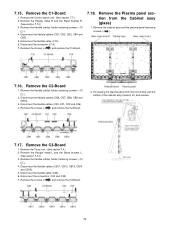
...CB8, CB9 and CB10). 3. Remove the screws (×5 ) and remove the C3-Board. 22 7.15. Remove the flexible cables holder fastening screws (×10 ). 4. Disconnect the connector (C14). 7. Remove the Plasma panel section from the front frame, pull the bottom of the cabinet assy forward, ...lift, and remove. 7.17. For leaving the plasma panel from the Cabinet assy (glass) 1. Disconnect the connectors (C33 and C35). 7. Remove the cabinet assy and the plasma panel fastening screws (×2 ). 7.16. Remove the C1-Board 1. Remove the flexible cables holder fastening screws (×10...
...CB8, CB9 and CB10). 3. Remove the screws (×5 ) and remove the C3-Board. 22 7.15. Remove the flexible cables holder fastening screws (×10 ). 4. Disconnect the connector (C14). 7. Remove the Plasma panel section from the front frame, pull the bottom of the cabinet assy forward, ...lift, and remove. 7.17. For leaving the plasma panel from the Cabinet assy (glass) 1. Disconnect the connectors (C33 and C35). 7. Remove the cabinet assy and the plasma panel fastening screws (×2 ). 7.16. Remove the C1-Board 1. Remove the flexible cables holder fastening screws (×10...

Service Manual
Page 23
... holder top front. 8. Remove the screws (×2 ) and remove the S-Board unit. 23 Remove the screw (×1 ) and remove the S-Board. 7.19. Remove the Cabinet assy. (See section 7.18.) 2. Remove the S-Board shield case. 7.20. Remove the screws (×9 ). 7. Remove the S-Board 1. Remove the S-Board. (See section 7.19.) 3. Remove the screws (×7 ). 4. Remove the Power...
... holder top front. 8. Remove the screws (×2 ) and remove the S-Board unit. 23 Remove the screw (×1 ) and remove the S-Board. 7.19. Remove the Cabinet assy. (See section 7.18.) 2. Remove the S-Board shield case. 7.20. Remove the screws (×9 ). 7. Remove the S-Board 1. Remove the S-Board. (See section 7.19.) 3. Remove the screws (×7 ). 4. Remove the Power...
Service Manual
Page 24
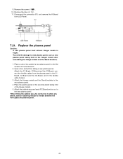
...215;1 ). 10. Disconnect the connector (K1) and remove the K-Board from the plasma panel to remain between the front glass and plasma panel. 24 Open a box and without Hanger metals is fragile. Place the plasma panel on , to the new plasma panel. *When fitting the cabinet assy, be careful not to allow ...any debris, dust or handling residue to the C1Board, C2-Board and the C3-Board, and fit the flexible cable holders. 3. Attach the C1-Board, C2-Board and the C3-Board, connect the ...
...215;1 ). 10. Disconnect the connector (K1) and remove the K-Board from the plasma panel to remain between the front glass and plasma panel. 24 Open a box and without Hanger metals is fragile. Place the plasma panel on , to the new plasma panel. *When fitting the cabinet assy, be careful not to allow ...any debris, dust or handling residue to the C1Board, C2-Board and the C3-Board, and fit the flexible cable holders. 3. Attach the C1-Board, C2-Board and the C3-Board, connect the ...
Service Manual
Page 26
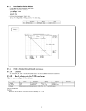
... electrolysis capacitors. 8.1.3.2. Set the picture controls as follows. P.C.B. Connect Oscilloscope to plasma video input. 2. 8.1.2. Initialization Pulse Adjust 1. Input the White signal to TPSC1 (SC). To remove P.C.B., wait 1 minute after P.C.B. Remarks 26 Picture menu : Vivid Normal : Set Aspect : Full 3. P.C.B. (Printed Circuit Board) exchange 8.1.3.1. Quick adjustment after power was off for NTSC, PAL, HD...
... electrolysis capacitors. 8.1.3.2. Set the picture controls as follows. P.C.B. Connect Oscilloscope to plasma video input. 2. 8.1.2. Initialization Pulse Adjust 1. Input the White signal to TPSC1 (SC). To remove P.C.B., wait 1 minute after P.C.B. Remarks 26 Picture menu : Vivid Normal : Set Aspect : Full 3. P.C.B. (Printed Circuit Board) exchange 8.1.3.1. Quick adjustment after power was off for NTSC, PAL, HD...

Service Manual
Page 46
P(P-2)-Board Schematic Diagram A ! P(P-2)-BOARD ETX2MM761MGN B HOT COLD COLD HOT TO P(P-1)-BOARD (P58) TO P(P-1)-BOARD (P52) C D TO P(P-1)-BOARD (P56) E TO P(P-1)-BOARD (P54) F 1 2 3 4 5 6 7 8 9 46 11.4.
P(P-2)-Board Schematic Diagram A ! P(P-2)-BOARD ETX2MM761MGN B HOT COLD COLD HOT TO P(P-1)-BOARD (P58) TO P(P-1)-BOARD (P52) C D TO P(P-1)-BOARD (P56) E TO P(P-1)-BOARD (P54) F 1 2 3 4 5 6 7 8 9 46 11.4.

Service Manual
Page 47
... R2542 47k R2520 220k R2525 820 D2520 LN1271RALTR POWER LED R2524 22k R2557 5.6k Q2511 2SD0601A0L SUB5V C.A.T.S.SENSOR STBY3.3V REMOCON R_LED_ON KEY3 K1 TO A-BOARD (A1) 1 SUB5V 2 C.A.T.S._SENSOR 3 STB3.3V 4 GND 5 RM_IN 6 R_LED_ON 7 GND 12 FL2500 J0MAB0000201 10 9 2 KEYSCAN3(OUT) GND 8 KEYSCAN3(IN) 1 S2 PUSH SW2500 K0F122A00172 POWER SW...
... R2542 47k R2520 220k R2525 820 D2520 LN1271RALTR POWER LED R2524 22k R2557 5.6k Q2511 2SD0601A0L SUB5V C.A.T.S.SENSOR STBY3.3V REMOCON R_LED_ON KEY3 K1 TO A-BOARD (A1) 1 SUB5V 2 C.A.T.S._SENSOR 3 STB3.3V 4 GND 5 RM_IN 6 R_LED_ON 7 GND 12 FL2500 J0MAB0000201 10 9 2 KEYSCAN3(OUT) GND 8 KEYSCAN3(IN) 1 S2 PUSH SW2500 K0F122A00172 POWER SW...

Service Manual
Page 50
A-Board (3/15) Schematic Diagram ! P S S AA_EA23 AA_EA16 AA_EA15 AA_EA14 AA_EA13 AA_EA12 AA_EA11 AA_EA10 AA_EA9 AA_EA20 AA_EA21 AA_XEWE0 ...R8580 Boundary Scan 10k R5137 10k R8529 33 TMS TRST TDI TDO TCK TO 1/15 19 20 21 22 23 24 25 26 27 50 A-BOARD TXN/A1EYUUS (3/15) DIGITAL,SD-CARD TP8568 C8506 16V 0.1u SUB3.3V 1 E0 2 E1 8 VCC 7 WC R8556 4.7k TP8569 ...TP8571 TO 1/15 SE_EEP_WP PORT9[4] EEPROM_WP SUB3.3V R8512 4.7k C8501 16V 0.1u IC8502 TVRQ500AHS NOR FLASH 56 N.C. 55 N.C. 54 A16 53 BYTE 52 Vss 51 DQ15/A-1 50 DQ7 49 DQ14 48 DQ6 47 DQ13 46 DQ5 45 DQ12 44 DQ4 43 ...
A-Board (3/15) Schematic Diagram ! P S S AA_EA23 AA_EA16 AA_EA15 AA_EA14 AA_EA13 AA_EA12 AA_EA11 AA_EA10 AA_EA9 AA_EA20 AA_EA21 AA_XEWE0 ...R8580 Boundary Scan 10k R5137 10k R8529 33 TMS TRST TDI TDO TCK TO 1/15 19 20 21 22 23 24 25 26 27 50 A-BOARD TXN/A1EYUUS (3/15) DIGITAL,SD-CARD TP8568 C8506 16V 0.1u SUB3.3V 1 E0 2 E1 8 VCC 7 WC R8556 4.7k TP8569 ...TP8571 TO 1/15 SE_EEP_WP PORT9[4] EEPROM_WP SUB3.3V R8512 4.7k C8501 16V 0.1u IC8502 TVRQ500AHS NOR FLASH 56 N.C. 55 N.C. 54 A16 53 BYTE 52 Vss 51 DQ15/A-1 50 DQ7 49 DQ14 48 DQ6 47 DQ13 46 DQ5 45 DQ12 44 DQ4 43 ...

Service Manual
Page 51
A-BOARD TXN/A1EYUUS (4/15) POWER SUPPLY VJ5600 P F15V D5692 MAZ80560LL R5644 2.2k R5638 10k R5635 22k Q5603 B1ABCF000231 R5646 10k R5636 68k C5644 16V 0.01u C5688 ... CD 2 VDD 3 OUT C5663 1 VSS 4 10V 10u IC5606 C0EBF0000354 C5667 50V 100p STB RESET 28 29 30 31 32 33 34 35 36 51 11.9. A-Board (4/15) Schematic Diagram !
A-BOARD TXN/A1EYUUS (4/15) POWER SUPPLY VJ5600 P F15V D5692 MAZ80560LL R5644 2.2k R5638 10k R5635 22k Q5603 B1ABCF000231 R5646 10k R5636 68k C5644 16V 0.01u C5688 ... CD 2 VDD 3 OUT C5663 1 VSS 4 10V 10u IC5606 C0EBF0000354 C5667 50V 100p STB RESET 28 29 30 31 32 33 34 35 36 51 11.9. A-Board (4/15) Schematic Diagram !

Service Manual
Page 52
.../A1EYUUS (5/15) CONNECTOR 1 V1_S_DET 2 SOUND15V TP3520 TP3518 TP3519 R3571 0 R3570 0 TO P-BOARD (P6,P7) A6 TP3521 1 +15V_S 2 +15V_S 3 +15V_S 4 S_GND IIC2 TO 7,10/15 SYS_SCL0 SYS_SDA0 SYS_SCL0 SYS_SDA0 SUB9V 5 S_GND F15V TP3522 TP3502 ... AG_TV_SUB_ON TO 7,10/15 STB5V TP3526 TP3500 TP3501 TP3527 TP3528 TP3523 6 S_GND 7 F+15V 8 F+15V 9 F+15V 10 GND 11 GND 12 GND 13 14 15 TO K-BOARD (K1) TP4004 RM R_LED KEY3 A1 1 2 3 4 5 6 7 8 TP4006 TP4003 TP4001 TP4002 TP4005 SUB5V JS4038 STB3.3V JS4010 C4075 16V 0.1u FL4000 J0HAAB000036 1 3 2 4 FL4008 J0HAAB000036 1 3 ...
.../A1EYUUS (5/15) CONNECTOR 1 V1_S_DET 2 SOUND15V TP3520 TP3518 TP3519 R3571 0 R3570 0 TO P-BOARD (P6,P7) A6 TP3521 1 +15V_S 2 +15V_S 3 +15V_S 4 S_GND IIC2 TO 7,10/15 SYS_SCL0 SYS_SDA0 SYS_SCL0 SYS_SDA0 SUB9V 5 S_GND F15V TP3522 TP3502 ... AG_TV_SUB_ON TO 7,10/15 STB5V TP3526 TP3500 TP3501 TP3527 TP3528 TP3523 6 S_GND 7 F+15V 8 F+15V 9 F+15V 10 GND 11 GND 12 GND 13 14 15 TO K-BOARD (K1) TP4004 RM R_LED KEY3 A1 1 2 3 4 5 6 7 8 TP4006 TP4003 TP4001 TP4002 TP4005 SUB5V JS4038 STB3.3V JS4010 C4075 16V 0.1u FL4000 J0HAAB000036 1 3 2 4 FL4008 J0HAAB000036 1 3 ...

Service Manual
Page 53
... R2119 3.3 C2147 50V 1000p C2149 50V 1000p TP2100 TP2101 TP2102 TP2103 C2146 50V 1000p A12 TO SPEAKER_L 1 L+ 2 L- A11 TO SPEAKER_R 1 R+ 2 NC 3 R- 11.11. A-BOARD TXN/A1EYUUS (6/15) 2 AV SW,SPEAKER OUT OPERATE MUTE OPERATE RESET TP2104 3 C2153 16V 0.1u 4 V1_C V1_Y V1_V PC_R_IN PC_H_IN PC_G_IN PC_V_IN PC_B_IN R3058 C3001...V2_R JS3051 V2_L JS3052 V2_V JS3054 R3716 39k R3717 39k R-G R JK3701 L-G K4AK08B00004 L V-G SIDE TERMINAL V SHIELD V L R SHIELD 46 47 48 49 50 51 52 53 54 53 A-Board (6/15) Schematic Diagram AMP_MUTE AG_AUDIO_XRST AG_SOUND_SOS 1 !
... R2119 3.3 C2147 50V 1000p C2149 50V 1000p TP2100 TP2101 TP2102 TP2103 C2146 50V 1000p A12 TO SPEAKER_L 1 L+ 2 L- A11 TO SPEAKER_R 1 R+ 2 NC 3 R- 11.11. A-BOARD TXN/A1EYUUS (6/15) 2 AV SW,SPEAKER OUT OPERATE MUTE OPERATE RESET TP2104 3 C2153 16V 0.1u 4 V1_C V1_Y V1_V PC_R_IN PC_H_IN PC_G_IN PC_V_IN PC_B_IN R3058 C3001...V2_R JS3051 V2_L JS3052 V2_V JS3054 R3716 39k R3717 39k R-G R JK3701 L-G K4AK08B00004 L V-G SIDE TERMINAL V SHIELD V L R SHIELD 46 47 48 49 50 51 52 53 54 53 A-Board (6/15) Schematic Diagram AMP_MUTE AG_AUDIO_XRST AG_SOUND_SOS 1 !

Service Manual
Page 54
A-Board (7/15) Schematic Diagram ! A-BOARD TXN/A1EYUUS (7/15) SYSTEM MPU,EEPROM SUB5V R1212 47k R1211 68k SUB9V R1213 68k R1214 33k HDMI TO 8/15 AG_EDID_WP AG_HDMI_CEC LVDS Out TO 5,10/... 0.01u 1k R1224 47k C1108 16V 0.1u BOOT SYSMPU_EEP_WP SDA1 SCL1 CEC_OUT2 KEY1 AI RF_AF1 FACT 49 50 51 52 P32/HWR 53 P40/CS0 54 P41/CS1 55 P42/CS2 56 P60/SCK 57 P61/SO/SDA 58 P62/SI/SCL 59 P63/INT0 60 P50/AN0 61 P51/AN1... 8 Vcc 7 WP 6 SCL 5 SDA R1209 4.7k TP1102 TP1100 TP1101 IC1101 TVRQ731S EEPROM TP1105 R1201 4.7k R1200 4.7k 55 56 57 58 59 60 61 62 54 63 11.12.
A-Board (7/15) Schematic Diagram ! A-BOARD TXN/A1EYUUS (7/15) SYSTEM MPU,EEPROM SUB5V R1212 47k R1211 68k SUB9V R1213 68k R1214 33k HDMI TO 8/15 AG_EDID_WP AG_HDMI_CEC LVDS Out TO 5,10/... 0.01u 1k R1224 47k C1108 16V 0.1u BOOT SYSMPU_EEP_WP SDA1 SCL1 CEC_OUT2 KEY1 AI RF_AF1 FACT 49 50 51 52 P32/HWR 53 P40/CS0 54 P41/CS1 55 P42/CS2 56 P60/SCK 57 P61/SO/SDA 58 P62/SI/SCL 59 P63/INT0 60 P50/AN0 61 P51/AN1... 8 Vcc 7 WP 6 SCL 5 SDA R1209 4.7k TP1102 TP1100 TP1101 IC1101 TVRQ731S EEPROM TP1105 R1201 4.7k R1200 4.7k 55 56 57 58 59 60 61 62 54 63 11.12.

Service Manual
Page 56
... VINP_VSB VINN_VSB TP8300 TP8301 TP8302 TO 7/15 AG_RF_AFT1 RF_L RF_R RF_V TO 5/15 73 74 75 76 77 78 79 80 81 56 11.14. A-Board (9/15) Schematic Diagram ! A-BOARD TXN/A1EYUUS (9/15) TUNER ANALOG VIDEO_OUT RF_V ANALOG !
... VINP_VSB VINN_VSB TP8300 TP8301 TP8302 TO 7/15 AG_RF_AFT1 RF_L RF_R RF_V TO 5/15 73 74 75 76 77 78 79 80 81 56 11.14. A-Board (9/15) Schematic Diagram ! A-BOARD TXN/A1EYUUS (9/15) TUNER ANALOG VIDEO_OUT RF_V ANALOG !

Service Manual
Page 57
11.15. A-BOARD TXN/A1EYUUS (10/15) CONNECTOR SYSTEM MPU TO 1,7/15 AG_SRQ_SYSMPU R4233 22 TP8503 STB5V TP8572 SCL1_EEP SDA1_EEP SYS_SCL1_EEP SYS_SDA1_EEP AR_PANEL_SCL AR_PANEL_SDA D_IIC_CONT D_PCB_MODE TO 11/... C4775 16V 0.1u C4776 C4777 50V 16V 1000p 0.1u C4778 16V 0.1u C4779 16V 0.1u 82 83 84 85 86 87 88 89 90 57 A-Board (10/15) Schematic Diagram !
11.15. A-BOARD TXN/A1EYUUS (10/15) CONNECTOR SYSTEM MPU TO 1,7/15 AG_SRQ_SYSMPU R4233 22 TP8503 STB5V TP8572 SCL1_EEP SDA1_EEP SYS_SCL1_EEP SYS_SDA1_EEP AR_PANEL_SCL AR_PANEL_SDA D_IIC_CONT D_PCB_MODE TO 11/... C4775 16V 0.1u C4776 C4777 50V 16V 1000p 0.1u C4778 16V 0.1u C4779 16V 0.1u 82 83 84 85 86 87 88 89 90 57 A-Board (10/15) Schematic Diagram !


