54" Plasma Tv
Page 5
... to climb on a sloped or unstable surface. Leave a space of the TV by Panasonic Corporation. • Wall-hanging bracket (Angled) TY-WK4P1RW (TC-42PS14, TC-50PS14) TY-WK5P1RW (TC-54PS14) Be sure to ask a qualified technician to its stand on the Plasma TV Place or install the Plasma TV where it , a short-circuit may occur which could cause a fire. Moving...
... to climb on a sloped or unstable surface. Leave a space of the TV by Panasonic Corporation. • Wall-hanging bracket (Angled) TY-WK4P1RW (TC-42PS14, TC-50PS14) TY-WK5P1RW (TC-54PS14) Be sure to ask a qualified technician to its stand on the Plasma TV Place or install the Plasma TV where it , a short-circuit may occur which could cause a fire. Moving...
54" Plasma Tv
Page 6
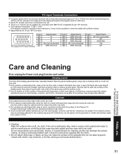
...• Care should be pulled or grabbed by the display and wall mount manufacturers. • If you have any dust from your Plasma TV. Panasonic recommends that are required for installation. Display panel is made of which might damage the insulation and cause a fire. Care should be taken... reflected light from the power supply cord and plug regularly. Do not apply strong force or impact to the manufacturer's recommendations. This Plasma TV radiates infrared rays; therefore, it cannot be used as steps, such as a chest of your retailer about your ability to avoid ...
...• Care should be pulled or grabbed by the display and wall mount manufacturers. • If you have any dust from your Plasma TV. Panasonic recommends that are required for installation. Display panel is made of which might damage the insulation and cause a fire. Care should be taken... reflected light from the power supply cord and plug regularly. Do not apply strong force or impact to the manufacturer's recommendations. This Plasma TV radiates infrared rays; therefore, it cannot be used as steps, such as a chest of your retailer about your ability to avoid ...

54" Plasma Tv
Page 7
...; SD Card photo Video game •■ • Set up • Computer image Do not place the unit where it's exposed to remain on the plasma screen ("Image retention").
...; SD Card photo Video game •■ • Set up • Computer image Do not place the unit where it's exposed to remain on the plasma screen ("Image retention").
54" Plasma Tv
Page 8
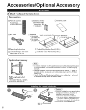
...TBLX0089 (TC-50PS14) TBLX0102 (TC-54PS14) Operating Instructions Viera Concierge and basic instruction for HDTV Product Registration Card (U.S.A.) Customer Care Plan Card (U.S.A.) Optional Accessory Wall-hanging bracket (angle) TY-WK4P1RW (for 42"/50") TY-WK5P1RW (for 54") Note In order to maintain the TV's ...hanging brackets. Carefully read the instructions accompanying the plasma TV stand or pedestal, and be absolutely sure to ask your dealer or a licensed contractor to prevent the TV from tipping over. Handle the TV carefully during installation since subjecting it to impact ...
...TBLX0089 (TC-50PS14) TBLX0102 (TC-54PS14) Operating Instructions Viera Concierge and basic instruction for HDTV Product Registration Card (U.S.A.) Customer Care Plan Card (U.S.A.) Optional Accessory Wall-hanging bracket (angle) TY-WK4P1RW (for 42"/50") TY-WK5P1RW (for 54") Note In order to maintain the TV's ...hanging brackets. Carefully read the instructions accompanying the plasma TV stand or pedestal, and be absolutely sure to ask your dealer or a licensed contractor to prevent the TV from tipping over. Handle the TV carefully during installation since subjecting it to impact ...
54" Plasma Tv
Page 15
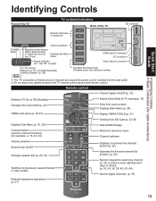
... operations (p. 37) 15 Quick Start Guide Identifying Controls Basic Connection (AV cable connections) Identifying Controls Front of the TV TV controls/indicators Back of the TV Selects channels in sequence SD card slot Volume up/down POWER button Remote control sensor Within about 23 feet (7 meters... Volume up/down Sound mute On/Off Changes aspect ratio (p. 20, 47) Switches to previously viewed channel or input modes. sensor Plasma C.A.T.S. (Contrast Automatic Tracking System). (p. 28) Note Changes the input mode Chooses menu and submenu entries. Displays or removes the channel...
... operations (p. 37) 15 Quick Start Guide Identifying Controls Basic Connection (AV cable connections) Identifying Controls Front of the TV TV controls/indicators Back of the TV Selects channels in sequence SD card slot Volume up/down POWER button Remote control sensor Within about 23 feet (7 meters... Volume up/down Sound mute On/Off Changes aspect ratio (p. 20, 47) Switches to previously viewed channel or input modes. sensor Plasma C.A.T.S. (Contrast Automatic Tracking System). (p. 28) Note Changes the input mode Chooses menu and submenu entries. Displays or removes the channel...
54" Plasma Tv
Page 51
... so will not be displayed properly if the signals exceed 1,200 lines.) Some PC models cannot be input are those with the surface of the Plasma TV. Avoid contact with a soft, dry cloth. Do not use an adapter for computers with IBM PC/AT compatible D-sub 15P terminal. PC Input Terminals Connection...
... so will not be displayed properly if the signals exceed 1,200 lines.) Some PC models cannot be input are those with the surface of the Plasma TV. Avoid contact with a soft, dry cloth. Do not use an adapter for computers with IBM PC/AT compatible D-sub 15P terminal. PC Input Terminals Connection...
54" Plasma Tv
Page 53
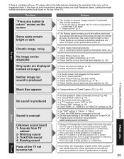
... This is unusual Unknown sound heard 1- Check the HDMI device connected to "Linear PCM". The TV may have no impact on , an electrical component in SD mode. • "Image retention" (p. 7) The Plasma panel is made up of images Neither image nor sound is produced Check Picture menu (p. 28) ... to "Stereo" or "Mono". This is not a sign of the TV). Buzzing sound Parts of the TV set is on the rear of faulty operation or a malfunction. 3- Sometimes a few million pixels and is produced with your local Panasonic dealer, quoting the model number and serial number (both found on . ...
... This is unusual Unknown sound heard 1- Check the HDMI device connected to "Linear PCM". The TV may have no impact on , an electrical component in SD mode. • "Image retention" (p. 7) The Plasma panel is made up of images Neither image nor sound is produced Check Picture menu (p. 28) ... to "Stereo" or "Mono". This is not a sign of the TV). Buzzing sound Parts of the TV set is on the rear of faulty operation or a malfunction. 3- Sometimes a few million pixels and is produced with your local Panasonic dealer, quoting the model number and serial number (both found on . ...
54" Plasma Tv
Page 54
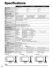
...(41.6 inches measured diagonally) 50 " class (49.9 inches measured diagonally) 54" class (54.1 inches measured diagonally 36.2 " × 20.4 " × 41.6 " 43.5 " × 24.4 " × 49.9 " 47.1 " × 26.5 " × 54.1 " (921 mm × 518 mm × 1,057 mm) (1,105...; 2 0.5 V [rms] TYPE A Connector × 3 • This TV supports "HDAVI Control 4" function. Specifications Power Source Maximum TC-42PS14 AC 120 V, 60 Hz 485 W TC-50PS14 584 W TC-54PS14 599 W Power Consumption panel Plasma Display Standby condition Drive method Aspect Ratio Visible screen size (W × H &#...
...(41.6 inches measured diagonally) 50 " class (49.9 inches measured diagonally) 54" class (54.1 inches measured diagonally 36.2 " × 20.4 " × 41.6 " 43.5 " × 24.4 " × 49.9 " 47.1 " × 26.5 " × 54.1 " (921 mm × 518 mm × 1,057 mm) (1,105...; 2 0.5 V [rms] TYPE A Connector × 3 • This TV supports "HDAVI Control 4" function. Specifications Power Source Maximum TC-42PS14 AC 120 V, 60 Hz 485 W TC-50PS14 584 W TC-54PS14 599 W Power Consumption panel Plasma Display Standby condition Drive method Aspect Ratio Visible screen size (W × H &#...
54" Plasma Tv
Page 55
... carry-in the United States or Puerto Rico. and Puerto Rico only) PANASONIC CONSUMER ELECTRONICS COMPANY, DIVISION OF PANASONIC CORPORATION OF NORTH AMERICA One Panasonic Way Secaucus, New Jersey 07094 Panasonic Plasma Television Limited Warranty Limited Warranty Coverage If your product does not work properly ...remove or re-install an installed unit if applicable, or travel to and from state to your dealer or Service Center. PLASMA TV CATEGORIES Up to the warrantor's Consumer Affairs Department at its option either (a) repair your product with new or refurbished parts,...
... carry-in the United States or Puerto Rico. and Puerto Rico only) PANASONIC CONSUMER ELECTRONICS COMPANY, DIVISION OF PANASONIC CORPORATION OF NORTH AMERICA One Panasonic Way Secaucus, New Jersey 07094 Panasonic Plasma Television Limited Warranty Limited Warranty Coverage If your product does not work properly ...remove or re-install an installed unit if applicable, or travel to and from state to your dealer or Service Center. PLASMA TV CATEGORIES Up to the warrantor's Consumer Affairs Department at its option either (a) repair your product with new or refurbished parts,...
Service Manual
Page 2
...(PbF 5 3 Service Navigation 6 3.1. Wiring (1 37 10.3. A-Board (4/15) Schematic Diagram 51 11.10. A-Board (7/15) Schematic Diagram 54 11.13. A-Board (9/15) Schematic Diagram 56 11.15. C3-Board (1/2) Schematic Diagram 67 11.26. How to Electrostatically Sensitive (ES) ...Devices ----------4 2.2. No Picture 16 6.5. Remove the SS2-Board 21 7.13. Replace the plasma panel 24 8 Measurements and Adjustments 25 8.1. Block (4/4) Diagram 35 10 Wiring Connection Diagram 37 10.1. A-Board (5/15) Schematic Diagram 52...
...(PbF 5 3 Service Navigation 6 3.1. Wiring (1 37 10.3. A-Board (4/15) Schematic Diagram 51 11.10. A-Board (7/15) Schematic Diagram 54 11.13. A-Board (9/15) Schematic Diagram 56 11.15. C3-Board (1/2) Schematic Diagram 67 11.26. How to Electrostatically Sensitive (ES) ...Devices ----------4 2.2. No Picture 16 6.5. Remove the SS2-Board 21 7.13. Replace the plasma panel 24 8 Measurements and Adjustments 25 8.1. Block (4/4) Diagram 35 10 Wiring Connection Diagram 37 10.1. A-Board (5/15) Schematic Diagram 52...

Service Manual
Page 6
... P Power Supply Function A DC-DC Converter, Tuner Speaker out, AV Terminal, AV Switch, PC Digital Signal Processor, SYSTEM MPU, HDMI Switch Seine 3LV Format Converter, Plasma AI, Sub-Field Processor K Remote receiver, Power LED, C.A.T.S sensor S Power Switch GK Key Switch Board Name C1 C2 C3 SC SS SS2 SU SD Function...
... P Power Supply Function A DC-DC Converter, Tuner Speaker out, AV Terminal, AV Switch, PC Digital Signal Processor, SYSTEM MPU, HDMI Switch Seine 3LV Format Converter, Plasma AI, Sub-Field Processor K Remote receiver, Power LED, C.A.T.S sensor S Power Switch GK Key Switch Board Name C1 C2 C3 SC SS SS2 SU SD Function...
Service Manual
Page 8
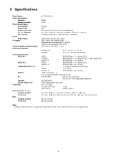
....0 kg) 83.8 lb. (38.0 kg) Note • Design and Specifications are approximate. 8 4 Specifications Power Source Power Consumption Maximum Standby condition Plasma Display panel Drive method Aspect Ratio Visible screen size (W × H × Diagonal) (No. of pixels) Sound Audio Output PC signals Channel ...OUT FEATURES Dimensions (W × H × D) Including pedestal TV Set only Mass Including pedestal TV Set only AC 120 V, 60 Hz 599 W 0.3 W AC type 16:9 54 inch class (54.1 inches measured diagonally) 47.1 inch × 26.5 inch × 54.1 inch (1,198 mm × 673 mm × 1,374 ...
....0 kg) 83.8 lb. (38.0 kg) Note • Design and Specifications are approximate. 8 4 Specifications Power Source Power Consumption Maximum Standby condition Plasma Display panel Drive method Aspect Ratio Visible screen size (W × H × Diagonal) (No. of pixels) Sound Audio Output PC signals Channel ...OUT FEATURES Dimensions (W × H × D) Including pedestal TV Set only Mass Including pedestal TV Set only AC 120 V, 60 Hz 599 W 0.3 W AC type 16:9 54 inch class (54.1 inches measured diagonally) 47.1 inch × 26.5 inch × 54.1 inch (1,198 mm × 673 mm × 1,374 ...
Service Manual
Page 17
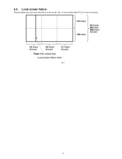
for each local area. Fig-1 is the possible defect P.C.B. Fig-1 17 Local screen failure Plasma display may have local area failure on the screen. 6.5.
for each local area. Fig-1 is the possible defect P.C.B. Fig-1 17 Local screen failure Plasma display may have local area failure on the screen. 6.5.

Service Manual
Page 21
... section from the servicing stand and lay on a flat surface such as a table (covered by a soft cloth) with the Plasma panel surface facing downward. 2. Disconnect the bridge connector (SS21-SS24). 6. connect the flexible cable (SS58). 3. Remove the Hanger metals (L, R) fastening screws (×4 each ) and the ...
... section from the servicing stand and lay on a flat surface such as a table (covered by a soft cloth) with the Plasma panel surface facing downward. 2. Disconnect the bridge connector (SS21-SS24). 6. connect the flexible cable (SS58). 3. Remove the Hanger metals (L, R) fastening screws (×4 each ) and the ...
Service Manual
Page 22
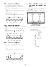
...2. Disconnect the connector (C14). 7. Remove the flexible cables holder fastening screws (×10 ). 4. Disconnect the flexible cable (C36). 6. For leaving the plasma panel from the Cabinet assy (glass) 1. 7.15. Remove the C1-Board 1. Remove the flexible cables holder fastening screws (×10 ). 4. Remove the... unit. (See section 7.4.) 2. Remove the C2-Board 1. Remove the screws (×4 ) and remove the C1-Board. 7.18. Remove the Plasma panel section from the front frame, pull the bottom of the cabinet assy forward, lift, and remove. 7.17. Remove the screws (×4 )...
...2. Disconnect the connector (C14). 7. Remove the flexible cables holder fastening screws (×10 ). 4. Disconnect the flexible cable (C36). 6. For leaving the plasma panel from the Cabinet assy (glass) 1. 7.15. Remove the C1-Board 1. Remove the flexible cables holder fastening screws (×10 ). 4. Remove the... unit. (See section 7.4.) 2. Remove the C2-Board 1. Remove the screws (×4 ) and remove the C1-Board. 7.18. Remove the Plasma panel section from the front frame, pull the bottom of the cabinet assy forward, lift, and remove. 7.17. Remove the screws (×4 )...
Service Manual
Page 24
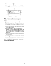
...Board and so on the flat surface of the Hanger metals after assembling the Hanger metals and the Stand brackets. 1. 9. Place a carton box packed a new plasma panel on , to the new plasma panel. *When fitting the cabinet assy, be careful not to allow any debris, dust or handling residue to new... plasma panel, carry a new plasma panel taking a new plasma panel; Attach the Hanger metals and the Stand brackets to the C1Board, C2-Board and the C3-Board, and fit the flexible cable holders. 3. ...
...Board and so on the flat surface of the Hanger metals after assembling the Hanger metals and the Stand brackets. 1. 9. Place a carton box packed a new plasma panel on , to the new plasma panel. *When fitting the cabinet assy, be careful not to allow any debris, dust or handling residue to new... plasma panel, carry a new plasma panel taking a new plasma panel; Attach the Hanger metals and the Stand brackets to the C1Board, C2-Board and the C3-Board, and fit the flexible cable holders. 3. ...

Service Manual
Page 25
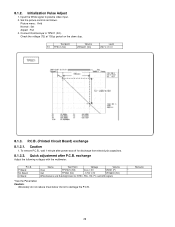
... as follows. Picture menu: Vivid Normal: Set Aspect: Full Caution 1. Vsus Ve Vset Vad Vscn Name Vda *See the Panel label. Input a white signal to plasma video input. 2. Adjustments Adjust driver section voltages referring the panel data on the panel data label. Item / Preparation 1. Test Point TPVSUS (SS) TPVE (SS) TPVSET...
... as follows. Picture menu: Vivid Normal: Set Aspect: Full Caution 1. Vsus Ve Vset Vad Vscn Name Vda *See the Panel label. Input a white signal to plasma video input. 2. Adjustments Adjust driver section voltages referring the panel data on the panel data label. Item / Preparation 1. Test Point TPVSUS (SS) TPVE (SS) TPVSET...
Service Manual
Page 26
...) exchange 8.1.3.1. To remove P.C.B., wait 1 minute after P.C.B. Remarks 26 Picture menu : Vivid Normal : Set Aspect : Full 3. Input the White signal to TPSC1 (SC). Connect Oscilloscope to plasma video input. 2. Check the voltage (T2) at 100μs period on the down slop. Caution: Absolutely do not reduce Vsus below Ve not to damage...
...) exchange 8.1.3.1. To remove P.C.B., wait 1 minute after P.C.B. Remarks 26 Picture menu : Vivid Normal : Set Aspect : Full 3. Input the White signal to TPSC1 (SC). Connect Oscilloscope to plasma video input. 2. Check the voltage (T2) at 100μs period on the down slop. Caution: Absolutely do not reduce Vsus below Ve not to damage...
Service Manual
Page 35
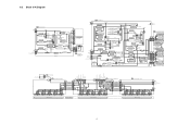
... Q16818 TPVAD CEL DRIVE CIRCUIT CML Q16422 Q16423 Q16424 GEN. DRIVER Q16101 UEH Q16102 TPSS1 D16280 Q16280 ERROR DET D16282 SS 53 1 2 13 SS 55 1 PLASMA PANEL 2 PANEL SUSTAIN 13 ELECTRODE SS 56 1 2 13 SS 58 1 2 13 SS SS 21 24 7 7 1 1 6 6 SS2 SUSTAIN CONNECTOR (LOWER) SC SCAN DRIVE P2... SCNR_PRO Vscn SIU OC1 OC2 CLK SEL SU SCAN OUT (UPPER) IC14601-04 SCAN DRIVER SU 41 8 SCAN 4 DRIVER 2 IC14605-08 SU1B-SU5B SU 11 PLASMA PANEL PANEL SCAN ELECTRODES SD 11 SD1B-SD5B IC14801-04 SD 42 3 8 9 5 6 4 2 SD 46 5V 1 SCAN DRIVER SCAN DRIVER IC14805-08 VHIZ VSET23...
... Q16818 TPVAD CEL DRIVE CIRCUIT CML Q16422 Q16423 Q16424 GEN. DRIVER Q16101 UEH Q16102 TPSS1 D16280 Q16280 ERROR DET D16282 SS 53 1 2 13 SS 55 1 PLASMA PANEL 2 PANEL SUSTAIN 13 ELECTRODE SS 56 1 2 13 SS 58 1 2 13 SS SS 21 24 7 7 1 1 6 6 SS2 SUSTAIN CONNECTOR (LOWER) SC SCAN DRIVE P2... SCNR_PRO Vscn SIU OC1 OC2 CLK SEL SU SCAN OUT (UPPER) IC14601-04 SCAN DRIVER SU 41 8 SCAN 4 DRIVER 2 IC14605-08 SU1B-SU5B SU 11 PLASMA PANEL PANEL SCAN ELECTRODES SD 11 SD1B-SD5B IC14801-04 SD 42 3 8 9 5 6 4 2 SD 46 5V 1 SCAN DRIVER SCAN DRIVER IC14805-08 VHIZ VSET23...

Service Manual
Page 94
... TMME332 TMME332 TMME345 TMW2AA011 TMW2AF0151 TMXX055 TMXX062 TMZ2AX0391 TPD169487 TPEB362 TQB2AA0814 TSXL519 TSXL661 Part Name & Description BATTERY COVER AC CORD PLASMA DISPLAY PANEL REMOTE CONTROLLER STAND POLE R STAND POLE L PEDESTAL STAND PANASONIC BADGE POWER BUTTON SCREW(AC INRET:2) SCREW SCREW (BC TOP:4) SCREW(A-PRINT:4) SCREW SCREW FRONT GLASS LED PANEL ADJUSTMENT COVER...
... TMME332 TMME332 TMME345 TMW2AA011 TMW2AF0151 TMXX055 TMXX062 TMZ2AX0391 TPD169487 TPEB362 TQB2AA0814 TSXL519 TSXL661 Part Name & Description BATTERY COVER AC CORD PLASMA DISPLAY PANEL REMOTE CONTROLLER STAND POLE R STAND POLE L PEDESTAL STAND PANASONIC BADGE POWER BUTTON SCREW(AC INRET:2) SCREW SCREW (BC TOP:4) SCREW(A-PRINT:4) SCREW SCREW FRONT GLASS LED PANEL ADJUSTMENT COVER...


