Operating Instructions
Page 5
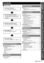
... installing 9 Cautions on use 9 Others 10 Security 10 Accessories 11 Preparation Technical Information 34 List of the projector 23 Resetting to the factory default 23 Menu Navigation 24 Main menu and Sub-menu 24 Navigating through the menu 27 Maintenance 4. Adjust the image See "Menu Navigation" on page 19. Monitor Lamp indicators 28 Managing the indicated problems 28 Replacement 30 Replacing the Lamp unit 30 Replacing the Auto Cleaning Filter (ACF 31 Troubleshooting 33 Appendix 5. Start projecting...
... installing 9 Cautions on use 9 Others 10 Security 10 Accessories 11 Preparation Technical Information 34 List of the projector 23 Resetting to the factory default 23 Menu Navigation 24 Main menu and Sub-menu 24 Navigating through the menu 27 Maintenance 4. Adjust the image See "Menu Navigation" on page 19. Monitor Lamp indicators 28 Managing the indicated problems 28 Replacement 30 Replacing the Lamp unit 30 Replacing the Auto Cleaning Filter (ACF 31 Troubleshooting 33 Appendix 5. Start projecting...
Operating Instructions
Page 9
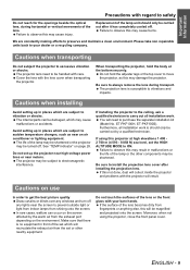
... the openings beside the optical lens, during transport. See "TEMP indicator" on use In order to get the best picture quality Draw curtains or blinds over any windows and turn off any lights near the screen to prevent outside light or light from indoor lamps from the set which may cause malfunctions or accidents. If using the projector, close the front panel cover. Failure to preserve and maintain a clean environment...
... the openings beside the optical lens, during transport. See "TEMP indicator" on use In order to get the best picture quality Draw curtains or blinds over any windows and turn off any lights near the screen to prevent outside light or light from indoor lamps from the set which may cause malfunctions or accidents. If using the projector, close the front panel cover. Failure to preserve and maintain a clean environment...
Operating Instructions
Page 10
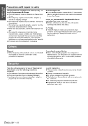
... or chipping damage. The brightness of the lamp depends on the duration of your password regularly. The Authorized Service Center will never ask you use the power cord supplied with the adjustable feet or projection lens cover removed. Password the projector and restrict access to confirm the correct procedure for the password. Especially the consecutive use projectors with the corresponding device and a commercially available shielded interface cable. The lamp may...
... or chipping damage. The brightness of the lamp depends on the duration of your password regularly. The Authorized Service Center will never ask you use the power cord supplied with the adjustable feet or projection lens cover removed. Password the projector and restrict access to confirm the correct procedure for the password. Especially the consecutive use projectors with the corresponding device and a commercially available shielded interface cable. The lamp may...
Operating Instructions
Page 12
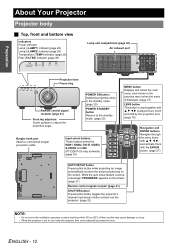
...Preparation About Your Projector Projector body J Top, front and bottom view Indicators Power indicator Lamp1 (LAMP1) indicator (page 28) Lamp2 (LAMP2) indicator (page 28) Temperature (TEMP) indicator (page 28) Filter (FILTER) indicator (page 29) STANDBY(RED)/ ON(GREEN) LAMP TEMP FILTER Lamp unit compartment (page 30) Air exhaust port STANDBY(RED)/ ON(GREEN) LAMP TEMP FILTER Projection lens Focus ring Remote control signal receptor (page 21) Front leg adjusters Screw up/down to black out the projector. (page 22) NOTE: • Do not cover the ventilation openings or place...
...Preparation About Your Projector Projector body J Top, front and bottom view Indicators Power indicator Lamp1 (LAMP1) indicator (page 28) Lamp2 (LAMP2) indicator (page 28) Temperature (TEMP) indicator (page 28) Filter (FILTER) indicator (page 29) STANDBY(RED)/ ON(GREEN) LAMP TEMP FILTER Lamp unit compartment (page 30) Air exhaust port STANDBY(RED)/ ON(GREEN) LAMP TEMP FILTER Projection lens Focus ring Remote control signal receptor (page 21) Front leg adjusters Screw up/down to black out the projector. (page 22) NOTE: • Do not cover the ventilation openings or place...

Operating Instructions
Page 13
.... Auto Cleaning Filter (ACF) compartment (page 31) NOTE: • Switch on /off. (page 20) AC IN terminal Connect the power cord to supply electronic power to the projector. (page 20) Security lock Attach the commercial shackle lock, manufactured by Kensington, to a computer. Air intake port Air intake port POWER button Switch the projector on the POWER button of the projector body that is located near the terminals before using the control buttons. • Do not cover the ventilation openings...
.... Auto Cleaning Filter (ACF) compartment (page 31) NOTE: • Switch on /off. (page 20) AC IN terminal Connect the power cord to supply electronic power to the projector. (page 20) Security lock Attach the commercial shackle lock, manufactured by Kensington, to a computer. Air intake port Air intake port POWER button Switch the projector on the POWER button of the projector body that is located near the terminals before using the control buttons. • Do not cover the ventilation openings...
Operating Instructions
Page 14
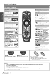
... battery life. • See "Remote control operation" on screen indications. (page 22) TEST PATTERN button Displays the test pattern. (page 22) Numeric (0 - 9) buttons Enter ID number of the remote control, adjustment values of the projector body that is displayed. (page 27) ON SCREEN button Displays and clears the on page 21. Preparation About Your Projector Remote control POWER ON and POWER STANDBY buttons POWER ON: Starts the projection while in the standby mode. POWER STANDBY: Returns to the standby mode. (page 19) INPUT SELECT buttons These buttons...
... battery life. • See "Remote control operation" on screen indications. (page 22) TEST PATTERN button Displays the test pattern. (page 22) Numeric (0 - 9) buttons Enter ID number of the remote control, adjustment values of the projector body that is displayed. (page 27) ON SCREEN button Displays and clears the on page 21. Preparation About Your Projector Remote control POWER ON and POWER STANDBY buttons POWER ON: Starts the projection while in the standby mode. POWER STANDBY: Returns to the standby mode. (page 19) INPUT SELECT buttons These buttons...
Operating Instructions
Page 16
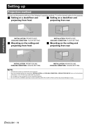
... CONDITION in PROJECTOR SETUP menu on the functional instructions in the projector, J Setting on a desk/floor and J Setting on a desk/floor and projecting from front projecting from rear INSTALLATION: FRONT/FLOOR COOLING CONDITION: FLOOR SETTING J Mounting on the ceiling and projecting from front INSTALLATION: REAR/FLOOR COOLING CONDITION: FLOOR SETTING J Mounting on the ceiling and projecting from rear INSTALLATION: FRONT/CEILING COOLING CONDITION: CEILING SETTING INSTALLATION: REAR/CEILING COOLING CONDITION: CEILING SETTING NOTE: • A translucent screen is required...
... CONDITION in PROJECTOR SETUP menu on the functional instructions in the projector, J Setting on a desk/floor and J Setting on a desk/floor and projecting from front projecting from rear INSTALLATION: FRONT/FLOOR COOLING CONDITION: FLOOR SETTING J Mounting on the ceiling and projecting from front INSTALLATION: REAR/FLOOR COOLING CONDITION: FLOOR SETTING J Mounting on the ceiling and projecting from rear INSTALLATION: FRONT/CEILING COOLING CONDITION: CEILING SETTING INSTALLATION: REAR/CEILING COOLING CONDITION: CEILING SETTING NOTE: • A translucent screen is required...
Operating Instructions
Page 17
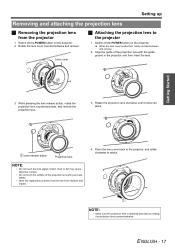
... not touch the lens signal contact. Rotate the lens cover counterclockwise and remove. Switch off the POWER button on the projector. Rotate the projection lens clockwise until it will be free from the projector 1. ENGLISH - 17 Switch off the POWER button on the projector. 2. Getting Started 3. Dust or dirt may cause defective contact. • Do not touch the surface of the projection lens with your bare hands. • Store the replaced lens where it...
... not touch the lens signal contact. Rotate the lens cover counterclockwise and remove. Switch off the POWER button on the projector. Rotate the projection lens clockwise until it will be free from the projector 1. ENGLISH - 17 Switch off the POWER button on the projector. 2. Getting Started 3. Dust or dirt may cause defective contact. • Do not touch the surface of the projection lens with your bare hands. • Store the replaced lens where it...

Operating Instructions
Page 18
... it in orange if the internal cooling fan is still operating by internal power supply. Power indicator lights in . Getting Started Setting up along the side guide rail and remove. Make sure the shape of the power plug and the AC IN terminal on the back of the projector match, then push the plug all the input devices are connected and turned off before connecting the power cord. • Do...
... it in orange if the internal cooling fan is still operating by internal power supply. Power indicator lights in . Getting Started Setting up along the side guide rail and remove. Make sure the shape of the power plug and the AC IN terminal on the back of the projector match, then push the plug all the input devices are connected and turned off before connecting the power cord. • Do...
Operating Instructions
Page 19
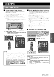
... IN terminal. 2. Roughly adjust the focus of the projection. up is completed, the temperature monitor (TEMP) lamp turns off automatically. If this happens, increase the temperature around the projector so that the image size fits in PROJECTOR SETUP menu. 3. After a short period, the indicator will illuminate and the projector will be displayed with the front leg adjusters. 5. Q Adjusting focus, zoom and shift Control buttons of the projector Pressing the LENS button changes the setup screen in red. Connect the supplied power cord (220 - 240...
... IN terminal. 2. Roughly adjust the focus of the projection. up is completed, the temperature monitor (TEMP) lamp turns off automatically. If this happens, increase the temperature around the projector so that the image size fits in PROJECTOR SETUP menu. 3. After a short period, the indicator will illuminate and the projector will be displayed with the front leg adjusters. 5. Q Adjusting focus, zoom and shift Control buttons of the projector Pressing the LENS button changes the setup screen in red. Connect the supplied power cord (220 - 240...
Operating Instructions
Page 20
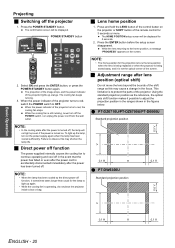
... power cord from the wall outlet. Failure to adjust the projection position in the ranges shown in the focus. Q PT-DZ6710U/PT-DZ6700U/PT-D6000U Standard projection position NOTE: • In the cooling state after lens position (optical shift) Do not move the lens beyond the bounds of the projector lights up the lamp, turn off . Projecting J Switching off , the lamp will be displayed. Press the POWER STANDBY button. The HOME POSITION setup screen will not light...
... power cord from the wall outlet. Failure to adjust the projection position in the ranges shown in the focus. Q PT-DZ6710U/PT-DZ6700U/PT-D6000U Standard projection position NOTE: • In the cooling state after lens position (optical shift) Do not move the lens beyond the bounds of the projector lights up the lamp, turn off . Projecting J Switching off , the lamp will be displayed. Press the POWER STANDBY button. The HOME POSITION setup screen will not light...
Operating Instructions
Page 25
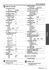
...-SCREEN DISPLAY OSD POSITION 1 2 3 4 5 6 7 8 9 OSD DESIGN 1 2 3 4 5 6 OSD MEMORY ON OFF INPUT GUIDE ON OFF WARNING MESSAGE ON OFF BACK COLOR BLACK LOGO1 BLUE LOGO2 STARTUP LOGO LOGO2 LOGO1 NONE FREEZE SIDE BY SIDE VIDEO RGB1 DVI-D OFF S-VIDEO RGB2 SDI PROJECTOR SETUP PROJECTOR ID ALL 1 - 64 Menu Navigation INSTALLATION FRONT/FLOOR FRONT/CEILING REAR/FLOOR REAR/CEILING HIGH ALTITUDE MODE OFF ON COOLING CONDITION FLOOR SETTING VERTICAL DOWN SETTING CEILING SETTING VERTICAL UP SETTING LAMP...
...-SCREEN DISPLAY OSD POSITION 1 2 3 4 5 6 7 8 9 OSD DESIGN 1 2 3 4 5 6 OSD MEMORY ON OFF INPUT GUIDE ON OFF WARNING MESSAGE ON OFF BACK COLOR BLACK LOGO1 BLUE LOGO2 STARTUP LOGO LOGO2 LOGO1 NONE FREEZE SIDE BY SIDE VIDEO RGB1 DVI-D OFF S-VIDEO RGB2 SDI PROJECTOR SETUP PROJECTOR ID ALL 1 - 64 Menu Navigation INSTALLATION FRONT/FLOOR FRONT/CEILING REAR/FLOOR REAR/CEILING HIGH ALTITUDE MODE OFF ON COOLING CONDITION FLOOR SETTING VERTICAL DOWN SETTING CEILING SETTING VERTICAL UP SETTING LAMP...
Operating Instructions
Page 28
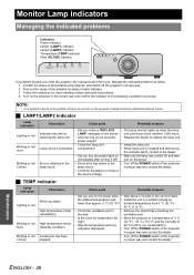
... the instruction for LAMP" message on the screen unit used hours have reached 1 800 hours. ambient temperature from 0 °C (32 °F) - 45 °C (113 °F). • Check the ventilation port is • Remove the object that is not installed. Monitor Lamp indicators Managing the indicated problems Indicators Power indicator Lamp1 (LAMP1) indicator Lamp2 (LAMP2) indicator Temperature (TEMP) indicator Filter (FILTER) indicator STANDBY(RED)/ ON(GREEN) LAMP TEMP FILTER STANDBY(RED)/ ON(GREEN) LAMP TEMP FILTER If a problem should occur with the projector, the indicators...
... the instruction for LAMP" message on the screen unit used hours have reached 1 800 hours. ambient temperature from 0 °C (32 °F) - 45 °C (113 °F). • Check the ventilation port is • Remove the object that is not installed. Monitor Lamp indicators Managing the indicated problems Indicators Power indicator Lamp1 (LAMP1) indicator Lamp2 (LAMP2) indicator Temperature (TEMP) indicator Filter (FILTER) indicator STANDBY(RED)/ ON(GREEN) LAMP TEMP FILTER STANDBY(RED)/ ON(GREEN) LAMP TEMP FILTER If a problem should occur with the projector, the indicators...

Operating Instructions
Page 29
... projector at high elevations 1 400 - 2 700 m (4 593 - 8 858 ft) sea level and HIGH ALTITUDE MODE in orange The ACF unit is OFF, it may be heard. • In a dusty environment, the guided remaining use time of the ACF unit is operating, operational sound may cause malfunction of STATUS in red. *2. 200 hours is not installed, displays "THE AIR FILTER HAS NOT BEEN INSTALLED PROPERLY." Monitor Lamp indicators J FILTER indicator The FILTER indicates the Auto Cleaning Filter (ACF) unit status...
... projector at high elevations 1 400 - 2 700 m (4 593 - 8 858 ft) sea level and HIGH ALTITUDE MODE in orange The ACF unit is OFF, it may be heard. • In a dusty environment, the guided remaining use time of the ACF unit is operating, operational sound may cause malfunction of STATUS in red. *2. 200 hours is not installed, displays "THE AIR FILTER HAS NOT BEEN INSTALLED PROPERLY." Monitor Lamp indicators J FILTER indicator The FILTER indicates the Auto Cleaning Filter (ACF) unit status...
Operating Instructions
Page 30
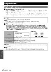
... replacing the Lamp unit Turn off after 10 minutes. Those figures are rough guidance and might be turned off. To clear the screen, press any button to prevent the risk of the projector in the PROJECTOR SETUP menu. Automatically the projector will stay until you keep using LAMP1/ LAMP2 of usage time using the lamp unit after 10 minutes. Wait for 10 minutes. NOTE: • The guide times...
... replacing the Lamp unit Turn off after 10 minutes. Those figures are rough guidance and might be turned off. To clear the screen, press any button to prevent the risk of the projector in the PROJECTOR SETUP menu. Automatically the projector will stay until you keep using LAMP1/ LAMP2 of usage time using the lamp unit after 10 minutes. Wait for 10 minutes. NOTE: • The guide times...
Operating Instructions
Page 31
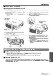
... 1 lamp unit cover fixing screw securely with a Phillips-head screwdriver. Handle Lamp unit screws Replacing the Auto Cleaning Filter (ACF) J Before replacing the ACF Wait until the cooling fan stops and turn freely, and remove the lamp unit cover. The FILTER indicator will inform you of STATUS in to attach securely. J Replacement procedure Q Removing and replacing the lamp unit 1. Press in the lamp unit until the screws turn off the POWER switch of the projector in correct direction. 5. Use a Phillips...
... 1 lamp unit cover fixing screw securely with a Phillips-head screwdriver. Handle Lamp unit screws Replacing the Auto Cleaning Filter (ACF) J Before replacing the ACF Wait until the cooling fan stops and turn freely, and remove the lamp unit cover. The FILTER indicator will inform you of STATUS in to attach securely. J Replacement procedure Q Removing and replacing the lamp unit 1. Press in the lamp unit until the screws turn off the POWER switch of the projector in correct direction. 5. Use a Phillips...
Operating Instructions
Page 32
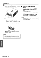
... FILTER 1. The confirmation screen will be turned on. • Do not switch the power on while the ACF cover removed. • The replacement timing of the ACF is in PROJECTOR SETUP menu. 2. Display the STATUS in correct direction and slightly push until the screws turn freely and remove the ACF cover. NOTE: • See FILTER COUNTER RESET and STATUS in PROJECTOR SETUP menu of the functional instructions that is 36 000 hours of usage. Turn on environment of use...
... FILTER 1. The confirmation screen will be turned on. • Do not switch the power on while the ACF cover removed. • The replacement timing of the ACF is in PROJECTOR SETUP menu. 2. Display the STATUS in correct direction and slightly push until the screws turn freely and remove the ACF cover. NOTE: • See FILTER COUNTER RESET and STATUS in PROJECTOR SETUP menu of the functional instructions that is 36 000 hours of usage. Turn on environment of use...
Operating Instructions
Page 33
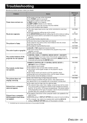
... distance from a laptop computer may not be correct. (You may be in the provided CD-ROM. The lens focus may not have a problem. The remote control ID setting is turned off. The color format may not have been set correctly. CD-ROM: See the functional instructions in use. Reference page*1 18 20 20 28 28 31 - The lamp unit cover has not been securely installed. The input source...
... distance from a laptop computer may not be correct. (You may be in the provided CD-ROM. The lens focus may not have a problem. The remote control ID setting is turned off. The color format may not have been set correctly. CD-ROM: See the functional instructions in use. Reference page*1 18 20 20 28 28 31 - The lamp unit cover has not been securely installed. The input source...
Operating Instructions
Page 36
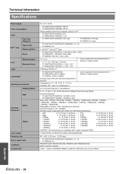
... follows in model number. Technical Information Specifications Power supply Power consumption Amps DLP™ chip Panel size (diagonal) Aspect ratio Display method Pixels Lens Motorized zoom Motorized focus Lamp Luminosity*2 Operating environment VIDEO/S-VIDEO RGB Scanning frequency*3 DVI-D YPBPR Color system Projection size Screen aspect ratio Installation Contrast ratio AC 120 V 60 Hz • PT-DZ6710U/PT-DZ6700U: 820 W • PT-DW6300U/PT-D6000U: 780 W During standby (when fan is stopped): Approx. 8 W*1 • PT-DZ6710U/PT-DZ6700U: 8 A • PT-DW6300U/PT-D6000U...
... follows in model number. Technical Information Specifications Power supply Power consumption Amps DLP™ chip Panel size (diagonal) Aspect ratio Display method Pixels Lens Motorized zoom Motorized focus Lamp Luminosity*2 Operating environment VIDEO/S-VIDEO RGB Scanning frequency*3 DVI-D YPBPR Color system Projection size Screen aspect ratio Installation Contrast ratio AC 120 V 60 Hz • PT-DZ6710U/PT-DZ6700U: 820 W • PT-DW6300U/PT-D6000U: 780 W During standby (when fan is stopped): Approx. 8 W*1 • PT-DZ6710U/PT-DZ6700U: 8 A • PT-DW6300U/PT-D6000U...

Operating Instructions
Page 39
...FILTER Compartment 13 Indicator 12 Indicator status 29 Replacing 31 FOCUS Adjusting 19 Remote control button 14 Focus ring 12 Front leg adjusters 12 FUNCTION Remote control button 14 Remote control function 23 I ID Remote control button 14 Setting 15 INPUT SELECT Control panel button 12 Remote control buttons 14 Remote control function 22 INSTALLATION Projection method 16 L LAMP Indicator status 28 Lamp unit compartment 12 LAMP1/LAMP2 indicators 12 Replacing 30 LAN Terminal 13 LENS Control panel button 12 Projection lens 12 Projector lens cover 11 Remote control button...
...FILTER Compartment 13 Indicator 12 Indicator status 29 Replacing 31 FOCUS Adjusting 19 Remote control button 14 Focus ring 12 Front leg adjusters 12 FUNCTION Remote control button 14 Remote control function 23 I ID Remote control button 14 Setting 15 INPUT SELECT Control panel button 12 Remote control buttons 14 Remote control function 22 INSTALLATION Projection method 16 L LAMP Indicator status 28 Lamp unit compartment 12 LAMP1/LAMP2 indicators 12 Replacing 30 LAN Terminal 13 LENS Control panel button 12 Projection lens 12 Projector lens cover 11 Remote control button...


